


This work aims to contribute to reducing environmental damage caused by the manufacturing of Portland cements (PC), through in-depth exploration into the durability of two mortars manufactured from blast furnace slag: an alkaline-activated one (AAS) and a hybrid cement (HS) with less than 20% clinker. The carbonation resistance of these eco-friendly mortars is compared to that of a mortar based on Portland IV cement. From a mineralogical point of view, DTA-TG and confocal Raman microscopy (CRM) tests have been carried out, along with measurement of pH changes, compression strength and total porosity. Böhme tests have been performed to evaluate changes due to carbonation in the wear behavior of the mortars under study. Using the CRM technique, it has been possible to establish a relationship between the carbonation of the systems with the unbound carbon content, as well as identify the different polymorphic phases of CaCO3 formed. The results obtained reveal that alternative AAS and HS mortars are more difficult to carbonate than Portland cement mortars, and that the effect of this process on the porosity depends on the nature of the hydroxides previously present in the pore solution. The carbonation of the surfaces also improves the abrasive wear resistance of the mortars under study.
Este trabajo pretende contribuir a la reducción de los daños medioambientales causados por la fabricación de cementos Portland (CP), mediante la profundización en la durabilidad de dos morteros fabricados a partir de escorias de alto horno: uno activado alcalinamente (AAS) y uno híbrido (HS) con menos del 20% de clínker. La resistencia a la carbonatación de estos morteros ecológicos se compara con la de un mortero a base de cemento Portland tipo IV. Desde el punto de vista mineralógico, se han realizado ensayos de DTA-TG y de microscopía confocal Raman (CRM), junto con la medición de los cambios de pH, la resistencia a la compresión y la porosidad total. Se han realizado ensayos Böhme para evaluar los cambios debidos a la carbonatación en el comportamiento a desgaste de los morteros estudiados. Mediante la técnica CRM se ha podido establecer una relación entre la carbonatación de los sistemas con el contenido de carbono no ligado, así como identificar las diferentes fases polimórficas de CaCO3 formadas. Los resultados obtenidos revelan que los morteros alternativos (AAS y HS) son más difíciles de carbonatar que el mortero de cemento Portland, y que el efecto de este proceso sobre la porosidad depende de la naturaleza de los hidróxidos previamente presentes en la solución de los poros. La carbonatación de las superficies también mejora la resistencia al desgaste abrasivo de los morteros estudiados.
Concrete is the most used building material in the world. It is estimated that by weight it is used five times more than steel, and in some countries this ratio can even be as high as ten to one [1]. Portland cement (PC) is the traditional binder for concrete. However, in the production of 1t of PC produced, around 1t of CO2 is emitted into the atmosphere. The World Cement Association (WCA) reports that cement industries emit 7% of the world's total CO2. The COP26 forum celebrated in November 2021 announced many sustainability plans, including the launching of the industrial deep decarbonization initiative (IDDI). Among other objectives, it seeks to create new markets for low carbon concrete to help decarbonize heavy industries because of cement industry CO2 emissions.
Nowadays, the search for new ways of improving construction materials is focused on total or partial substitution of some of the to enhance their properties and/or reduce their environmental impact and the material and economic resources needed to manufacture them [2]. For instance, incorporating demolition wastes could be a solution, although they present problems because of their low pozzolanic properties [3]. Another promising option is alkaline activation. It has been suggested that alkaline-activated materials (AAM)/geopolymers are the most suitable alternative for replacing PC [4]. AAM are made from waste materials rich in aluminosilicates, such as blast furnace slag, fly ash, metakaolin [5], or even bottom ashes from solid waste incineration [6]. Their mechanical strength and durability are directly attributed to N-A-S-H [7] and C-A-S-H [8] gels, different from the C-S-H gel obtained in PC systems. Another relevant difference between AAM and PC materials, besides AAM's lower Ca content, is their higher initial alkalinity, due to the activating solutions used during their manufacture.
AAM are currently implemented for infrastructure applications such as pavements, airports, residential or office buildings. However, the development of AAM at industrial level is still under study due to the use of liquid alkaline activators at very high concentration. These AAM have been mainly used in the manufacturing of prefabricated products, since the handling of alkaline solutions is better controlled. The handling of liquid alkaline activators requires a lot of care, and these activators generate a meaningful environmental impact [8], thought lower than that of PC [9]. The reported mechanical properties of properly formulated AAM are higher than those of PC [10,11] but they have shrinkage problems [12,13] that can affect their in-service life.
Recently, Palomo et al. [14] and Alahrache et al. [15] proposed new cementitious material formed combining PC and aluminosilicate materials, which are known as hybrid cements. Hybrid cements are composed of 20–30% of PC and around 70–80% of wastes (aluminosilicate materials), with the addition of an alkaline solid (approximately 3–5% of Na2SO4, for instance) [8]. Results on their early hydration kinetics and microstructure development have been published [16]. Hybrid cement microstructure comprises mixtures of cementitious gels, such as C-S-H and C-A-S-H for blast furnace slag [17] and the mix of amorphous gels such as C-S-H and N-A-S-H for fly ash [18]. Depending on their formulation, they can achieve good mechanical strengths [10], which comply with the requirements of the EN 196-1 standard. The addition of sodium sulfate as activator increases the percentage of phases such as ettringite and gypsum in the binder. However, the low percentage of Na2SO4 used for the formulation of hybrid cements would cause that the amounts of these phases formed cannot be considered harmful for the mechanical properties of the material [19]. Today hybrid cements are materials that are still being developed [20], and published calculations estimate that their use instead of PC could provide a good balance between carbon footprint and water footprint reductions [9], as a thermal storage system in concentrated solar power technology [21]. However, the smaller shrinkage problems and greater easiness of their in-construction use in comparison with AAM (due to the resort to a solid activator that can be added to the powder mix) allow to foresee a higher implementation as substitute for traditional PC.
During the natural exposure of PC concrete structures in the atmosphere, the CO2 diffuses into the concrete and carbonation takes place, originating CaCO3 precipitation through a series of reactions that have been detailed in previous literature, with pH decreasing in the pore solution [22]. The reaction of the CO2 dissolved in the aqueous phase of the pores with the portlandite of the PC binder leads to the formation of carbonate and bicarbonate ions. The CaCO3 formed during carbonation of Ca-rich binders exhibits high hardness and good volumetric stability and chemical inertia [23,24]. CaCO3 can precipitate with different morphologies (vaterite, calcite, aragonite), depending on the carbonation conditions (temperature, humidity, etc.) and on the chemical composition of the pore solution [25]. Its precipitation in the pores reduces the number of low-size pores [26] and decreases the permeability and the penetration of aggressive species [27]. At the same time, during carbonation, CO2 can also react with the C-S-H gel formed during the hydration of the PC. In this case, the gel is decalcified and CaCO3 is also formed. This chemical transformation affects the durability of concrete structures.
The effect of carbonation on the mechanical properties of PC materials has been reported as being both positive and negative, depending on the chemical composition of the cementitious material and on the carbonation conditions [28]. However, a noticeable consumption of C-S-H gel after a very intense carbonation process compromises the ductility and strain capacity of the structure [29]. Nevertheless, no information regarding the effect of carbonation on the wear performance has been found in the literature up to now, in spite of the fact that it is a key property for common concrete applications such as pavements.
On the other hand, carbonation usually implies a certain amount of shrinkage [30], which can negatively affect the in-service performance of the materials. Some authors blame the portlandite dissolution for this shrinkage behavior [31], while others assert that the decalcification of C-S-H and its transformation into a silica gel with lower volume is responsible for the shrinkage [32]. The shrinkage can increase the number of coarse pores [33] and even favor crack generation [34]. This risk of cracking is higher in materials with a high CaO/SiO2 ratio [35].
From the point of view of durability, the carbonation of materials is one of the most important problems in reinforced structures. The passivity of the carbon steel reinforcements embedded in concrete is guaranteed by the alkalinity of the solution contained in the pores of the concrete. When carbonation occurs in mortars, the pH decreases, thereby increasing the vulnerability of embedded reinforcing rebars to corrosion [36]. The carbonate-bicarbonate buffer that tends to appear in the pores sets the pH in values of about 9.6, where the carbon steel acts as an active system, corroding in a general way [37]. Moreover, the decrease in Ca(OH)2 content in the pore solution lowers the Cl− concentration that the embedded metal is able to withstand before pitting [38,39].
There are several factors influencing mortar carbonation: the time that mortars are exposed to CO2 partial pressure, humidity, mortar porosity, previous cracks, etc. Obviously, the composition of the cementitious binder is also a key point for determining the effect and the rate of the carbonation process. Up to now, most of the carbonation studies have been carried out on PC-based materials. Moreover, fly ash presence in the binder (as a supplementary material) has been proven to increase the carbonation rate for equal water/cement ratios [40]. At the same time, fly ash-based AAM have also been demonstrated to be susceptible to carbonation in the atmosphere [41], and authors such as Khan et al. [42] have reported a higher susceptibility of this type of alternative materials to CO2 exposure than PC materials. Thus, it has sometimes been assumed that AAM carbonate more easily than PC [43], due to the absence of precipitated portlandite in their microstructure.
However, the mechanism of carbonation of AAM is strongly dependent on their formulation, the finesses of the components and the curing conditions [44]. Effects of carbonation on the microstructure of pastes manufactured with metakaolin and slag occurs, and decalcification of C-(N)-A-S-H gels and formation of N-A-S-H gels have been reported. It has been published that carbonation of AAM does not meaningfully affect their compression strength [45], although losses of compressive strength have been detected for some AAM made from slag (AAS), depending on their formulation and slag amount [46].
On the other hand, different techniques have been used to follow the formation of carbonates in cementitious systems, such as XRD, DTA-TG or FTIR, among others. However, these conventional characterization techniques have certain limitations when it comes to detecting less crystalline phases, such as aragonite or vaterite, while this information can be obtained through the use of confocal Raman microscopy (CRM) technique.
Raman spectroscopy, when combined with CRM, is a non-destructive technique that allows the phase composition to be identified in inorganic [47] and carbon-based materials [48] with high spatial resolution [49]. Torres-Carrasco et al. [50] used the CRM technique for the in situ study of conventional PC hydration at different curing ages, and was able to observe the formation of new phases and even the disappearance of water. In addition, through the use of this technique, it has been possible to obtain information on the weathering processes suffered in a conventional cement, when the appearance of CaCO3 occurs [49]. The presence of this carbonate is not only found in the form of calcite, but also in the different polymorphic phases, such as aragonite or vaterite. In addition, that fact of being a technique that incorporates microscopy is important, as it allows the different phases that are present to be quantified. Similarly, there are studies where CRM has been used for alkali-activated systems [51].
In conclusion, it is of interest to examine the effect that carbonation can have on the in-service performance of AAS and provide new information on hybrid slag (HS) materials after CO2 exposure when compared to PC mortars. The formulation chosen for the AAS and HS is based on the optimization analyses [52] and the good previous results obtained for these formulations [53]. The obtained information is key for making implantation of alternative eco-friendly binders possible in applications exposed to the atmosphere, where carbonation can take place, especially if they are standing wear loads.
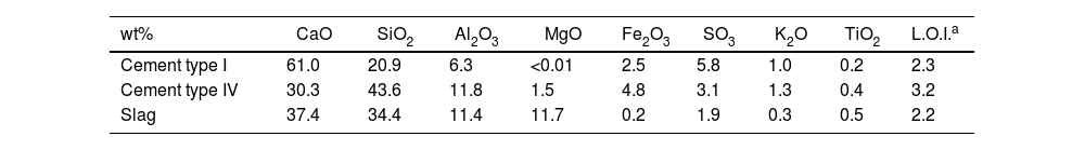
Materials and methodsMaterialsTwo commercial PC (cement type I and cement type IV) provided by Cementos Portland Valderrivas (Madrid, Spain) and a blast furnace slag provided by the Aviles factory (Asturias, Spain) were used. Table 1 shows their chemical composition determined by X-ray fluorescence (XRF). In all the materials, the main oxides present are CaO, SiO2 and Al2O3. However, there are clear differences in the amount of CaO, with cement type I having the highest content. Cement type IV and the slag have quite similar amounts for all oxides present, except for MgO. In this case, slag exhibits a higher content than cement type IV.
Chemical composition of raw materials (% by wt.) determined by XRF.
| wt% | CaO | SiO2 | Al2O3 | MgO | Fe2O3 | SO3 | K2O | TiO2 | L.O.I.a |
|---|---|---|---|---|---|---|---|---|---|
| Cement type I | 61.0 | 20.9 | 6.3 | <0.01 | 2.5 | 5.8 | 1.0 | 0.2 | 2.3 |
| Cement type IV | 30.3 | 43.6 | 11.8 | 1.5 | 4.8 | 3.1 | 1.3 | 0.4 | 3.2 |
| Slag | 37.4 | 34.4 | 11.4 | 11.7 | 0.2 | 1.9 | 0.3 | 0.5 | 2.2 |
From the raw materials described, three different mortars, with different binders, were manufactured:
- •
A conventional mortar made with 100% cement type IV PC (labelled as CEM IV), as a binder. This mortar is used as a reference to compare the performance of new slag-based mortars with a commercial one under same carbonation conditions. Water was used as liquid in the preparation of this mortar.
- •
AAS mortar manufactured with 100% of blast furnace slag as the binder. A commercial solution of sodium silicate (or waterglass) was used as the alkaline activator, with a SiO2/Na2O ratio of 1.2.
- •
HS mortars made from a mix of cement type I (17.5wt%) and blast furnace slag (77.5wt%). Furthermore, a percentage of Na2SO4 (5wt%) was added as the activator to favor the hydration process of the mortars and water was used as solution.
A 3/1 sand/cementitious material ratio was always used. The liquid to solid ratio in the mortars was 0.5 for CEM IV and AAS, and 0.42 for HS. The ratio was selected in equal consistency according to the UNE-EN 1015-3 standard.
Fifteen mortar prismatic specimens of 4cm×4cm×16cm per composition were manufactured. Immediately after molding, the specimens were covered with a film to avoid surface carbonation due to the presence of CO2 in the environment, according to the European standard UNE-EN 12390-12. The mortars were demolded 24h after molding and subsequently all mortars were kept in a curing chamber at 94–95% relative humidity and 20±2°C for 28 days.
After curing for 28 days, the specimens were placed in the carbonation chamber. To ensure that the carbonation front was on the entire surface, non-coated samples were used, thus facilitating the penetration of CO2 in all directions. The carbonation test consisted of a closed cabinet, where the conditions were 24°C, 75% relative humidity and air with 3% (v/v) CO2. These conditions were in accordance with the UNE-EN 12390-12 standard. The chamber conditions were periodically monitored. The mortar specimens were removed after 7, 14, 28, and 56 days of exposure (labelled as “7–C”, “14–C”, “28–C” and “56–C”, respectively). These specimens were compared to 28-days cured mortars, labelled as “0”.
Tests conductedAfter each exposure time, the samples were extracted from the chamber and the specimens were subjected to flexural loads to evaluate the cross-section of the specimens according to the UNE-EN 196 standard. Each material and condition were tested in triplicate. Phenolphthalein was used to measure the carbonation front on the cross-section of the prismatic samples according to the European standard UNE-EN 12390-12. In addition, the average pH change was measured with a pHmeter of ExStick Waterproof electrode, whose active tip has 0.8-mm diameter. It was placed on the cross-sectional surface obtained from the samples with a precision cutting machine. pH values were measured in three different points of the surface, always at 0.6±0.4cm depth, and three different specimens of each system were measured to obtain reliable values.
The study of the porosity of the cured mortars and the effect of carbonation was characterized by different complementary techniques. Porosity was determined by the Archimedes technique following the UNE-EN 993-1 standard, using three specimens per material, comparing it to the density measured by the gas displacement method with a helium pycnometer ACCUPYC 1330. The specimens under study were 1cm×1cm×1cm cubes obtained from the mortar surface.
Pore surface area was calculated by the Brunauer, Emmett and Teller (BET) technique with Gemini VII 2390 V1.03t Micrometrics equipment. After degassing at 90°C for 2h in order to remove water and organic vapor, approximately 0.5g of powder from each mortar was measured. Simultaneous differential thermal analysis (DTA) and thermogravimetry (TG, SETSYS Evolution, SETARAM Instrumentation, France) was employed to analyze the surface of all carbonated and as-cured samples at a heating rate of 10°C/min to 1100°C. For both characterization techniques, to measure the surface area and the DTA in the carbonated samples, the powder was obtained by pulverizing from CO2 exposed area of the sample surface.
The distribution of phases at the surface was performed by CRM on WiTec alpha300 R equipment (Ulm, Germany). Raman spectra were recorded over a spectral range from 100 to 3700cm−1. Confocal Raman measurements were accomplished using a 532nm excitation laser (green laser) and a 50× objective lens (N.A. 0.80) with an area of focus over the samples at 5mW laser power. The scan area was 50μm×50μm, the parameter of the Raman image was 50×50 pixels, and integration time per pixel was 1.0s. Collected Raman spectra were analyzed using the WiTec results module, and using “cosmic ray removal” (CRR) and “background subtraction” (BSub) of data for their correction.
Mechanical properties (compression strength) were measured according to the EN 196-1 standard. Three specimens corresponding to each mortar and exposure condition under study were tested.
The analysis of the mechanical performance of the mortars was completed with a wear test. The Böhme machine (Ibertest, Madrid, Spain) was used to perform the abrasive test on the mortars in accordance with the UNE-EN 13892-3 standard. The tests were performed at room temperature. Brown fused alumina (Al2O3) was used as an abrasive material, and the applied load was 294N. Three samples of 4cm×4cm×8cm of each mortar were tested. As the standard suggests, mass loss was measured in each sample, and volume loss was determined according to Eq. (1):
where ΔV is the total volume lost in cm3 after 16 cycles, Δm is the mass lost after 16 cycles and ρ is the mortar density.Results and discussionDifferential thermal analysis (DTA) and thermogravimetry (TG)
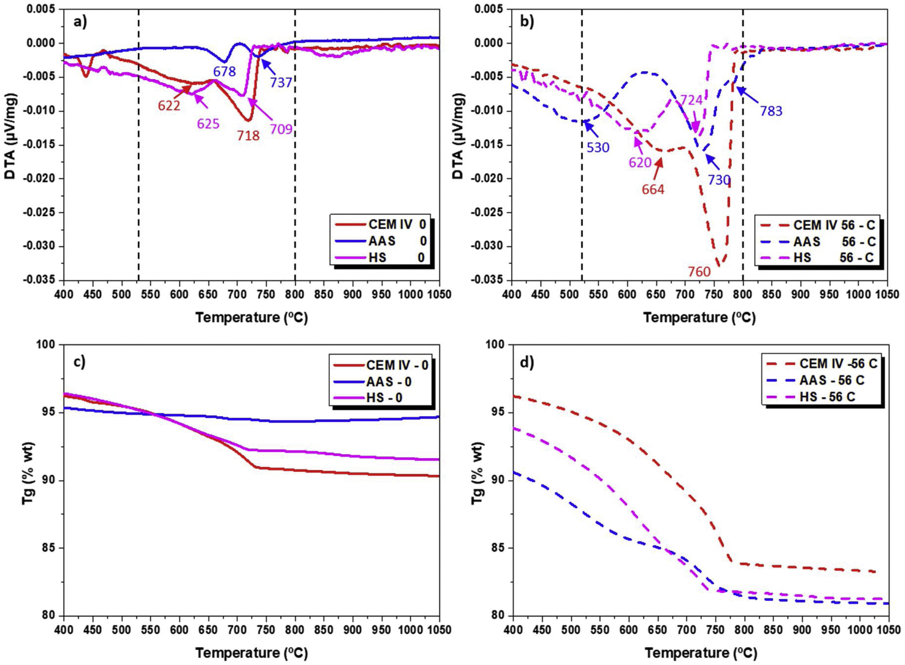
To obtain information about the chemical changes that took place in the surface of the different mortars due to exposure to CO2-rich air, DTA measurements were carried out. Fig. 1a and b shows the DTA for each system evaluated before and after undergoing the complete carbonation test. If a temperature range between 530 and 800°C (where decomposition of carbonates formed during carbonation takes place) is considered, clear differences are observed among the systems. There may be different calcium, sodium, potassium and magnesium carbonates from the reaction of the CO2 with the hydroxides present in the pore solution in the different mortars. Moreover, it is well known that different CaCO3 polymorphs (vaterite, aragonite, calcite) can be formed by carbonation of PC systems such as CEM IV [49,54].
 after curing (0 days) and (b) after carbonation (56-C). TG of mortars (c) after curing and (d) 56-days carbonation.")
In CEM IV mortar, peaks that can be identified with carbonate decomposition appear before carbonation (Fig. 1a) at 622°C and 718°C. These peaks indicate that a slight carbonation has already taken place during poor storage of the raw materials. The transformation occurring at low temperature is identified with the decarbonation of low crystalline calcium carbonates while the other corresponds to calcite with higher crystallinity. Due to the small potassium content in the cement (Table 1), a very small presence of this metal in the carbonates cannot be completely discarded. After carbonation, the intensity of both peaks increases and they appear shifted to higher temperatures (664 and 760°C, Fig. 1b). This fact confirms that the exposure in the chamber not only has clearly increased the amount of carbonates formed but also that the stability and crystallinity of the calcium carbonates formed are higher.
For the HS mortar (Fig. 1a and b), two peaks can also be observed before carbonation at temperatures quite similar to those where transformations have been detected for CEM IV. That is to say, the presence of similar carbonates can be assumed, but the presence of high crystalline carbonates can be considered proportionally lower in HS-0 than in CEM IV-0. After the exposure in the chamber, both peaks increase their intensity in HS due to the 3% CO2 exposure, confirming the formation of new carbonates in the surface. However, their shift to high temperatures and signal increase are lower than those observed for CEM IV mortar. For HS mortars, activated with Na2SO4, the interference of sodium in the carbonation process must be initially considered.
The DTA corresponding to AAS-0 mortar (Fig. 1a) only shows two very small peaks that appear at temperatures that are higher than in the other two materials under study. This suggests that more stable carbonates are present. Bearing in mind the different chemical composition of the pore solution of AAS, probably rich in sodium hydroxides (from the activator) and with a significant presence of Mg(OH)2 (from the slag, as can be seen in Table 1), carbonates with Na and/or Mg are expected. The different chemical composition of the carbonates can also explain the different temperatures detected.
After carbonation, three different transformations can be observed for AAS - 56C, one at lower temperature, about 530°C, and two at 730 and 783°C. These results reveal that different carbonated products are being formed in AAS than they are in the HS or CEM IV-mortar. The low temperature transformation is often identified with the degradation of calcium carbonates coming from gel decalcification [55].
On the other hand, Fig. 1 also shows the TG for all mortars before (0, Fig. 1c) and after the carbonation process (56-C, Fig. 1d), as examples of all the TG analyses carried out. From this study, the mass loss between 530 and 1000°C, which is the weight loss in the temperature range of the decomposition of carbonates (Ldc), was used to calculate the amount of carbonates [49]. The equation used for calculating weight loss is [56]:
where m is the weight of the sample at different temperatures (530 or 1000°C). Fig. 1c and d mainly shows the weight loss of the Ldc. The weight loss ends at approximately 800°C, being compatible with carbonates formed during carbonation, as no other carbonates (aggregates) were added to the mortar [55]. Comparing the 0 and 56-C curves of Fig. 1c and d, the range of loss for carbonates is higher in the exposed samples than in 0 samples.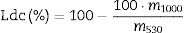
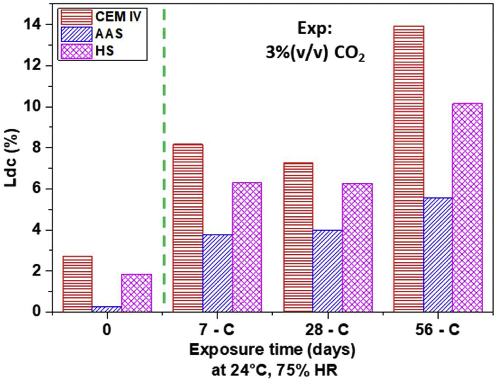
Fig. 2 shows the results of weight loss in the Ldc zone for the different mortar surfaces. It can be seen that the CEM IV mortar has the greatest increase (approximately 70%) in the contribution corresponding to the presence of carbonates, compared to the CEM IV-0 sample. The CEM IV surface has the highest percentage of carbonates present from the beginning of the test up to 56 days of exposure in the chamber. The AAS system presents a lower percentage of carbonates at the beginning (as DTA signals show, Fig. 1a), and, as it carbonates due to the presence of CO2 and humidity, more carbonates appear, reaching a content of 5.57% in the AAS-56 surface. As for HS, its behavior in the Ldc region reveals an intermediate performance between that of the CEM IV and the AAS system.
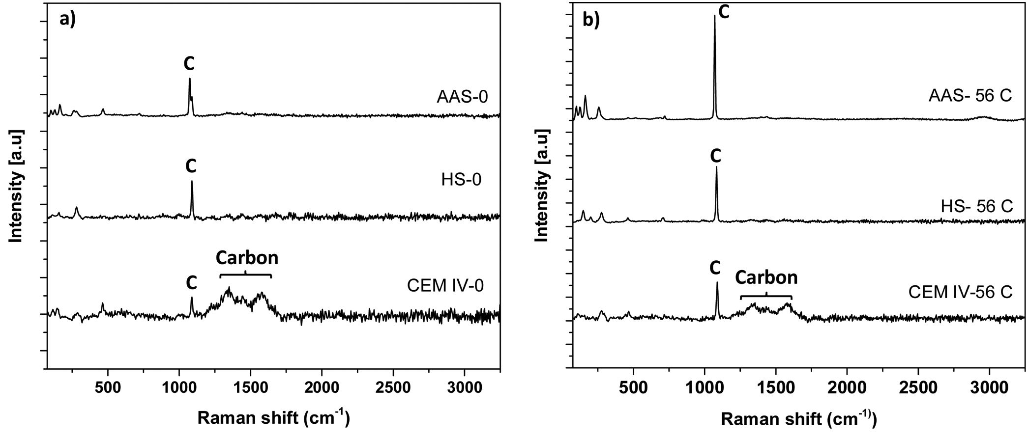
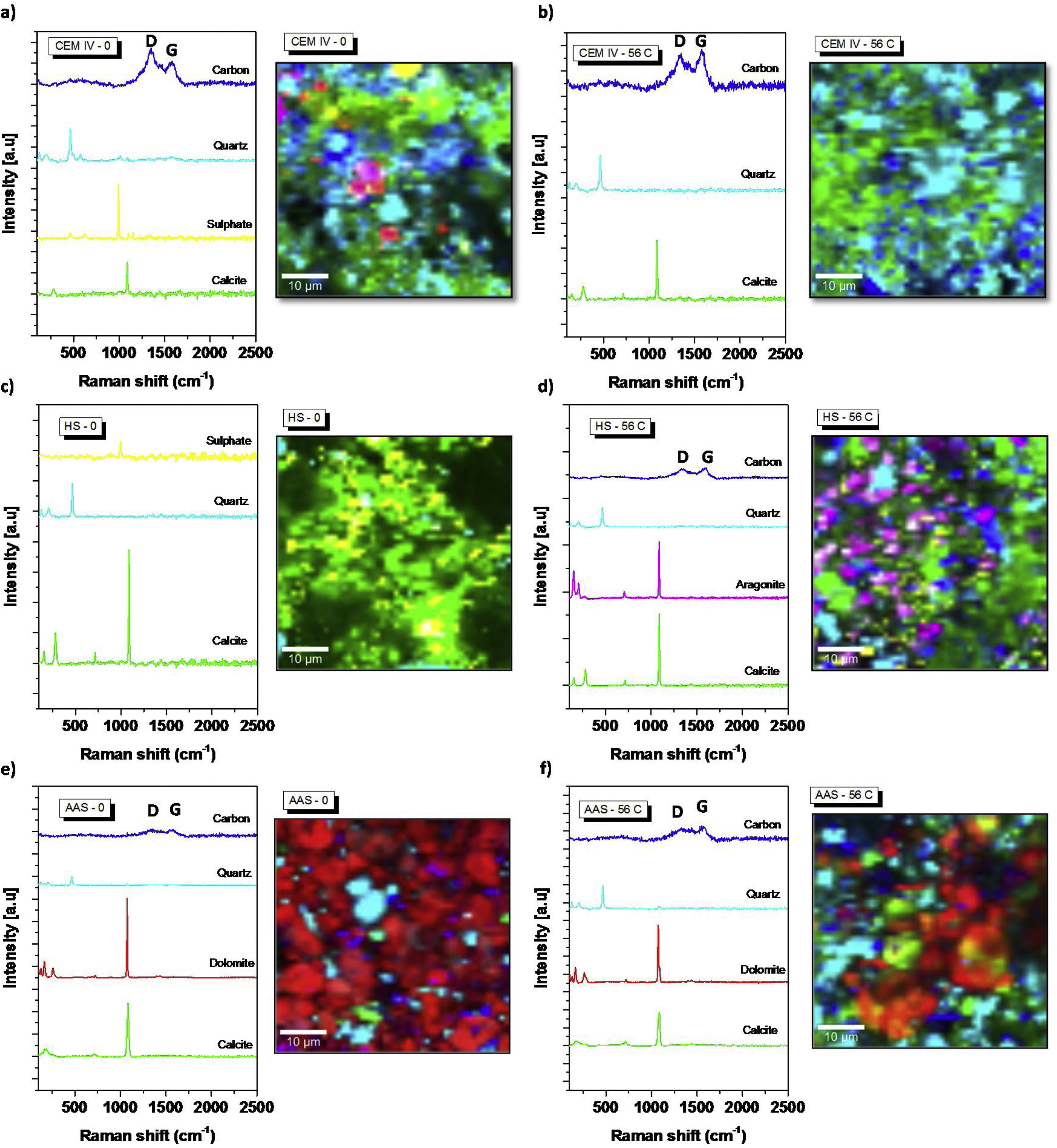
Characterization by confocal Raman microscopy (CRM) for all mortars.")
Using CRM, the average spectra of the surface of the systems evaluated can be observed in Fig. 3. The different phases present at room temperature in the surface after curing of the cement can be identified, that is to say, the chemical nature of precipitated carbonates that affect the porosity of the materials can be identified with reliability, for instance. However, this test is not sensitive enough to identify the compounds present in the pore solution and its changes due to CO2 exposure.
 0 days (after curing, without carbonation) and (b) after 56 days of carbonation.")
For CEM IV-0 mortar, the main Raman band is observed at ca. 1100cm−1, corresponding to the presence of CaCO3 in the form of calcite [57,58]. The presence of calcite in the CEM IV-0 mortar is indicative of a slight carbonation of the system, which may be due to the presence of CaCO3 from the beginning, in the raw cement itself, mainly due to a material weathering phenomenon (poor storage) [49]. These results are coherent with the carbonation of the surface of the as-cured samples already observed by DTA (Fig. 1). Nevertheless, it is important to note that the CRM technique is much more sensitive to the surface identification of any type of carbonate, whether it is more or less crystalline.
Fig. 4a shows the average spectra of each phase identified in the CEM IV-0 sample. In addition, the Raman micrograph of the sample is shown with the presence and distribution of each of the phases. It can be clearly seen that calcite is present from the start. The presence of quartz due to the aggregate used is evident throughout the sample. Finally, the presence of sulfate is observed, with a Raman band at ca. 1002cm−1[50], indicative of the presence of sulfur from the pozzolanic additions to cement type IV (see Table 1) that has formed sodium sulfate compounds.
 CEM IV-0; (b) CEM IV-56C; (c) HS-0; (d) HS-56C; (e) AAS-0; (f) AAS-56C.")
Detailed spectral regions of average Raman spectra corresponding to the Raman bands associated to the presence of the main phases in each system. Raman images by CRM of the distribution of main phases present in each system: (a) CEM IV-0; (b) CEM IV-56C; (c) HS-0; (d) HS-56C; (e) AAS-0; (f) AAS-56C.
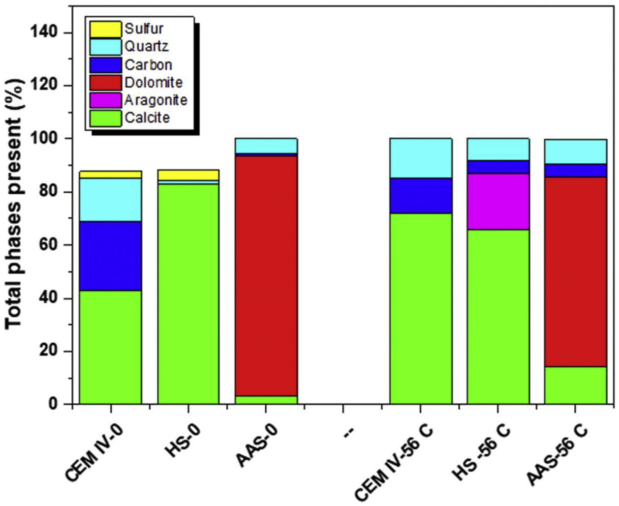
When CEM IV-0 mortar is subjected to the accelerated carbonation test, clear differences in its mineralogical composition are observed, as shown in Fig. 4a and b. The presence of the Raman bands at ca. 1100cm−1 becomes more intense and clearly increases the proportion of calcite in the region (light green) and small presence of dolomite (Ca,Mg(CO3)2). From a quantitative point of view, Fig. 5 shows the presence of carbonates before and after the test. It can be clearly seen how there is an increase of approximately 50% in calcite, which is the system that has carbonated the most, as TG results in the Ldc region shown (Fig. 2).

Regarding the average spectrum of the HS-0 system (see Fig. 3), a different behavior is observed compared to the CEM IV-0. There is a Raman band at ca. 1100cm−1 (CaCO3, calcite) and, in addition, another Raman band at ca. 1002cm−1 corresponding to the presence of sodium sulfate. In this case, (see Fig. 4c), the presence of sodium sulfate is due to the use of Na2SO4 as a solid activator in the preparation of the hybrid system (at 5% by weight). When the carbonation of the mortar occurs (HS-56C, see Figs. 3b and 4d), the presence of calcite becomes more evident, both in the intensification of the Raman band and in the distribution throughout the tested region. In addition, by using CRM, the existence of a more amorphous phase of calcium carbonate can be corroborated, specifically the presence of aragonite, whose Raman band appears at ca. 1084cm−1, which corresponds to the ν1 (CO32−) symmetric stretching mode [59]. However, aragonite and calcite cannot be differentiated using this Raman band, but there are other Raman peaks (ν4 modes) in aragonite that are present such as the Raman band at ca. 700cm−1 (corresponding to the doubly degenerate in-plane vibration, ν4). There is also the presence of other weak Raman bands located at ca. 200 and 153cm−1, in line with previous studies [49,60,61]. In terms of quantification (Fig. 5), there is a slight increase in the percentage of CaCO3, but what can be primarily seen is that aragonite can be formed during CO2 exposure in this hybrid material under tested conditions. The fact that Na2SO4 was detected in HS-0 is also in agreement with the interference of Na cation in the carbonation process, as shown in Fig. 1b. Although it has not been detected in HS-56C, it is important to take into account the size of the measured surface.
The AAS-0 system shows an average spectrum (see Fig. 4e) similar to the HS-0 mortar, where the presence of calcite is shown at ca. 1100cm−1. Moreover, sulfates are present, with a Raman band at ca. 1002cm−1 from the blast furnace slag itself. From the beginning, the presence of dolomite (CaMg(CO3)2), another carbonate, is observed. The Raman bands originating from ν1 (at ca. 1080cm−1), ν3 (at ca. 1441cm−1) and ν4 (at ca. 722cm−1) modes are in close agreement with the suggested interpretation by Edwards et al. [62] and Krishnamurthy [63]. The presence of dolomite from the beginning may be due to the presence of a high percentage of magnesium in the initial composition of the blast furnace slag (see Table 1). This in agreement with DTA results (Fig. 1) suggesting carbonates with different cations in their composition. However, when this sample is exposed to carbonation (AAS-56), it is observed that the presence of calcite becomes more evident.
Fig. 5 shows the quantification of phases detected by CRM, being the amount up to reach 100% – for the as-cured mortars – corresponding essentially to detection of pores. It can be concluded that the system that has suffered the most intense formation of calcium carbonate during carbonation is CEM IV. The precipitated carbonates in the mortars are always CaCO3 in CEM IV and HS, while in AAS the Mg content makes the dolomite predominant. Moreover, CaCO3 is always found as calcite, except in HS after 3% CO2 exposure, where the chemistry of HS in these conditions causes the formation of aragonite in the surface.
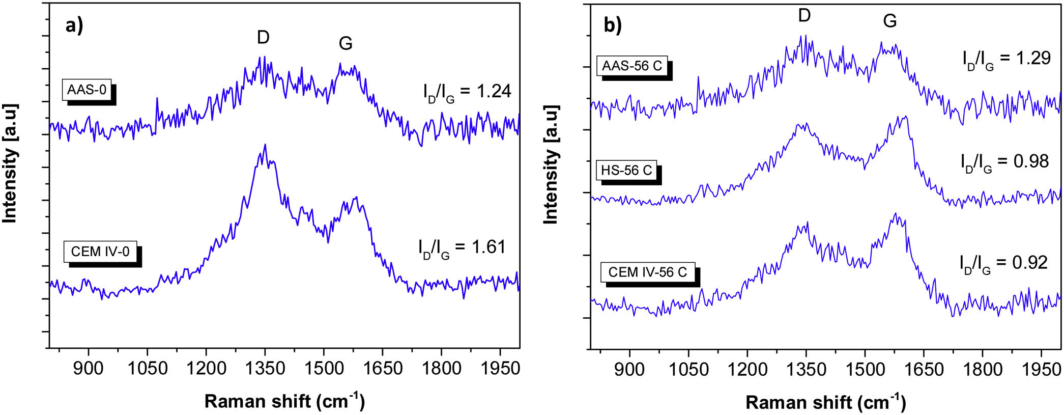
In Fig. 6, there is a detailed plot of characteristic Raman bands related to the presence of carbon in the sample, contributions already seen in Fig. 3. One band is observed at ca. 1365cm−1 (D peak), and corresponds to the disordered carbon structure. The other band (G peak) appears at ca. 1615cm−1, and is attributed to the presence of graphitic carbon (ordered state) (see Figs. 3 and 4) [48,64]. The carbon presence is clearly related to components of cement different from the pure clinker. Carbon is evident in CEM IV-0 mortar (both before and after the carbonation process), while in the average spectra of HS-0 and AAS-0 systems, it is not so significant. In Fig. 4, this phase is present in all systems except HS-0.
 before carbonation (after curing) and (b) after carbonation conditions.")
In CEM IV-0, the intensity of Raman D band (ID) is higher than that of Raman G band (IG), with ID/IG ratio being 1.61. When ID/IG ratio >1, it means that there is a greater structural disorder of the carbon, which is also more amorphous [48]. The same thing occurs in the AAS-0 system, where the ID/IG ratio=1.24. However, when the carbonation of the mortars occurs, a change in the intensities of the D and G bands is observed in the CEM IV-56C system, showing an ID/IG ratio=0.92. When this intensity ratio is less than 1, it is because the carbon present has predominantly a high degree of graphitic phase. This also occurs in the HS-56C mortar. This indicates that Portland cement (the presence of clinker) in the CEM IV and HS mortars induces greater carbonation, since the initial character of the carbon present in the systems is predominantly amorphous (more reactive). This carbon is more susceptible to forming carbonates with the presence of calcium, CO2 and relative humidity in the medium, as TG has shown (Fig. 2). The fact that AAS, with ID/IG ratios >1, do not carbonate as much as other studied mortars, and that this ratio does not seem to decrease with the carbonation process, could be related to the specific nature of AAS. These materials usually show very low porosities [10,52], and a pore solution very rich in Na [65] can strongly hinder the carbonation process. From the beginning, different polymorphs of CaCO3 appear (calcite and dolomite type) and, subsequently, they can still be found.
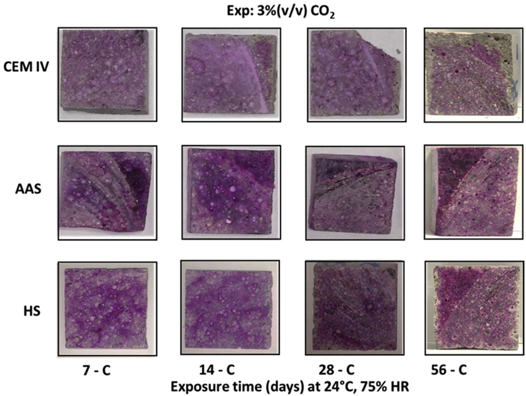
pH measurement and carbonation depthCarbonation maximum intensity occurs in the mortar surface and decreases as it goes into the mortars. The development of this carbonation initially occurs due to the reaction with the hydroxides present in the pore solution, so carbonation inward progress can be monitored by pH changes.
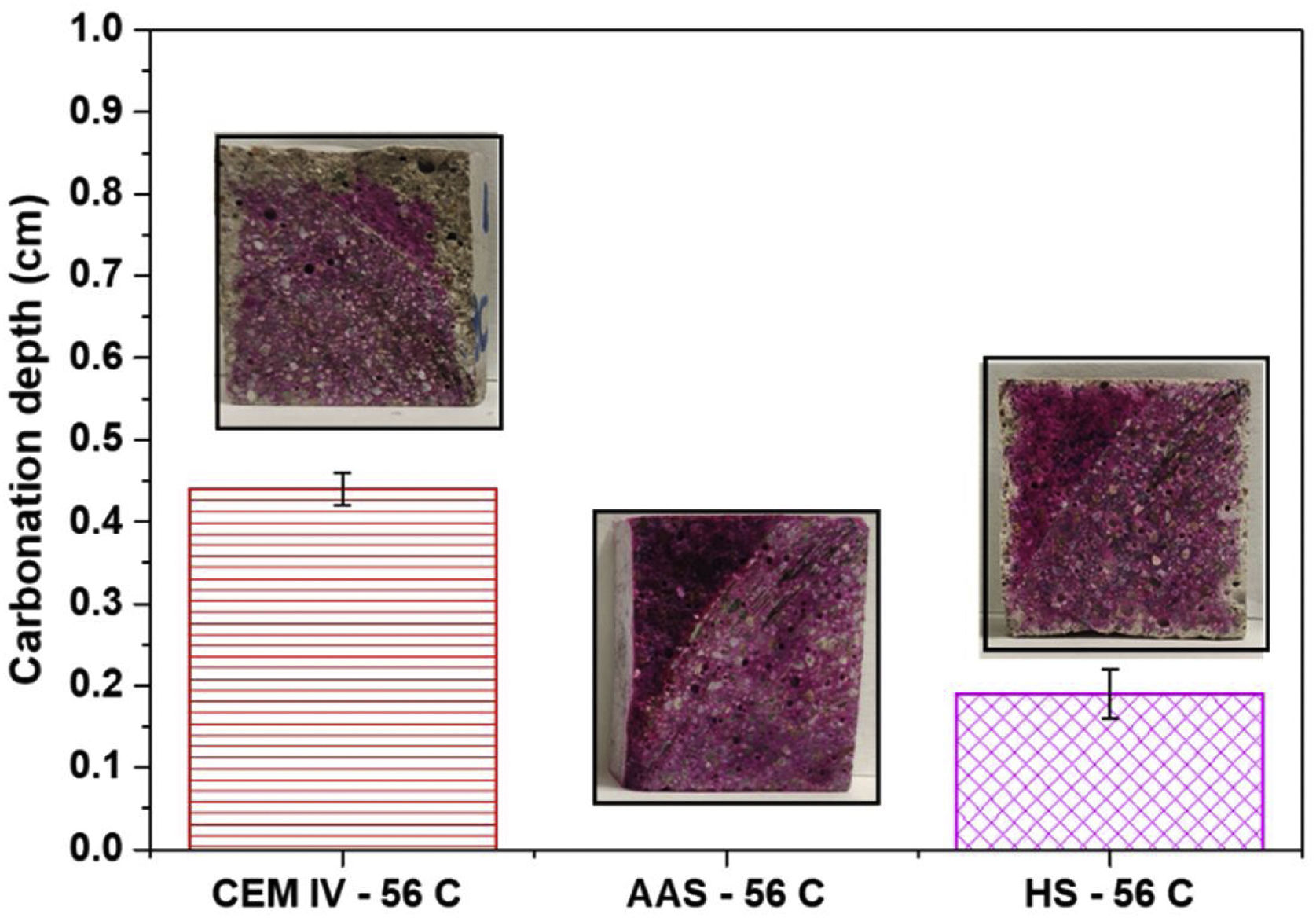
The reaction with the OH− ions causes a decrease in the pH that can be monitored in different ways. Fig. 7 shows the cross-section of the mortars sprayed with phenolphthalein after different CO2 time exposures. After 7 days of exposure, all mortars’ cross-sections are completely magenta colored, meaning a pH higher than 10 for the mortars. The observations in eco-efficient mortars after 14 and 28 days indicate that these materials maintain their alkalinity at values higher than 10 through all the cross-sections. However, after 14 days the region closest to the surface of CEM IV mortars is colorless, indicating a significant decrease in pH. After 56 days in the carbonation chamber, it can be noted that AAS mortar keeps the magenta color throughout its section, while the colorless region starts to appear in the surface of HS mortar and, for the CEM IV, the colorless region continuous its growth from the surface to the bulk of the samples.

Fig. 8 shows the carbonation depth after 56 days of CO2 exposure in the carbonation chamber. CEM IV mortars present an average thickness with a low pH of about 4.5mm (phenolphthalein is assumed to be colorless under 8.2, with its turning range between 8.2 and 10.0). The average thickness of the colorless section has been determined as an averaged value from measurements at different points of the transverse sections. The penetration of the de-colored carbonation front determined with phenolphthalein for HS is barely half of the determined CEM IV after the 56 days of exposure in the carbonation chamber.

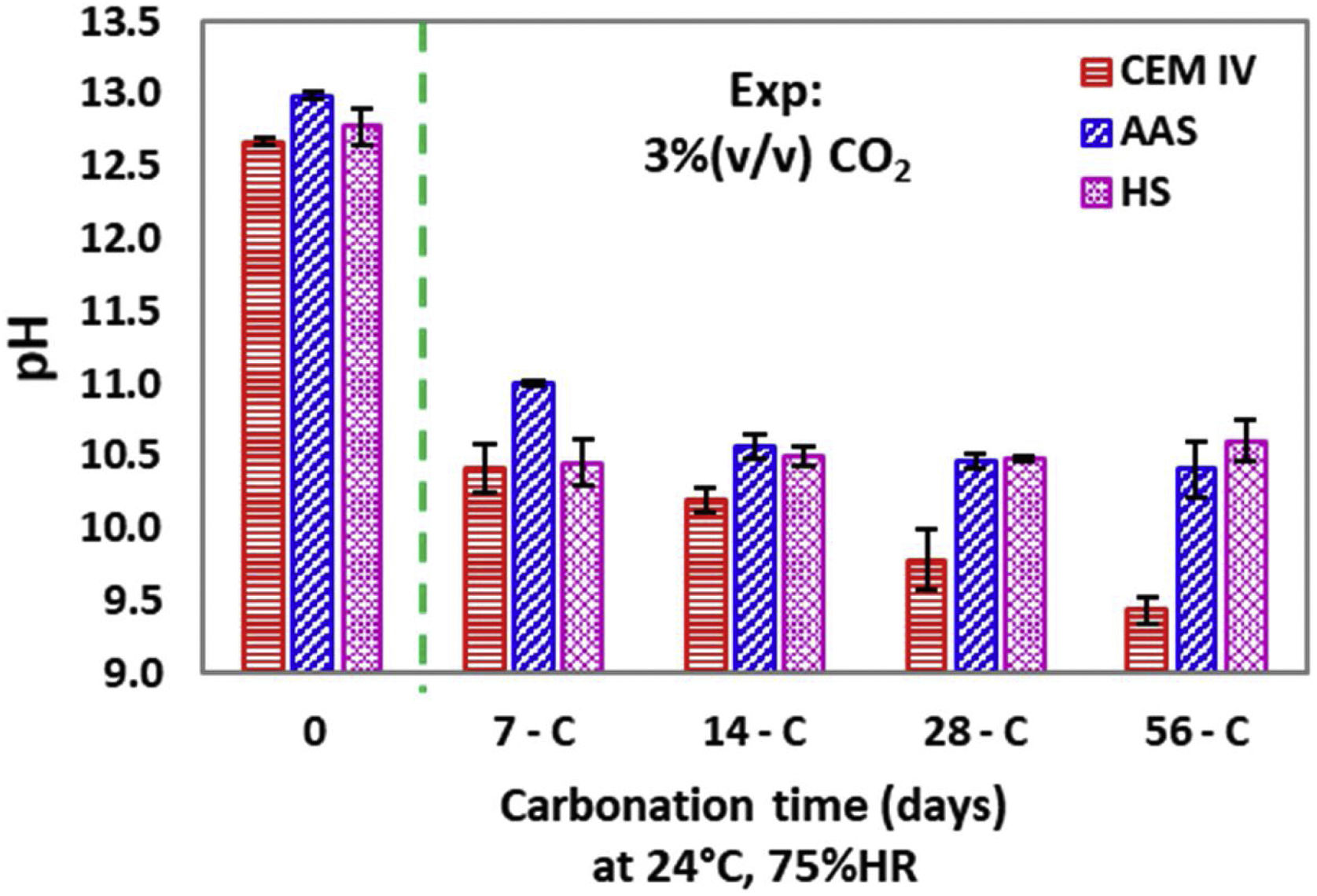
The pH of the samples was also quantified with an electrode in the cross-sections, in points close to the original surface (Fig. 9). With the electrode, information about moderate pH decreases (enough to keep the phenolphthalein purple) is obtained and the carbonation process can be monitored with more detail.

For CEM IV, considered as reference in the present study, a marked pH decrease takes place from the very beginning of the exposure in the carbonation chamber, and then the pH slowly decreases as the exposure is extended. The thick tip of the pH electrode used (0.8-cm diameter) only obtains results with very coarse spatial resolution, which are the averaged values of the pH profiles of the measured region. The pH is due to the hydroxides dissolved in the pore solution of the different mortars. Calcium (and possibly potassium) hydroxides are expected to be present in the initial pore solution of CEM IV mortar due to the chemical composition of the cement (see Table 1). The initial alkalinity measured for this material (somewhat higher than 12.6) is coherent with pore solutions whose pH is determined by the dissolved calcium hydroxide in equilibrium with precipitated portlandite and the additional presence of more soluble hydroxides (e.g., potassium). For the AAS, higher amounts of soluble hydroxides exist. Sodium hydroxides are expected in significant amounts [65], as this cation is comprised in the added activator, so it could be the main factor determining the pH. However, using a similar slag and waterglass activation, small amounts of Ca2+ ions have also been detected in the pore solution, together with lower Mg2+ amounts [65]. HS mortar is activated with a sodium salt, whose hydroxides would be mainly responsible for the measured initial pH value. DTA results suggested its presence (Fig. 1), confirmed by CRM (Fig. 4). Moreover, the amount of Ca in this mortar is the highest among the studied materials and the presence of significant Ca(OH)2 must be assumed, as this phase has been previously identified for this binder [66].
For CEM IV, the exposure to CO2 (Fig. 9) causes an extensive reaction with the Ca(OH)2 forming CaCO3 (detected by CRM, Figs. 4 and 5), although the formation of highly soluble K2CO3 must also have taken place. The pH value corresponding to CEM IV 56-C is about 9.6, that is to say, it matches the pH of the calcium carbonate/bicarbonate buffer that must have been formed in the pore solution. This pH value is low enough to be compatible with the results shown in Fig. 8 for this mortar. Moreover, the values plotted for this mortar in Fig. 8 are clearly coherent with the coloration shown by phenolphthalein in Fig. 6.
On the other hand, the pH of the outer layer of AAS and HS mortars also decreases quickly during the first week, up to values about 11 (Fig. 9), which are alkalinities that are still high enough to make phenolphthalein purple (Fig. 8). Hence, the averaged pH values obtained with the electrode are always higher for the alternative mortars than for CEM IV. The pH is a key factor for determining the durability of the reinforcing steel [36,39]. The greater tendency of HS and AAM to withstand carbonation and maintain pH higher than 10 is an initial potentially positive result for assuming probable improved durability of steel if it is embedded in the alternative, environmentally-friendly materials under study.
HS mortar suffers a pH decrease (Fig. 9) due to the reaction of the CO2 with the Ca(OH)2, which originates calcite precipitation (Figs. 4 and 5), but also a non-negligible amount of NaOH must have also reacted with CO2, forming highly soluble carbonates and contributing to the loss of alkalinity.
The decrease of the pH in AAS mortars is also clear, and, in this case, the CO2 must be forming highly soluble Na2CO3 or other carbonated compounds with sodium [67], as DTA studies suggest (Fig. 1b). Moreover, the formation of calcites from the decalcification of C-A-S-H gel can also take place (as DTA also suggests), but it is a phenomenon limited in this case to a thin layer in the outermost surface, as will be justified later. The tendency for the pHs to stabilize at about 11 (Fig. 9) has also been observed by other authors after natural or accelerated carbonation [67] of mortars made from slag activated with sodium compounds, and it is coherent with the presence of sodium carbonates in the pore solution [68].
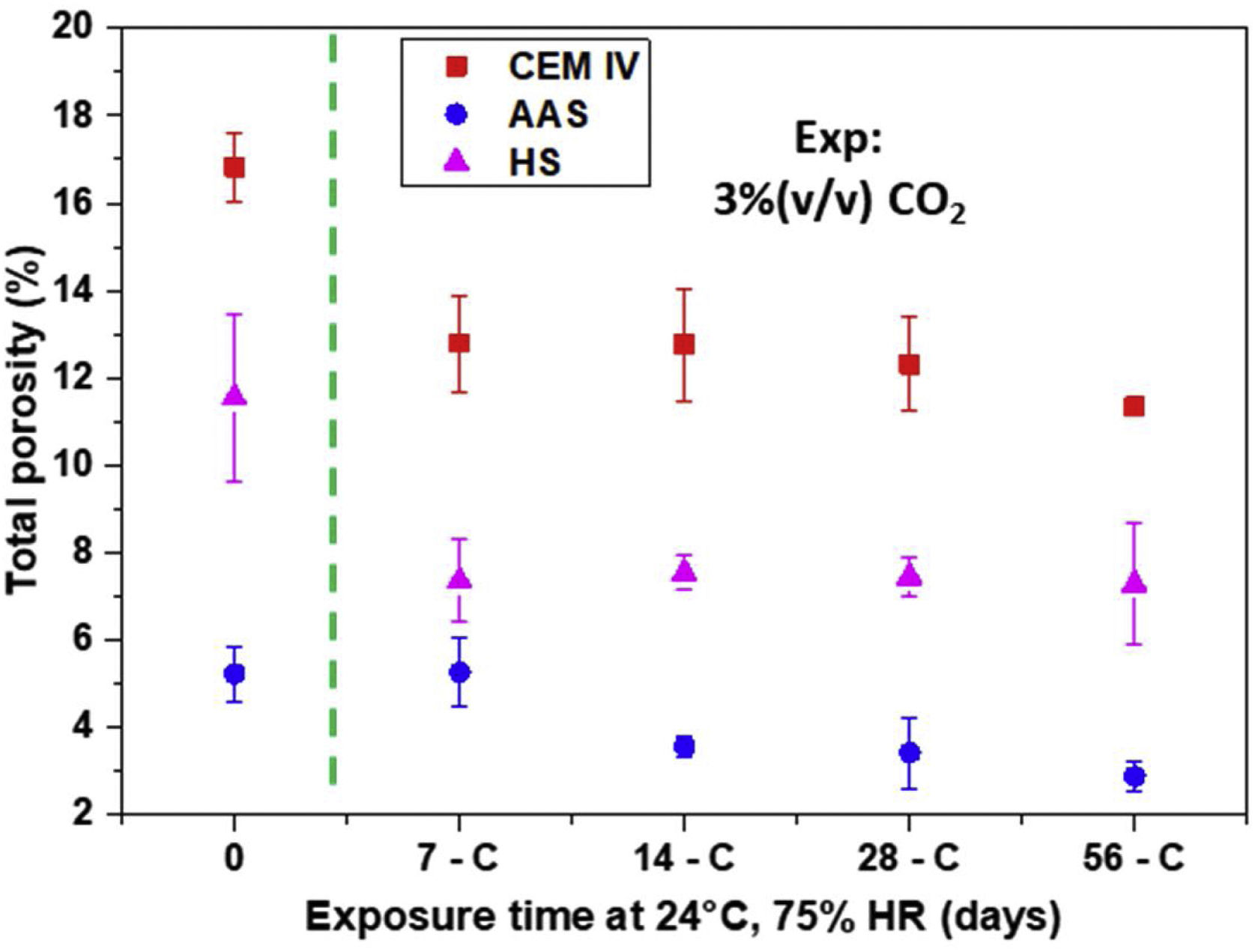
Physical characterization of mortars: total porosity and surface areaAt relative humidities, such as those considered in this study, the carbonation rate is highly dependent on the ability of the CO2 to diffuse through the pores, that is to say, on the pore volume and pore structure of the materials. Fig. 10 shows the porosity values obtained for the mortars under study and the change in the first cm from their surface with exposure time to CO2. Just after curing, the porosity of AAS is the lowest and that of CEM IV the highest, showing an intermediate value for HS. The plotted values, due to the method used for their obtention, reflects the volume of porosity in each material that acts as open porosity for the He penetration (whose volume is somewhat smaller than that of CO2).

The exposure in the carbonation chamber causes a decrease in the porosity for all the mortars (Fig. 10), which could be due to the formation of low-soluble carbonates. However, for CEM IV, the contribution of an unfinished hydration process must also be considered, as previous studies have shown that, during the 28-days curing period, CEM IV has not clearly reached a maximum for its mechanical properties [10]. The results obtained confirm that the initial pH decrease for AAS (Fig. 9) corresponds to a formation of a highly soluble carbonate such as Na2CO3 and no significant decrease in porosity occurs (Fig. 10). At the same time, CaCO3 precipitation occurs in HS and CEM IV (Figs. 4 and 5) with a marked effect not only on the pH but also on the porosity (Fig. 10).
The partial blocking of the pores in the surface clearly limits further CO2 diffusion into the HS and CEM IV. So, the subsequent slower advance of the carbonation (Fig. 9) with time can be understood. The higher porosity of CEM IV (Fig. 10) makes it possible to understand why the amount of CaCO3 formed in the outer layer of CEM IV mortar is higher than in HS (Fig. 2) in spite of HS having the highest calcium content.
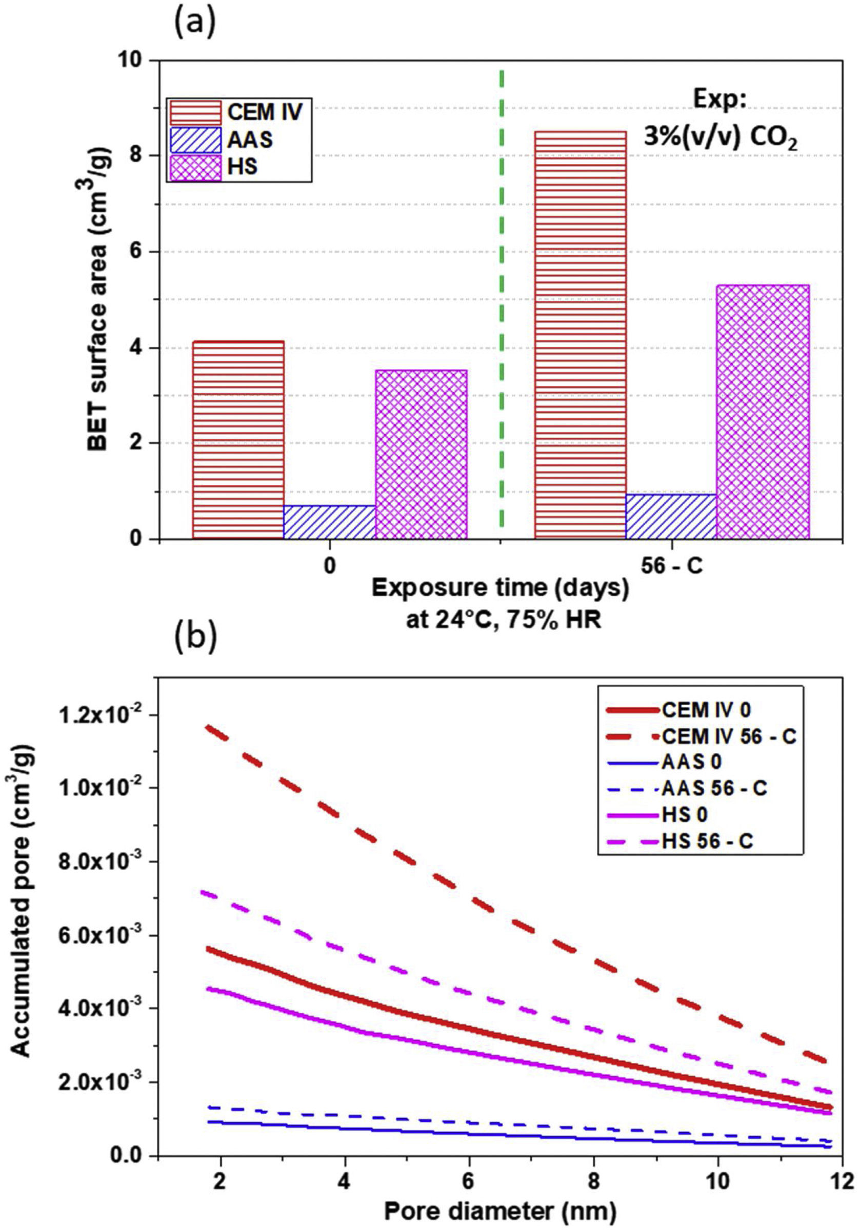
In addition to the total porosity, the surface area of the pores and the volume of accumulated pores (in the range of 12–2nm, which is one studied with BET) of the mortars and their changes have also been examined. The results can be seen in Fig. 11. The exposure in the carbonation chamber causes an increase on the surface area in CEM IV and HS mortars, that is to say, those where a clear decrease in the porosity volume of the outermost layer has been detected after exposure (Fig. 10). This can be related to a decrease in the global open porosity volume due to the carbonate precipitation inside the pores. The formed carbonates split big pores into more numerous, smaller pores (Fig. 11b), which increase the surface area of the mortar (Fig. 11a). It is clear that carbonation reduces the porosity in all mortars, with the mesopores being affected.
Mechanical behavior and wear performance Surface area of mortar pores and (b) accumulated pore distribution of mortars determined from BET.")
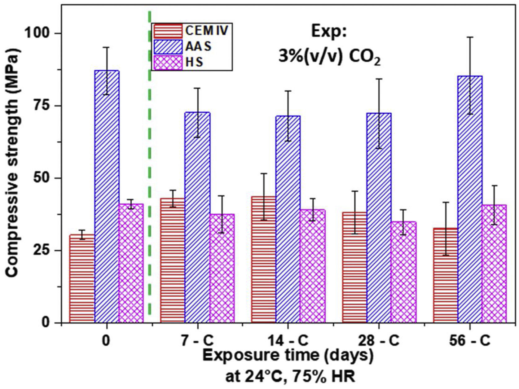
Fig. 12 shows the strength results for all mortars. In the as-cured materials, the effect of porosity is clear, as lower porosity generates more compact microstructure in the mortars, increasing their strengths, due to the formation of a C-A-S-H gel [53]. AAS mortars show the lowest porosity (Fig. 10), thus presenting the highest compressive strength (Fig. 12), which is 65% higher than the resistance presented by the CEM IV mortar. Regarding the HS mortar, its strength is intermediate, between that for CEM IV and for AAS, reaching compressive strengths of around 40MPa. The formation of C-A-S-H gel in HS and in AAS (denser than C-S-H) also contributes to the better mechanical properties of these alternative materials [17]. However, the C-A-S-H gel formed in HS systems is not as rich in silicon as the C-A-S-H gel formed in the AAS system, since sodium silicate is not used as an activator.

With carbonation, all the materials reduce their porosity (Fig. 10) and pore size (Fig. 11). These changes do not provoke marked clear changes on strength (Fig. 12), as the overlapping of the error bars, when occurs, indicates that the differences among mean values show no relevant difference from a statistical point of view and can mainly be related, with a rigorous approach, to the experimental dispersion. Hence, it can be concluded that the chemical and structural changes taking place during carbonation have not had a clear impact on this property for none of the mortars under study. A phenomenon such as decarbonation of C-S-H or C-A-S-H gels can be discarded to a significant extent. The formation of calcium carbonates in the AAS surface from C-A-S-H decalcification suggested in the DTA analysis (Fig. 1b) must have been a very localized process occurring in the outer region. At the same time, in the rest of the sample, CO2 access has been very limited due to the reduced porosity of AAS mortar and the availability of a large amount of sodium hydroxides in the pore solution (Fig. 9) for reacting with CO2.
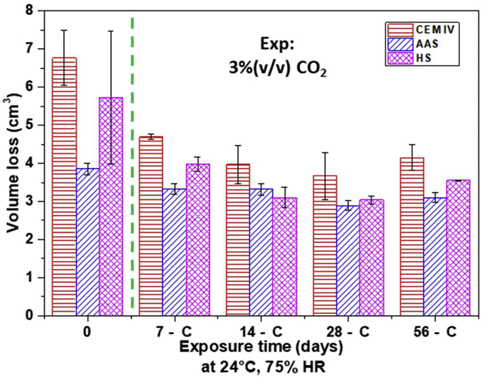
Results of Böhme test (Fig. 13) show that the abrasive wear resistance of non-carbonated HS and AAS mortars is better than that of CEM IV mortar. The lower porosity (Fig. 10) and denser gels formed, besides leading to materials with higher compression strength (Fig. 12), also allows for materials that are more suitable for withstanding wear stresses.

It is important to highlight that wear losses decrease for carbonated mortars. The precipitation of carbonates in the surface pores helps to withstand abrasive wear. There is a clear relationship between the amount of insoluble carbonates formed (Fig. 2) and the improved wear resistance (Fig. 13). The low carbonation suffered by AAS scarcely affects the wear performance of this mortar during carbonation. After the test, AAS continue to be the most abrasion-resistant mortar, but there are fewer differences in the performance of the three materials under study.
ConclusionsThe results of this work allow some interesting and positive conclusions to be drawn about the carbonation performance of alternative binders and this phenomenon's effect on durability. The main conclusions are detailed below:
- •
CRM has led to identification of different carbonates precipitated in the mortars during curing and carbonation conditions. The use of this novel technique (complementary to DTA-TG) allows information to be obtained on the amorphous phases of solid carbonates, as well as quantifying them.
- •
All the mortars under study show rapid pHs decreases in their outermost surface due to CO2 exposure and reaction with the NaOH, KOH, Ca(OH)2 and/or Mg(OH)2, whose solubility controls the alkalinity of the pore solution. AAS mortars, with the lowest porosity, show a much slower progress of the carbonation front.
- •
The changes on the porosity caused by carbonation depends on the nature of the hydroxides previously present in the pore solution of the different mortars. AAS mortars suffer pH decreases on their surface that do not cause proportional pore blocking as most of the formed carbonates are highly soluble.
- •
The wear performance of AAS and HS is better than that of CEM IV mortar not only before and but also after carbonation. The abrasion resistance of all carbonated mortars is improved when non-soluble carbonates are formed inside the surface pores of the mortars, contributing to their plugging. Thus, atmospheric exposure can be positive for materials under these types of loads. This phenomenon also tends to make equal the wear resistance of all the mortars when carbonation proceeds.
- •
No relevant changes in the compression strength of the studied mortars have been observed after the carbonation tests carried out. Decarbonation of structural gels in AAS occurs only to a very limited extent in the surface and barely progresses, so no measurable effect on the mechanical resistance has been detected.
This study was funded by the Ministerio de Ciencia, Innovación y Universidades of Spain through project RTI2018-096428-B-I00 and by the Madrid Government (Comunidad de Madrid) under the Multiannual Agreement with UC3M in the line of “Fostering Young Doctors Research” (HORATSO-CM-UC3M) within the context of the V PRICIT (Regional Programme of Research and Technological Innovation).

