


This work is a post-mortem study of the magnesia-chromite refractory lining of the gas area of a Submerged Arc Furnace (SAF) used for slag-cleaning at the Atlantic Copper Smelter (Spain) after a six-year working campaign. A Scanning Electron Microscope (SEM) equipped with an Energy Dispersive Spectroscopy (ESEM-EDS) system was used to identify the phases and for chemical analysis.
Almost nothing on Submerged Arc Furnace operations in the copper-making industry is found in literature, and none has focused on the interactions of the magnesia-chromite refractory used in the area in contact with gases.
In this work, refractory brick samples were collected from the gas area of a Submerged Arc Furnace that processed fayalitic slag after a six-year campaign. These bricks had been penetrated by gases. Lead and zinc from the gases were found on the hot face of the refractory. The post-mortem analysis was supported by thermochemical calculations using FactSage® databases.
Este trabajo está enfocado al estudio post mortem del refractario usado en la zona de gases de un horno eléctrico de arco sumergido (SAF) donde se han llevado a cabo las operaciones de limpieza de escoria durante seis años de campaña en Atlantic Copper (España). Para la identificación de las fases y los análisis químicos de las mismas se ha usado un microscopio electrónico de barrido (SEM) equipado con un espectrómetro (ESEM-EDS).
En la literatura no se encuentra casi nada publicado referente a operaciones de hornos eléctricos de arco sumergido en la industria del refino del cobre y nada referente a la interacción de los gases de este proceso con el refractario de magnesia-cromita usado en los mismos.
Para este trabajo se han tomado ladrillos de muestra de la zona, de gases de un horno eléctrico de arco sumergido después de seis años de operación de limpieza de escorias fayalíticas (recuperación de cobre). Estos ladrillos refractarios se han encontrado infiltrados por gases. En la cara caliente de lo refractario se ha encontrado plomo y zinc procedente de las fases contenidas en los gases de proceso. El análisis post mortem ha sido complementado con cálculos termodinámicos usando las bases termodinámicas de FactSage®.
The removal of iron sulfur from the concentrates in the smelting and conversion steps of the copper-making process produces fayalitic slag. Initially, the iron sulfur is oxidized and the product that emerges (FeO) is chemically combined with silica, resulting in fayalitic slag (Fe2SiO4). A part of the FeO does not combine with the silica, so magnetite (FeO·Fe2O3, usually represented as Fe3O4) is produced. Thus, the slag is mainly fayalite with different proportions of magnetite, depending on the oxidizing conditions and the iron–silica ratio: in conditions where there is greater oxidation and a higher iron-silica ratio, the fayalitic slag generated in the smelting and conversion steps has a higher magnetite content [1–3].
The slag contains copper species that are the copper losses from this pyrometallurgical process. Usually, the copper contained in the slags is below 2.0wt% for the flash smelting furnace (FSF), and less than 9.0wt% for the Peirce Smith Converters (PSC) [1]. A key step in the copper-making process is the copper recovery from the slag generated in smelting and conversion. To reduce these copper losses in the global process, the slag can be processed via different techniques. One of the most common techniques involves the use of a Submerged Arc Furnace (SAF) into which the slag is introduced in order to settle the trapped sulfide Cu species and reduce the dissolved Cu. To enhance the settling of the copper species contained in the slag, turbulence is minimized, the temperature is increased by using electrodes and the magnetite is reduced as a consequence of the reaction with coal, coke or anthracite to decrease viscosity [1]. The typical content of copper in the outlet slag from a SAF is below 1.0wt%.
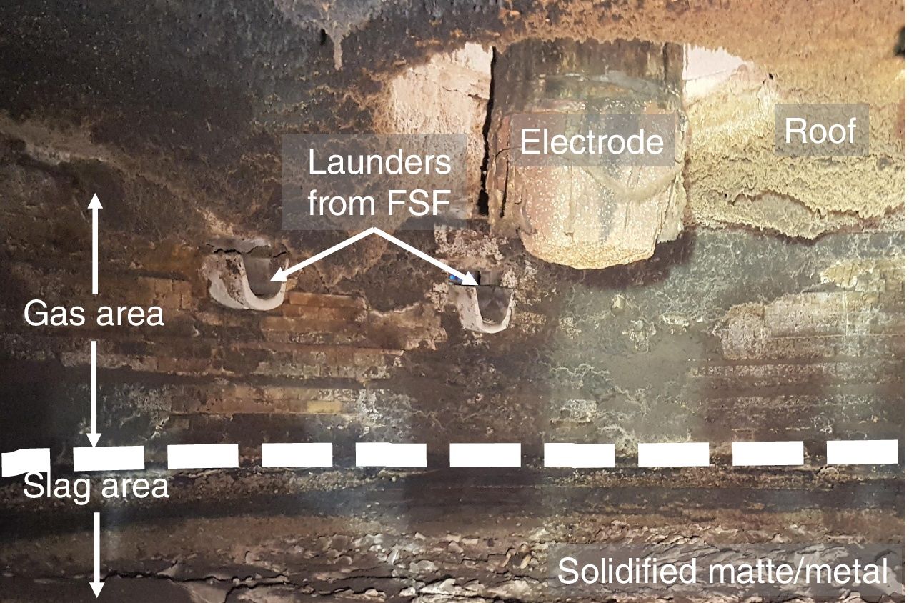
A SAF is a cylindrical furnace (at Atlantic Copper: diameter 11m, height 4m and maximum bath level 2.0m) with 3 electrodes, launders to charge the slag from the smelting and converting furnaces, and to tap the processed slag (final cleaned slag). This type of furnace is lined with magnesia-chromite refractory bricks (Fig. 1), and spray water is used to refrigerate the walls (outside the external shell). In operation, the gas is continuously drafted through a duct located on the roof, using a fan (the typical draft is −1.0mmca). The gases are usually cleaned of dust and some low SO2 content in a scrubber.
. The refractory is in contact with gas, slag and matte/metal depending on the height (separated by dotted lines).")
Refractories are materials capable of maintaining good thermal, chemical and physical characteristics at high temperature. These features determine the length of refractory life during service in campaigns. The refractory lining of a SAF is usually replaced every 3–6 years because of wear in the area in contact with the slag phase. By contrast, according to industrial experience, the refractory wear of the lining in contact with the gas phase is very low, so the degradation of the lining located in this area does not limit the lifespan of a SAF working campaign. We found no published work in the literature on the wear of the magnesia-chromite refractory used in the gas area in a SAF.
The most widely used refractory in the copper-making industry is the magnesia-chromite type [4–13] due to its superior performance-cost ratio. It is made of electrofused magnesia-chromite (EMC), dead-burned magnesia and chromite ore. The grains of these raw materials are usually direct bonded in the internal microstructure of the refractory [6,11,13,14].
Some authors highlight the capacity of the magnesia-chromite refractory to counter the degradation mechanisms that lead to refractory wear [4,6,7,10–13,15,16]. The main objectives of the refractory industry are to increase resistance to: chemical degradation by the molten phases, abrasion resulting from the bath movement inside the furnaces, and thermal and mechanical shocks [4].
Refractory wear has been studied by simulation with finite element models (FEM), thermodynamic databases (thermochemistry) [4,17–22], multiphysics modeling [8,23–29], laboratory tests under static or dynamic conditions [9,30–35] and industrial post-mortem analysis after a working campaign [4,6,11–13,36–41]. The latter provides the most valuable information because it shows refractory behavior in real working conditions.
This work studied the degradation of the refractory in contact with pyrometallurgical gases in a SAF. Samples from different locations in the gas area along the perimeter were collected from an industrial SAF at Atlantic Copper (Huelva, Spain) after a six-year working campaign (May 2011–2017). During this time, 4.5 mill. tons of slag were processed from a FSF and PSC. The microstructure of the samples was studied by using SEM-EDS and EPMA.
Materials and methodsSampling and sample preparationSampling was carried out in May 2017 at the end of a six-year SAF working campaign. Eight samples were collected from different locations along the furnace perimeter, but only from the area in contact with the gas during the operation. This area had not been in contact with the slag at any time during the six-year operation; only the gas had been in contact with the sample area. Fig. 1 shows the wall of the SAF during the sampling works once the SAF had cooled down.
Each sample stood at a perimeter distance of 90°, and two samples at different vertical levels at each perimeter location were collected.
A central slide, perpendicular to the hot face, was cut from each sample to obtain the final samples for analysis (Fig. 2, left). These final samples were polished and prepared for microstructural analyses according to standard methods.
Analytical methods
Microstructural characterizations of the samples were performed using a Scanning Electron Microscope (SEM) FEI-QUANTA 200 at the University of Huelva. The SEM is equipped with an Energy Dispersive Spectroscopy (ESEM-EDS) system. The accelerating voltage is 0.2–30kV with a resolution of 3.5nm. It has a solid-state backscattered electron detector (SSD) to determine the compositional difference, a secondary Everhardt Thornley detector (ETD) to enable viewing of the surface image and an X-ray dispersion digital microanalysis system (EDAX Genesis 2000) with SiLi detector for quantitative analysis.
Additionally, an Electron Probe Micro-Analyzer with a wavelength-dispersive spectrometer (EPMA-WDS) JEOL model JXA-8200 was used to obtain accurate analyses. The accelerating voltage is 15kV, current 20nÅ and spot equal to 1.0–5.0μm.
Both pieces of analytical equipment (ESEM-EDS and EPMA-WDS) are property of the University of Huelva.
To support the analytical results, thermochemical calculations were carried out using the thermodynamic databases of the FactSage® 7.1. software [19,20]. FactSage® is based on thermochemistry, mainly in relation to complex phase equilibria. The software is divided into modules that allow the user to calculate thermochemical equilibria and phase diagrams in different conditions by means of a general Gibbs energy minimization algorithm, with access to the internal thermochemical databases. The thermochemical databases used for this work were FT oxide, FT misc and FACT PS.
The methodology used to carry out the thermochemical calculations was the following:
- -
The temperature selected was 1165°C as it represented the real conditions of the furnace in operation. The value of temperature was obtained from real data recorded by operators.
- -
Chemical analysis of the final slag from the SAF was performed and then compared to historical data. The oxygen potential (pO2) of the system was estimated using these characteristic compositions of the final slag produced in the furnace.
- -
Since the SAF working operation involves the cleaning of the FSF and PSC slags in reducing conditions by adding petroleum coke, these operating conditions were simulated. The proportion of the slag from the FSF and PSC was obtained from real data (83:17 respectively), and the amount of coke added was estimated using as a reference the working pO2 obtained previously. Under these pO2 conditions, the composition of the gas was estimated using thermochemical calculations.
- -
Gas condensation was simulated: the condensed species were identified and the condensation fraction estimated.
- -
The thermochemical results (the fraction of species formed during the condensation) were compared to the microstructural analysis of the refractory samples.
Near the electrodes and surface of the bath where the coke was floating, there was expected to be a decrease in pO2 and increase in the temperature, so a parametrization of the thermochemical calculations under different conditions was made using different pO2 (5E−11 and 5E−10atm.) and temperatures (1200°C).
Results and discussionThe abbreviation of the species in this work is presented according to the international standard [42].
As-delivered refractory bricks at micro scaleThe study of the original refractory prior to the post-mortem analysis is common among authors [4,6,9,13,43,44]. There are two main refractory-making procedures: electrofusion, and agglomeration of grains/particles. Since electrofused refractories are highly sensitive to thermal shocks, they are used in the glass industry (an intensely continuous operation). The refractory used in the copper-making process is produced by grain/particle agglomeration, with a final firing step.
The chemical composition of the refractory bricks analyzed in this work was (from the supplier datasheet): 56.6wt.% MgO, 21.0wt.% Cr2O3, 12.5wt.% Fe2O3, 7.5wt.% Al2O3, 1.3wt.% SiO2 and 1.1wt.% CaO; porosity is 17.5vol.%, and apparent density 3.20g/cm3.
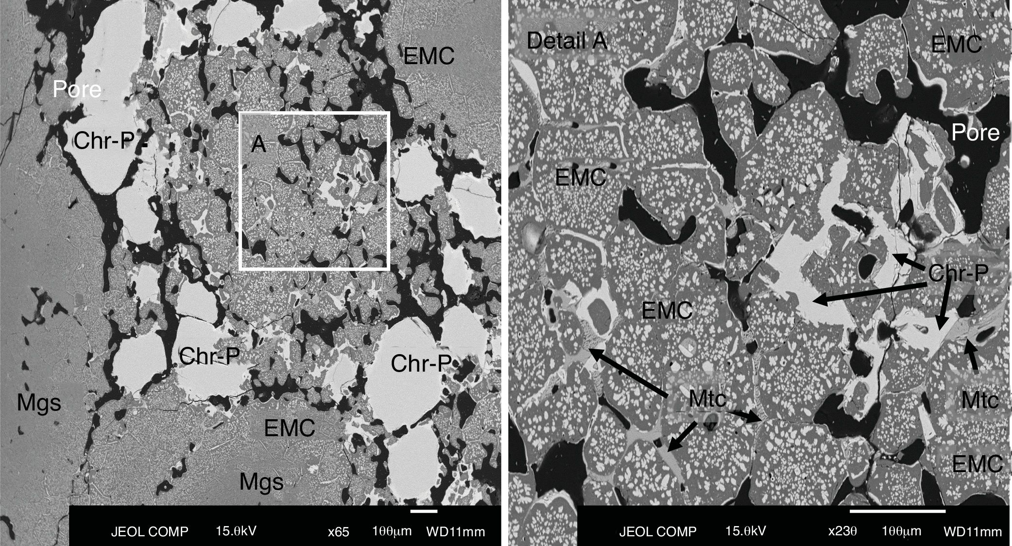
The microstructural analysis of the as-delivered refractory (Fig. 2) carried out in this work showed that the phases in this refractory were: chromite spinel [Mg(Cr,Fe,Al)2O4], magnesia/periclase (MgO, Mgs), electrofused magnesia-chromite (EMC) and monticellite (CaMgSiO4, Mtc) in the intergranular areas (Fig. 2). This matches the information in the supplier datasheet on the raw materials used for making this type of refractory bricks.
Chromite is present in the samples as grains (primary chromite; Chr-P in Fig. 2), meaning that the chromite has not been modified by the firing step of the refractory-making process and, as secondary chromite (Chr-S), it is located in the intergranular regions among the grains of the microstructure [6,9,45]. The secondary chromite has acquired the shape of the intergranular area that it fills, and the proportion of this secondary chromite is quite low compared to the primary chromite.
The electrofused magnesia-chromite (EMC) is the most abundant phase in the microstructure and is present as grains of multiple sizes. The EMC is found as large single grains, multiple grains that are directed bonded or joined by secondary chromite or monticellite (Mtc in Fig. 2 detail A), or as a rim around the magnesia grains (Mgs in Fig. 2). The EMC is composed of a MgO-rich matrix and a dispersed phase (chromite) (Fig. 2). Magnesia grains are found with a rim of EMC.
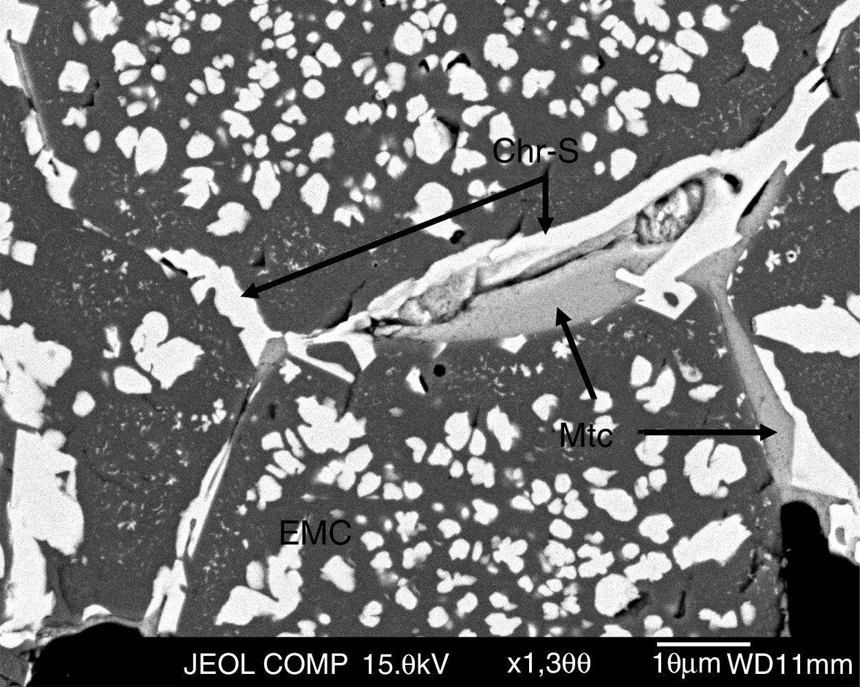
The grains (EMC, chromite and magnesia) are direct bonded but, in many cases, secondary chromite and monticellite fill the intergranular areas among the grains [6,13,16,46] (Fig. 3).

BSE image of the as-delivered refractory used in the lining of the area of the SAF in contact with the gases. Detail of the intergranular area filled with secondary chromite and monticellite. Abbreviations: EMC, electrofused magnesia-chromite; Chr-S, secondary chromite; Mtc, monticellite.
During the firing step of the brick-making process, monticellite forms as a consequence of impurities in the raw materials (silicates). The low monticellite content in the refractory analyzed in this work is proof of the high purity of the raw materials used in the brick-making process.
The BSE images reveal the presence of pores in the microstructure. They are abundant (in line with the datasheet; 17.5vol.%) and prevent the grains from bonding so that the penetration of the molten or gas phases from the furnace can take place. The control of grain size distribution (an appropriate proportion of grains of different sizes) and the agglomeration and pressing processes are designed to minimize porosity in the final refractory brick. The better the performance of these aspects of the refractory-making process, the lower the porosity of the final refractory produced. In this case, porosity is 17.5vol.%, a standard value as the porosity of commercial refractories usually falls within the 10–25vol.% range [13].
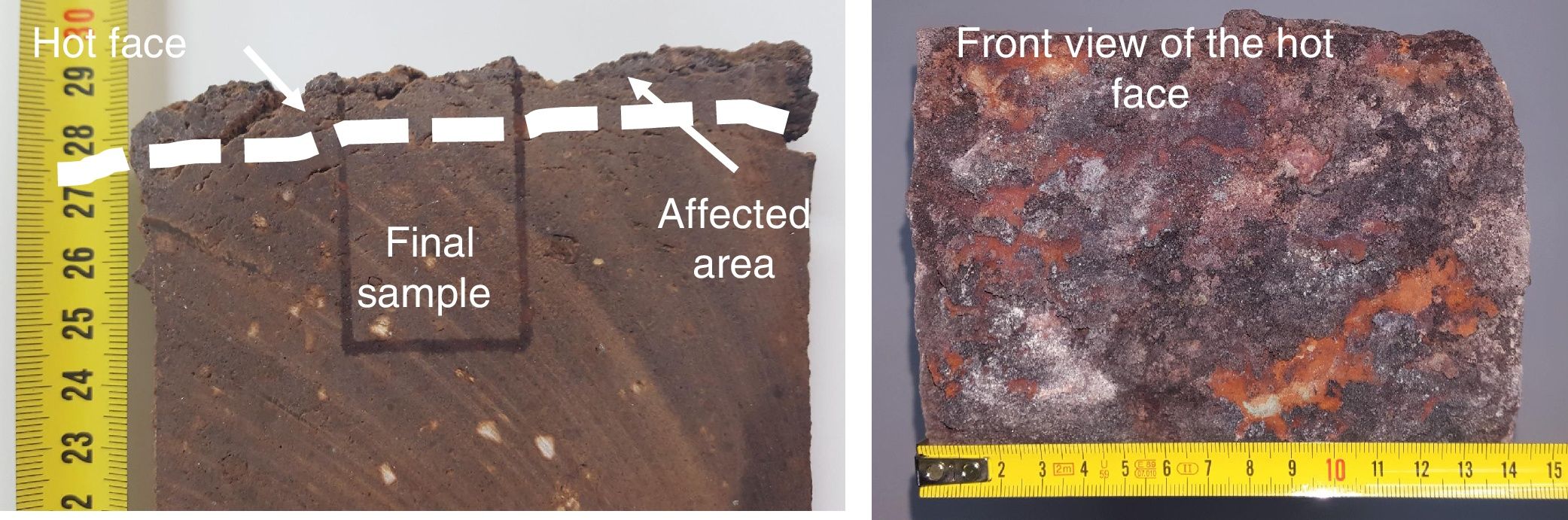
Industrial-worn refractory bricks at macro scaleThe wear was very limited when compared to the refractory in the area in contact with the slag. The as-delivered refractory brick in the gas area was 350mm length and the length (average) of the sampled bricks at the end of the campaign was 278mm (20.6% reduction); the minimum being 255mm and the maximum 310mm. In the case of the slag area, the wear decreased the length of the refractory by 75.6% (the original length was 550mm) [12]. According to these data and the length of the working campaign (6 years), the velocity of the wear was estimated at 12mm per year (average).
Macroscopically, the area affected by the gas phase on the hot face of a brick was very thin but clearly differentiated from the non-affected area (Fig. 4). Hence, the effect of the gas is clearly noteworthy. The thickness of this affected layer varies within the range of 10–20mm, and cracks parallel to the hot face were visible (not filled with material).
. The dotted line separates the affected area from the rest of the refractory brick (unaffected by the gas), and the final sample for microstructural analysis is shown. Right: Frontal view of the same refractory brick.")
Left: detail of the affected area on the hot face of a refractory brick collected in this work (cut slide). The dotted line separates the affected area from the rest of the refractory brick (unaffected by the gas), and the final sample for microstructural analysis is shown. Right: Frontal view of the same refractory brick.
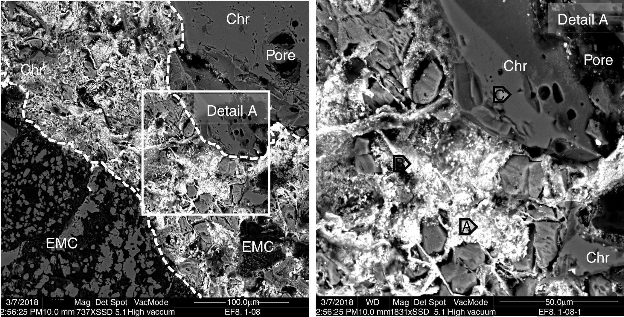
The microstructural analysis of the worn refractory shows that in the areas close to the hot face of the refractory, the gas penetrated the refractory through the open pores and micro-cracks. The phases that initially filled the intergranular areas in the as-delivered refractory are not present, and they were filled (together with the pores and micro-cracks) with the products of the condensation of the penetrated gas and the possible reaction with the intergranular phases (Figs. 5 and 6), due to their low melting point (mainly monticellite).
 are shown in Table 1.")
BSE image of the hot face of a magnesia-chromite refractory penetrated by gas from the SAF. The penetrated area is shown between dotted lines. The points analyzed (A, B and C) are shown in Table 1.
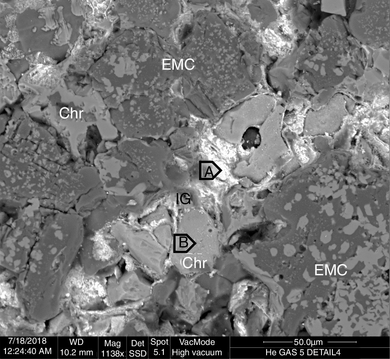
 are shown in Table 1.")
BSE image of the hot face of a magnesia-chromite refractory penetrated by gas from the SAF. IG: penetrated gas from the SAF. The points analyzed (A and B) are shown in Table 1.
The inner areas did not suffer gas penetration (>15mm behind the hot face). The BSE images show that the penetration capacity of the gas sharply decreased beyond 12–15mm from the hot face, and only traces of high-lead content phases were found among the refractory grains in the intergranular areas (Fig. 7). The composition of these traces is similar to the penetrated phases but just on the hot face: compare point A in Fig. 7 to point A in Fig. 5 or points C, D, E in Fig. 6.
.")
BSE image of the area of the refractory brick located just behind the hot face. White dots represent penetrated phases with high lead content from the SAF gas (the result of the analyzed point A is in Table 1).
From the BSE images, it is clear that the refractory grains were not chemically modified by the gas from the SAF. Even the boundary separating the different types of refractory grains (EMC, chromite and magnesia) in contact with the gas phase maintained the same structure and chemical composition as the inner areas; no reaction rims were found (see Fig. 5 detail A and Fig. 6). The analysis of the penetrating phase shows that no significant number of refractory elements were present (Table 1); it is proof that they did not dissolve in this penetrating phase. This differs from the slag penetration that clearly provoked the dissolution of the magnesia phases and the ionic exchange in the spinel phases (Fe-Mg) [4,6,7,9–12,38,47–49].
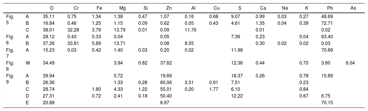
Chemical composition of the points analyzed in Figs. 5–7 and 9. The data W in Fig. 8 corresponds to the analysis of the entire BSE image (windows analysis). Units in wt.%. The corresponding species of the analyzed points of the gas penetrated are in Table4.
| O | Cr | Fe | Mg | Si | Zn | Al | Cu | S | Ca | Na | K | Pb | As | ||
|---|---|---|---|---|---|---|---|---|---|---|---|---|---|---|---|
| Fig. 5 | A | 35.11 | 0.75 | 1.34 | 1.38 | 0.47 | 1.07 | 0.16 | 0.68 | 9.07 | 0.99 | 0.03 | 0.27 | 48.69 | |
| B | 16.84 | 0.46 | 1.25 | 1.15 | 0.09 | 0.62 | 0.05 | 0.43 | 4.61 | 1.35 | 0.04 | 0.39 | 72.71 | ||
| C | 38.01 | 32.28 | 3.79 | 13.79 | 0.01 | 0.09 | 11.76 | 0.01 | 0.02 | ||||||
| Fig. 6 | A | 28.12 | 0.43 | 0.33 | 0.04 | 0.05 | 7.36 | 0.23 | 0.04 | 63.40 | |||||
| B | 37.26 | 33.81 | 5.89 | 13.71 | 0.08 | 8.55 | 0.30 | 0.02 | 0.02 | 0.03 | |||||
| Fig. 7 | A | 15.23 | 0.03 | 0.42 | 1.40 | 0.03 | 0.20 | 0.02 | 11.98 | 70.69 | |||||
| Fig. 8 | W | 34.49 | 3.94 | 0.82 | 37.62 | 12.36 | 0.44 | 0.70 | 3.60 | 6.04 | |||||
| Fig. 9 | A | 39.94 | 0.72 | 19.69 | 18.37 | 0.26 | 0.78 | 15.89 | |||||||
| B | 26.36 | 1.33 | 0.28 | 60.06 | 3.31 | 0.91 | 7.51 | 0.23 | |||||||
| C | 28.74 | 1.80 | 4.33 | 1.22 | 55.01 | 0.20 | 1.77 | 6.10 | 0.84 | ||||||
| D | 27.31 | 0.72 | 2.41 | 0.18 | 50.40 | 12.22 | 0.67 | 6.75 | |||||||
| E | 20.88 | 8.97 | 70.15 |
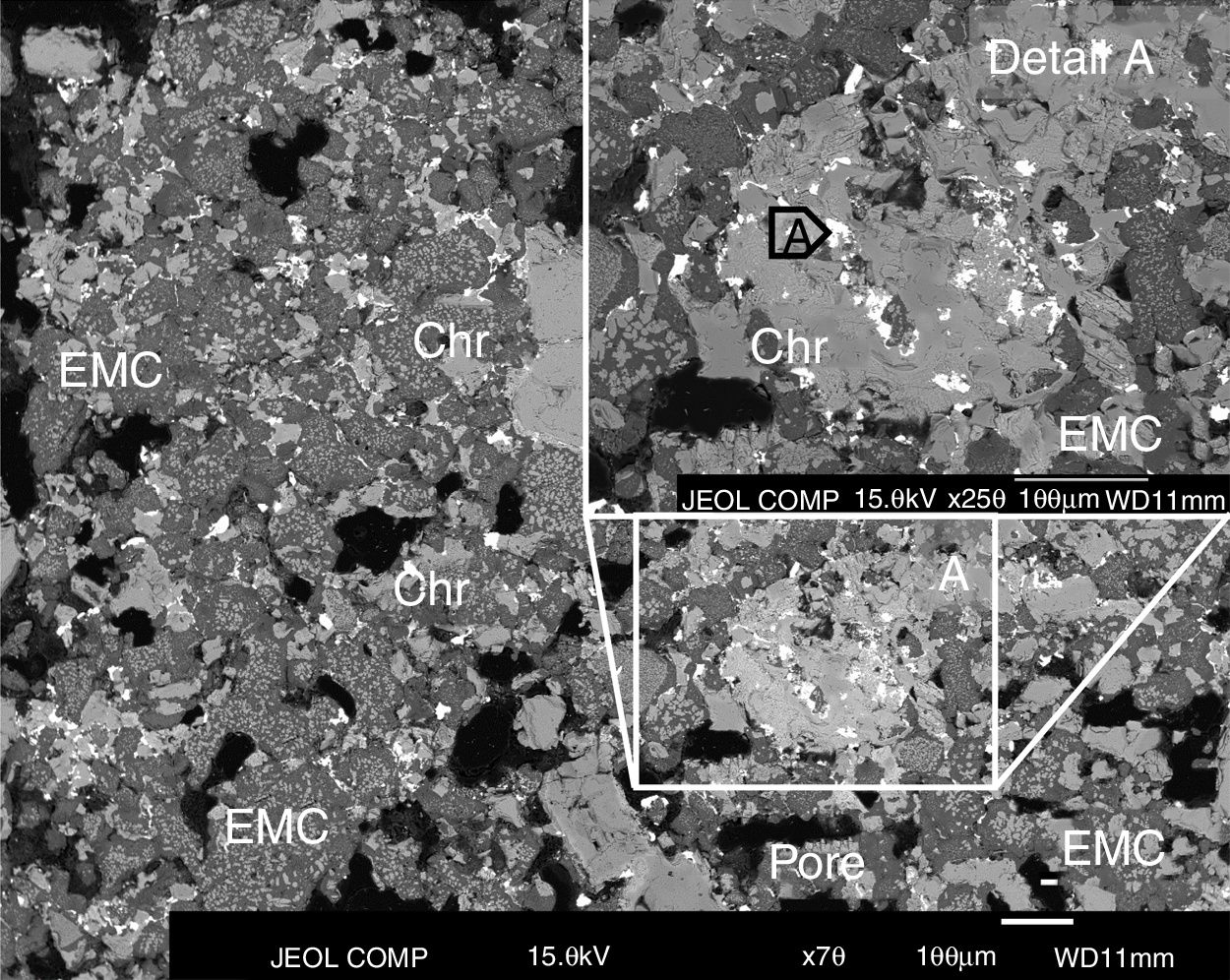
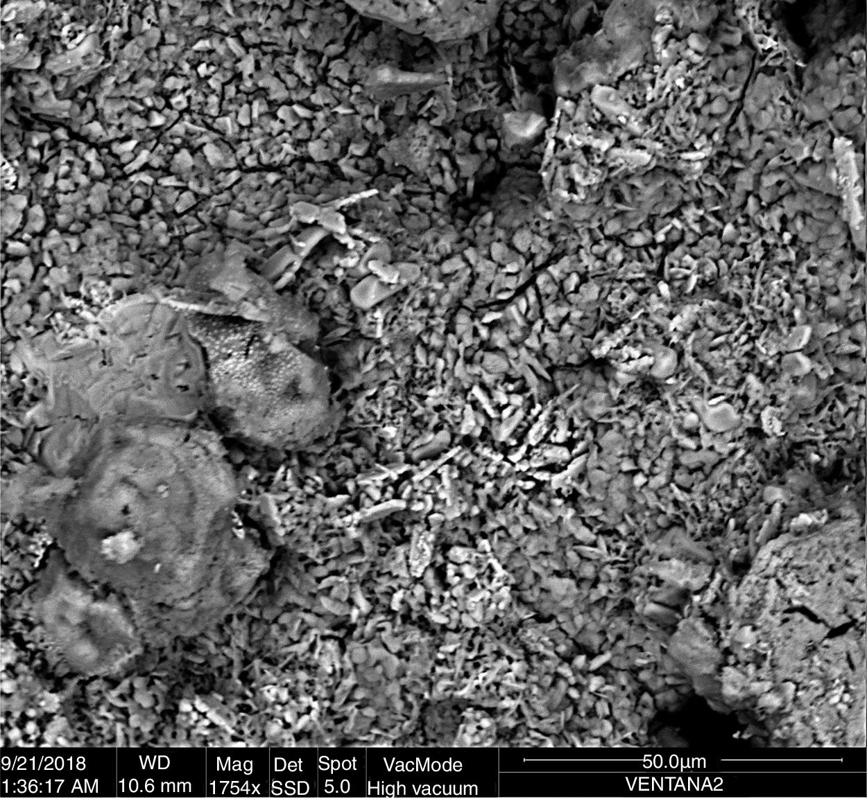
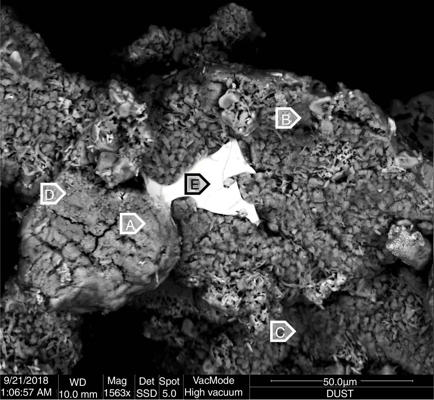
Lead and zinc are the main elements of the phases in the penetrated areas. These phases came from the condensation/solidification of the penetrating gas. Lead-containing species were found in deeper areas of the hot face in the intergranular areas and open pores, but zinc-containing species were only mainly found on the hot face. The analysis of the BSE images of the material obtained just on the hot face shows condensed species from the gas generated in the SAF (Figs. 8 and 10; points analyzed in Table 1). From this microstructural analysis, it is evident that the zinc-containing species are the most predominant on the external areas of the hot face. The penetrated species on the hot face contain a high proportion of lead, and the zinc is clearly reduced (compare analyzed points A and B of Fig. 5, A of Fig. 6 and A of Fig. 7 to analyzed points of Figs. 8 and 9).
.")
BSE image of the material collected from the hot face of the refractory brick samples located in the gas area of the lining of the SAF. An analysis of the hole image was carried out and the result is shown in Table 1 (analyzed point W, window).

BSE image of the material collected from the hot face of the refractory brick samples located in the gas area of the lining of the SAF. The points analyzed are indicated, and the results are shown in Table 1.
The pO2 of the system is 1.30E–10atm. at 1165°C, according to the slag composition and the thermochemical analysis carried out. The composition of the slag used for this calculation was the final slag of the SAF (Table 2).
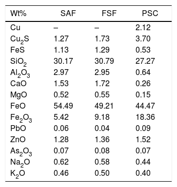
Chemical composition (wt%; normalized) of the slag from the Flash Smelting Furnace (FSF), Submerged Arc Furnace (SAF) and the Peirce–Smith Converters (PSC) used for thermochemical calculations.
| Wt% | SAF | FSF | PSC |
|---|---|---|---|
| Cu | – | – | 2.12 |
| Cu2S | 1.27 | 1.73 | 3.70 |
| FeS | 1.13 | 1.29 | 0.53 |
| SiO2 | 30.17 | 30.79 | 27.27 |
| Al2O3 | 2.97 | 2.95 | 0.64 |
| CaO | 1.53 | 1.72 | 0.26 |
| MgO | 0.52 | 0.55 | 0.15 |
| FeO | 54.49 | 49.21 | 44.47 |
| Fe2O3 | 5.42 | 9.18 | 18.36 |
| PbO | 0.06 | 0.04 | 0.09 |
| ZnO | 1.28 | 1.36 | 1.52 |
| As2O3 | 0.07 | 0.08 | 0.07 |
| Na2O | 0.62 | 0.58 | 0.44 |
| K2O | 0.46 | 0.50 | 0.40 |
According to the BSE images obtained in this work (Figs. 5–7), the refractory lining suffers from gas penetration that leads to the condensation of lead and zinc from the gas, which is concentrated on the hot face, pores, cracks and intergranular areas of the structure of the refractory.
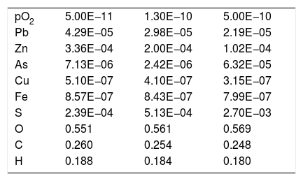
Taking the chemical composition of the slag at 1165°C and pO2 equals to 1.30E–10, the composition of the gas was obtained (Table 3). The main component of the gas was CO2 and CO, as a result of the coke addition to the furnace as chemical reducer for the reaction with Fe3O4 (pO2 is reduced to facilitate the reduction of the magnetite in order to boost the slag-cleaning process). The CO2 and CO do not chemically modify the furnace's refractory lining.
Composition (mole fraction) of the gas from the SAF obtained by thermochemical calculation (FactSage® databases) at different pO2 (atm.).
| pO2 | 5.00E−11 | 1.30E−10 | 5.00E−10 |
| Pb | 4.29E−05 | 2.98E−05 | 2.19E−05 |
| Zn | 3.36E−04 | 2.00E−04 | 1.02E−04 |
| As | 7.13E−06 | 2.42E−06 | 6.32E−05 |
| Cu | 5.10E−07 | 4.10E−07 | 3.15E−07 |
| Fe | 8.57E−07 | 8.43E−07 | 7.99E−07 |
| S | 2.39E−04 | 5.13E−04 | 2.70E−03 |
| O | 0.551 | 0.561 | 0.569 |
| C | 0.260 | 0.254 | 0.248 |
| H | 0.188 | 0.184 | 0.180 |
In thermochemical terms, the main elements from the slag in the gas were Zn and Pb (Table 3), and this result matches the analysis of the samples collected from the furnace (Figs. 5–9 and Table 1). Moreover, the thermochemical results show that the species present in the gas were Zn (5.75E–02mole%), PbS (4.94E–03mole%), Pb (3.65E–3mole%), PbO (1.33E–05mole%) and ZnS (3.52E–06mole%) at 1165°C and pO2 equal to 1.30E–10atm. The main compounds of the gas were generated as a consequence of coke combustion; the proportion of the compounds were estimated from the following thermochemical calculations: 63.30mole% CO2, 24.81mole% H2O and 9.97mole% CO.
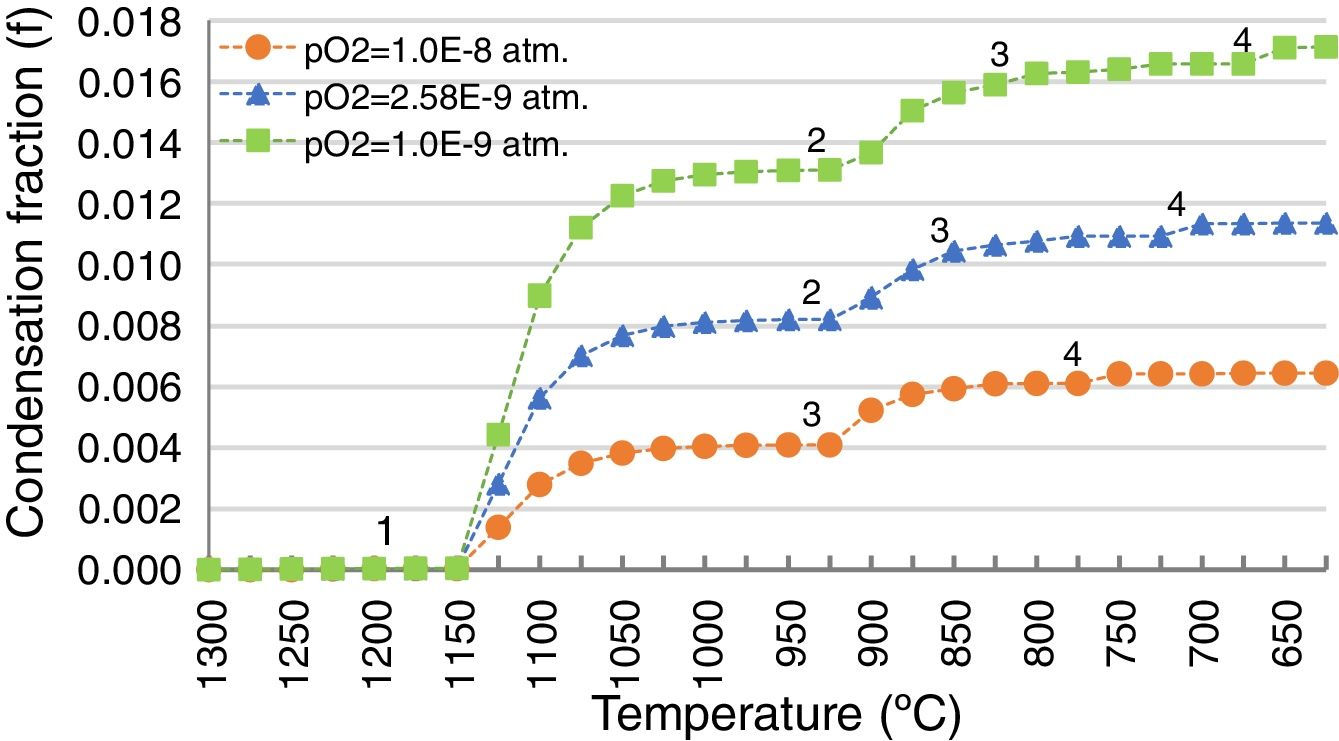
Since penetrated species from the gas in the refractory were found in the microstructural analysis (Figs. 5–9), thermochemical calculations simulating the condensation process were carried out to evaluate this process theoretically. These calculations show that the condensation process of the gas from the SAF follows the described path when decreasing the temperature: the first specie to condensate is ZnO(s), followed by PbO(s), (PbO)xPbSO4(s) and finally PbSO4(s) (Fig. 10). This suggests that the Zn-containing condensed species are to be found in areas closer to the hot face; it matches the microstructures of the material collected on the hot face of the refractory (Figs. 8 and 9). And the Pb-containing condensed species are expected to be found in inner areas, as is shown in Figs. 5–7.
 indicate the initiation of the condensation of each specie: 1, ZnO(s); 2, PbO(s); 3, (PbO)x PbSO4(s); 4, PbSO4(s). Calculated using FactSage® databases.")
Additional scenarios at different pO2 were simulated because fluctuations in the pO2 could happen in the process due to the different relative amounts of coke-slag within the SAF, or due to the intake of false air through the holes in the walls enabled for the inlet launders. The gas generated under these different pO2 conditions (5E–10 and 5E–11atm.) was calculated (Table 3) and the condensation fraction when decreasing the temperature was estimated (Fig. 10).
The path of the condensation fraction at different pO2 is similar in shape to the one previously calculated at 1.3E–10atm, but the condensation of each pointed species takes place at a different temperature: the lower the pO2, the later each specie condensates (Fig. 10). In the case of higher pO2 (5E–10atm.), the PbO does not condensate.
By contrast, the amount of the condensed species is higher for lower pO2 (Fig. 10). Hence, it is demonstrated that gas penetration in the refractory is greater for lower pO2 scenarios, because the amount of condensed species from the gas is higher, and the condensation of the different species happens at lower temperatures.
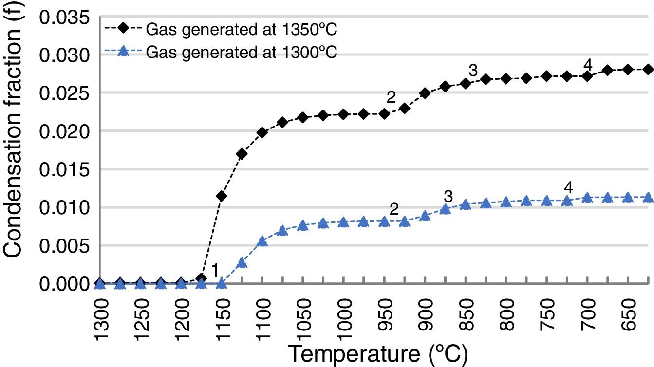
The slag-cleaning process in the SAF is a bath process, so temperature fluctuations occur. To estimate the impact of these fluctuations on the penetrating capacity of the gas from the SAF in the refractory lining, the thermochemical calculations described in this work were applied to an additional scenario at a different temperature: 1200°C instead of 1165°C. All other conditions were the same (pO2=1.30E−10, FSF:PSC slag ratio 83:13 and composition of the FSF and PSC slags). The result was compared to the scenario at 1165°C (Fig. 11) and it was demonstrated that the amount of penetrated species was bigger as a consequence of the higher proportion of Zn and Pb in the gas of the SAF (2.47 and 1.79 times higher respectively); the amount of gas is the same for these temperatures.
. The points (1, 2, 3, 4) indicate the initiation of the condensation of each specie: 1, ZnO(s); 2, PbO(s); 3, (PbO)x PbSO4(s); 4, PbSO4(s). Calculated using FactSage® databases.")
Condensation fraction of the gas generated in the SAF at pO2=1.30E−10atm. and at different temperatures (1165 and 1200°C). The points (1, 2, 3, 4) indicate the initiation of the condensation of each specie: 1, ZnO(s); 2, PbO(s); 3, (PbO)x PbSO4(s); 4, PbSO4(s). Calculated using FactSage® databases.
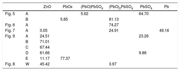
The condensed species were determined using the analytical data from the BSE images (Table 1) and the thermochemical databases of FactSage®. The species with Zn and Pb were the most abundant (Table 4).
Species with Zn and Pb of the points analyzed in Table 1. Calculated using thermochemical calculations with FactSage (units in wt.%).
The thermodynamic evaluation of interactions between the lining and the gases during the operation of the SAF using Factsage® databases showed that no chemical reactions occurred at 1165–1200°C, with pO2 varying between 5.0E−11 and 5.0E−10. These results are in line with what is known about the chemical corrosion mechanisms of the constituent phases of refractory with molten phases, where the magnesia dissolution in the fayalitic slag and the ionic exchange of the Fe-Mg between the spinel phase and the fayalitic slag are the main mechanisms identified [4,11,13,49].
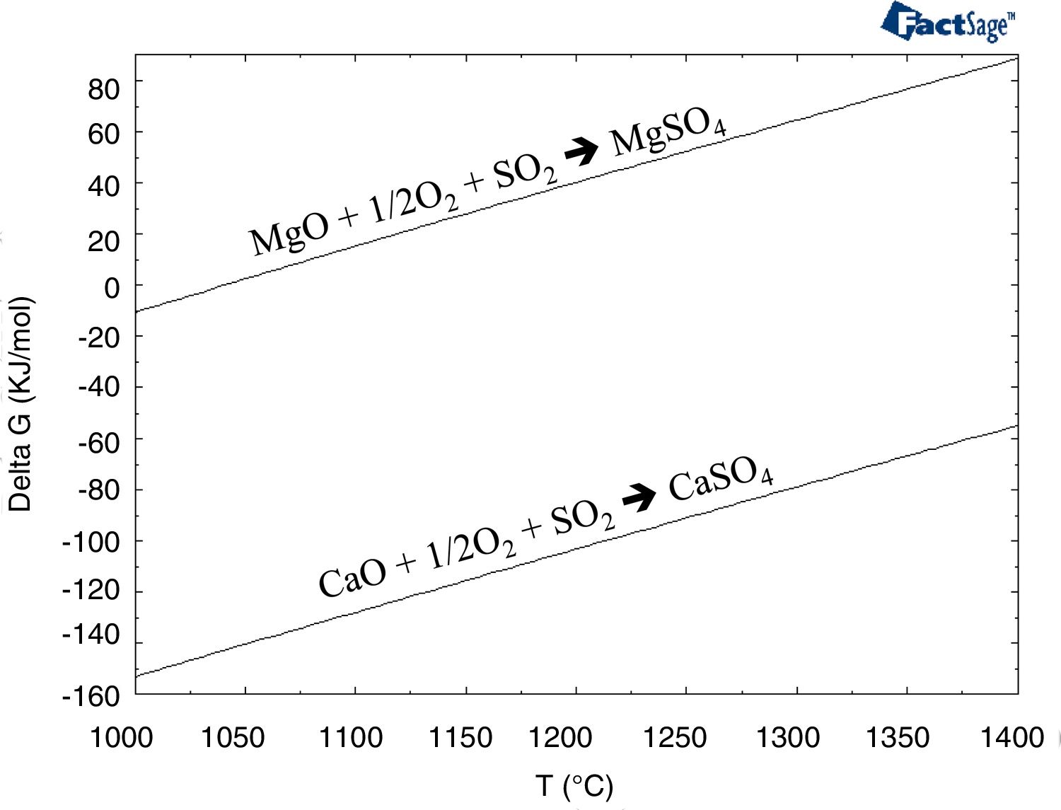
Few authors have studied the interaction between a gas and the refractory [50,51]. The main conclusion of these works are that the SO2–O2-containing gas at high temperature (>700°C) causes changes in refractory composition. The reaction products are the stable sulfate compounds: MgSO4, CaSO4 and CaMg3(SO4)4. They proceed to disintegrate various phase structures and, consequently, cause refractory erosion because of the evident volume increase resulting from these reactions. The degradation of the refractory is due to the following: the lime-containing phases (mainly monticellite as an impurity located in the intergranular areas) dissociate, and the recrystallized CaO reacts with the SO2 of the gases to form CaSO4 (and MgSO4) according to the following reactions (Eqs. (1) and (2)). The presence of water vapor in the gas could accelerate these reactions) (Eqs. (1) and (2)) [50]:
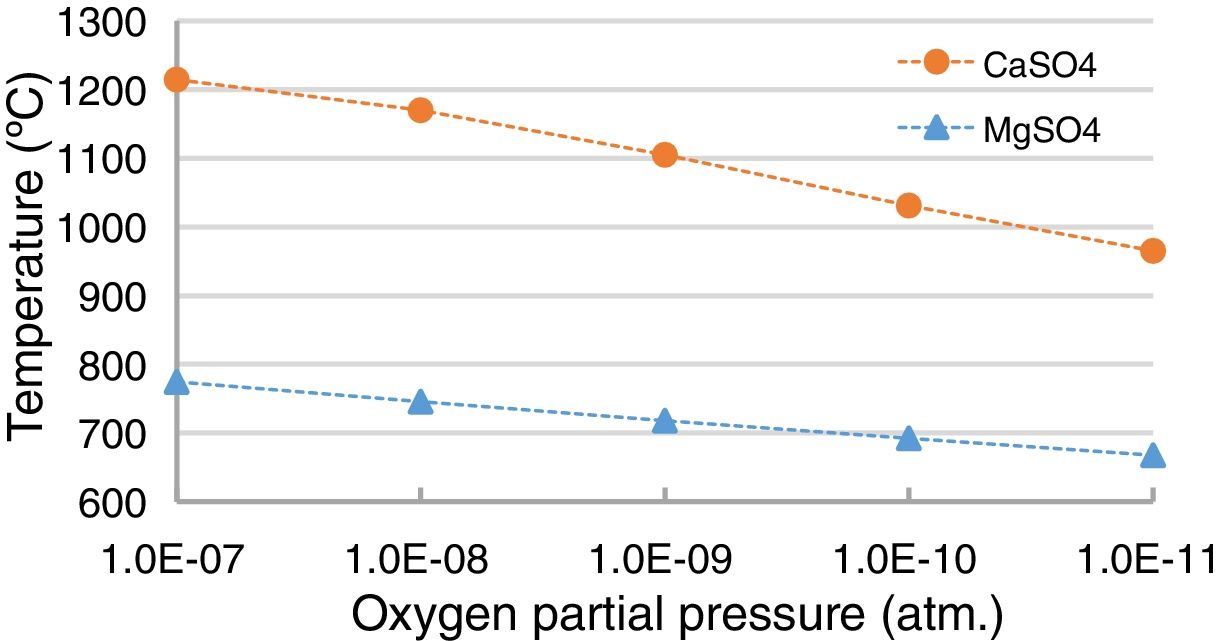
Thermochemically, the reaction with the lime (Eq. (1)) is more favored than the reaction with the magnesia (Eq. (2)) (thermochemical results in Fig. 12). Under SAF conditions (pO2 equals 1.30E–10atm.), the MgSO4 is stable for temperatures up to 692.9°C, while CaSO4 is stable up to 1033.5°C. However, the variation in the pO2 influences this temperature [52–54], and this was evaluated using the thermochemical calculations in this work (Fig. 13); the lower the pO2, the lower the temperature for the CaSO4 and MgSO4 to be stable. This variation is greater for CaSO4 than for MgSO4.
 and (2)) versus temperature.")
Gibbs free energy for the reactions between CaO and MgO with SO2 (Eqs. (1) and (2)) versus temperature.

Hence, CaSO4 and MgSO4 are expected to be formed when the SO2-containing gas penetrates the refractory bricks in the copper-making furnaces. Since the operation of the SAF is to clean the slag from the FSF and the PSC, the SO2 content of this gas is extremely low (0.10mole%; data based on thermochemical calculations using the slag composition of this work). Hence, the capacity of the gas to degrade the refractory (Eqs. (1) and (2)) must be extremely low. This fits with the observations because none of these reaction products (CaSO4 and MgSO4) was found in the samples analyzed in this work (Figs. 3–9).
ConclusionsThe end-of-campaign measurements of the refractory lining of the gas area of an industrial SAF used for slag-cleaning operations in the copper-making process at that Atlantic Copper Smelter (Huelva; Spain) demonstrated that the wear that occurs in this gas area is far less than the wear endured in areas in contact with the slag. Nonetheless, the wear of the refractory lining located in the gas area is noticeable: the thickness of the refractory lining after a six-year campaign was 20.6% less (average of the samples collected in this work).
It was demonstrated that the gas penetrates the refractory brick, and this gas penetration leads to the subsequent condensation of species with high zinc and lead content. The condensed species just on the hot face of the refractory are mainly Zn-enriched, and the amount of Pb is clearly lower. The microstructural analysis of the internal areas on the hot face showed that Pb-enriched species filled the intergranular areas, pores and micro-cracks inside the refractory, causing the weakening of the internal microstructure (Figs. 5–7) that was initially composed of bonded grains of the raw materials (Figs. 2 and 3).
It was demonstrated that thermochemical calculations using the appropriate databases are a very useful tool to support the observations of the post-mortem analysis of the microstructure of the refractory, carried out using electronic microscopy (SEM-EDS and EPMA-WDS). By using thermochemical calculations, it is possible to estimate the composition of the gas and the condensed species when simulating the decrease in temperature. These condensed species by order of appearance are: ZnO(s), PbO(s), (PbO)xPbSO4(s) and PbSO4(s). This matches the observations from the microstructural analysis that revealed the presence of Zn-containing condensed species in areas just on the hot face, and the presence of Pb-containing condensed species in inner areas of the refractory. The amount of condensed species increased with lower pO2 (Fig. 10) and a higher temperature (Fig. 11).
Thermochemically, the most intensive chemical refractory degradation happens when the refractory is in contact with high SO2-containing gas as a consequence of the reaction with the CaO and MgO (in a lesser proportion) to form CaSO4 and MgSO4 (Fig. 8). Since the SO2 content in the gas of the SAF is very low (0.15mole% according to the thermochemical calculations for the slag used in this work) these reactions are not expected. This was evident from the BSE images of the worn refractory obtained in this work (Figs. 3–5). Additionally, the lower the pO2, the lower the temperature needed for the CaSO4 and MgSO4 to be unstable; so it is an additional reason for chemical degradation not be expected in the gas area of the lining of the SAF.
To conclude, thanks to the post-mortem analysis of the samples collected from the SAF and the thermochemical calculations using FactSage® databases, it was shown that the main refractory degradation driver for the lining located in the gas area was the weakening of the microstructure as a consequence of gas penetration and condensation of Pb/Zn-enriched species. According to the thermochemical calculations, the low SO2 content in the gas and the low pO2 means that the chemical degradation of the refractory does not take place (no CaSO4 and MgSO4 are formed), which was confirmed by the microscopy of the samples.
This work was carried out with financial support from Atlantic Copper S.L.U. The authors wish to express their gratitude for this support. In addition, we wish to thank the operations department at Atlantic Copper, and especially Leandro González and José María Velasco for their collaboration in the sampling of the Submerged Arc Furnace during the major shutdown in 2017.

