


The robust three-dimensional position architecture is proposed in the paper, where the hybrid time difference of arrival (TDOA) and direction of arrival (DOA) position system was designed to backup the four-station TDOA position system. The digital time delay estimation (TDE) receiver is used for TDOA measurement and the cylindrical array antenna is used for DOA measurement. The general formula of linear phase compensation for cylindrical array antenna in horizontal plane is derived. The detection probability of the TDE receiver and the circular error probability (CEP) of the position systems over Rayleigh fading channel were numerically computed in three-dimensional space. Simulations indicate that the position accuracy of the four-station TDOA position system is degraded but the location function can be retained by the hybrid TDOA and DOA position system when any one of four-stations is out of work.
Since the United State Federal Communication Commission (FCC) in 1996 published the E-911 positioning standards, wireless location technology is extensively studied for its commercial value. The research of positioning method, including time difference of arrival (TDOA), direction of arrival (DOA) or hybrid TDOA/DOA algorithms, mostly bases on Gauss-Newton Interpolation (GNI) algorithm to estimate the location coordinates of mobile station (MS) in two-dimensional space [1]. The GNI algorithm can be applied to different types of measurements in the position system. For some applications, including land-to-air communications and passive radars; they need to provide the target locations in the three-dimensional space [2]. The multi-station TDOA position system, which employs optical communications to send the received signal of each station to a reference station to calculate the TDOA between the reference station and each station, has the advantages of high accuracy and low system complexity. Because the synchronization problem becomes simple and the common channel error can be eliminated among different stations.
In this paper, we focus attention on the study of three-dimensional position system. The data fusion of four-station TDOA based on GNI algorithm is in-depth investigated. The hybrid three-station TDOA and DOA position system [3] was used to extend the location function as soon as one of four four-stations is missing. The cylindrical array antenna is designed to measure the target DOA for the hybrid position system. A general formula of linear phase compensation for cylindrical array antenna in horizontal plane is derived. In addition, the detection performance of the digital time delay estimation (TDE) receiver is numerically evaluated.
The structure of the paper is described as follows. Section II presents the principle of digital TDE receiver and the GNI algorithm of four-station TDOA position system. In Section III, the algorithm of hybrid TDOA and DOA position system and the multimode digital beam-former (DBF) for cylindrical array antenna are described. In Section IV, the detection probability for TDE measurements and the position accuracy of the four-station TDOA and hybrid TDOA and DOA position systems are simulated. The detection performance of the proposed digital TDE receiver using linear optimum filter is compared with typical TDE method [4] without using linear optimum filter to demonstrate its superiority. Section V concludes the paper. The formula of linear phase compensation for cylindrical array antenna in horizontal plane is derived in Appendix A.
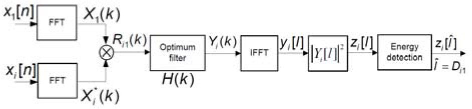
2Four-station TDOA location schemes2.1Principle of digital TDE receiverThe TDE receiver, as shown in Figure 1, is implemented by a digital cross correlator in frequency domain to detect the position of the dominant peak energy in time domain. Here we assume that receiver 1 is the reference station. When the moving target source emits the signal s[n] in three-dimensional space, the received signal of the first receiver is given by


The received signals of other three receivers are given by

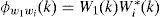
Then, the output of the cross correlation in frequency domain between station 1 and station i for i=2,3,4 is

where Di1 is the discrete time delay between receiver i and receiver 1, and
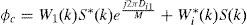
The typical TDE using cross correlation of wideband signals has been analyzed in [4], where the linear optimum filter was not included in the design.To reduce the occurrence of false peak due to the channel effect, a linear optimum filter is designed to maximize the expected signal peak relative to the output noise. The transfer function of the optimum filter is given by [5]

Where
The correlation output between receiver i and receiver 1 in time domain is determined by

Then the discrete time delay between receiver i and receiver 1 is estimated at a peak energy discrete time position Îi=Di1, i=2,3,4. The initial target location is solved by three hyperbolic equations.

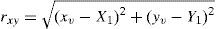
where (Xi, Yi, Zi,) and (X1, Y1, Z1,) are the coordination of the ith and the 1th receivers; (x,y,z) is the target location. ri,1 can be obtained from the measured time delay between receiver i and receiver 1.

where N is the size of the fast Fourier transform (FFT) and fs is the sampling frequency of the analog-to-digital converter. The target location in the three dimensional space is calculated by solving three hyperbolic of Eq.10. Therefore, the measured TDOA values are expressed as
2.2GNI algorithm [1][2]
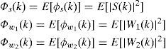
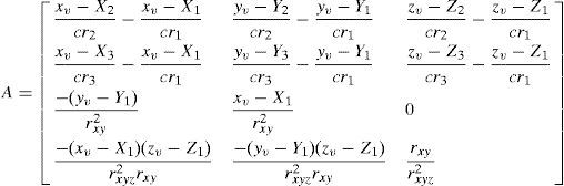
The GNI is an iteration algorithm, which uses the least square error (LSE) method to correct the initial estimated target location in the iteration until the error approaches zero. If guesses of the true initial target location (xv,yv,zv) is estimated using four-station TDOA method, by means of the first order Taylor expansion, the position equation is expressed in matrix form.

where
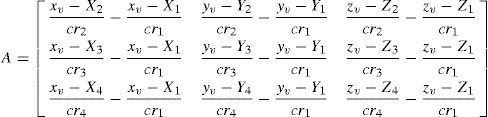
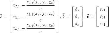
where

e→ is a measurement error vector and δ→ is an estimated position error vector in the iteration.
εi1, i=2,3,4 are identical independent distributed (IID) random variable with zero mean and covariance matrix R0 of measurement error.
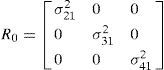
where σi12,i=2,3,4 are the variance of TDOA measurement error. Then, the correction error at each step is
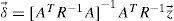
Thus, the next estimated target location is replaced wit xˆv=xv+δx,yˆv=yv+δy,zˆv=zv+δz, ŷv=yv+δy, ẑv=zv+δz.As soon as δ→ approaches to zero, the error covariance matrix becomes
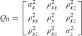
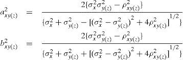
For estimating three-dimensional target position, the accuracy of the position estimation is evaluated by the circular error probability (CEP) [2][6] in xy-axis and xz-axis, which is a function of Q0. When the calculated errors are no more than 11%, the CEPs in xy-axis and xz-axis are approximated by
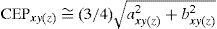
where
Therefore, the final position estimates are distributed in an error ellipsoid.
3Hybrid three-station TDOA and DOA position system3.1AlgorithmFor hybrid three-station TDOA and DOA position system, the target location can be estimated by the same procedure as the four-station TDOA position system except changing Eqs.14 and 15 as follows.
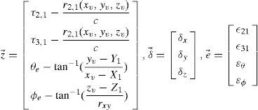
where


The DOA measurement values in horizon and elevation are defined as


By means of the first order Taylor expansion, the true DOA angles in horizon and elevation are given by [2]


σθ2 and σφ2 are the variance of measured DOA errors εθ and εϕ, respectively.
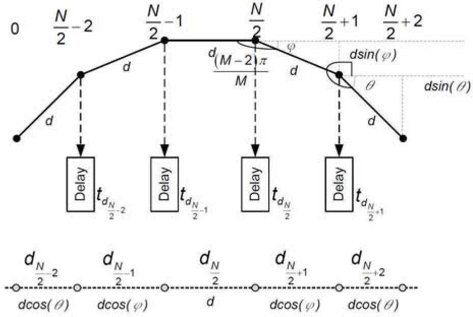
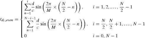
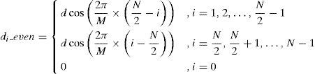
3.2Cylindrical Array AntennaA M×L cylindrical array antenna is proposed to generate three-dimensional beam pattern with equal horizontal beamwidth for hybrid three-station TDOA and DOA position system.A general formula of linear phase compensation for N-element sub-array of M-element cylindrical array antenna in horizontal plane is derived in Appendix A. When N is even, the time delay compensation for the sub-array antenna is summarized by
The separation distances among the neighbouring elements of the non-uniform linear sub-array are
To meet the requirements of the 22.5°(ideal) beam width and -20dB side lobe level in horizontal plane, a sub-array with six omni-directional elements and Chebyshev weightings In=[0.36, 0.6, 1, 1, 0.6, 0.36] is chosen to simulate the beam pattern[7].
The multimode DBF consists of a multiple beam (MB) and DOA modes. For MB mode, the output of each antenna element is subdivided into N independent signals by a (N-1)-way power divider. After the linear phase compensation, N independent signals are obtained from N adjacent elements and combined with associated weightings to generate a beam pattern of the N-element sub-array with the -20dB side lobe level in horizontal plane. The M-element array yields M beams to cover the 360° in azimuth. Each of the M beams is pointed in a fixed direction.
The amplitude comparison DOA mode [7] uses two neighbouring beams of the multi-beam antenna array with equal beam width to receive the target signal simultaneously. The signal amplitudes simultaneously received from two neighbouring beams are compared to obtain a difference signal. The measured difference signal power corresponding to the DOA of the signal from an air target is pre-stored in a look-up table of memory. The accuracy of amplitude comparison DOA mode is determined by the angular slope, which is defined as the rate of change in the power of the difference signal generated from the two neighbouring beams to the spatial angle. The more angular the slope is, the greater the accuracy of the DOA mode will be. The multi-beam antenna array is designed with the equal beam width so the amplitude comparison DOA mode can achieve the same accuracy as the DOA estimation in different directions.
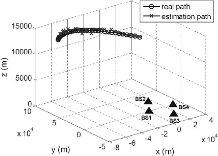
4SimulationsSimulations are performed to demonstrate the accuracy of the four-station TDOA and hybrid TDOA and DOA position systems. The 2048-point sampled orthogonal frequency division multiplexing waveform (OFDM) [8] is used to simulate target emitted signal over a two-ray Rayleigh fading channel [9]. The size of FFT is 4096 points. The TDOA measurement error is assumed to be Gaussian distributed with N (0, 10 nsec). For a 16×6 cylindrical array antenna, the horizontal antenna beamwidth is 23.4° and the elevation antenna beamwidth is 19.4°.The DOA measurement errors in horizon and elevation angles are uniformly distributed in (-11.7°, 11.7°) and (-9.7°, 9.7°), respectively. The coordinates of four stations and a three dimensional target trajectory are shown in Figure 2, where the coordinates of four stations expressed in unit of meter are station 1 (0,0,0), station 2 (15000,26000,0), station 3 (15000,-26000,0), and station 4 (30000,0,0), respectively, the initial target location is (-70000,70000,13716), the inter-distance of four stations is 30Km, the distance between the station 1 and the initial target location is 100Km. It is assumed that the target speed is 1102.6Km/hr, the stations receive the signal emitted from target once per 3Km, and the target trajectory equation is given by

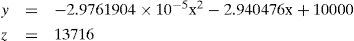
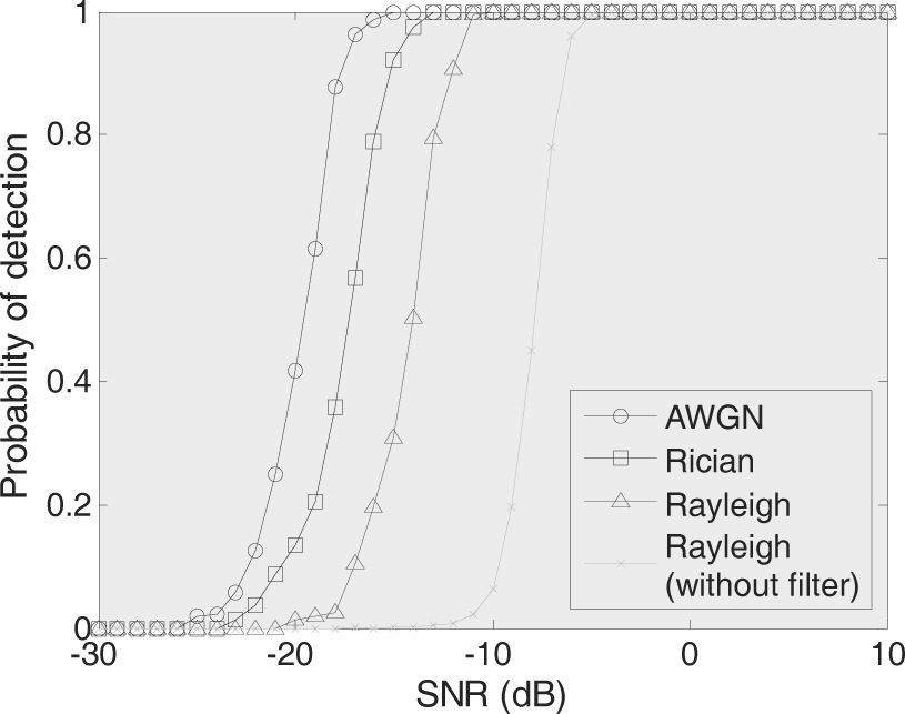
Figure 3 shows that when the SNRs of receiver with linear optimum filter are -12.7dB, -15.45dB, and -18.03dB in Rayleigh, Rician, and AWGN channels, respectively, the time delay can be successfully measured with detection probability Pd=0.9 and false alarm probability PFA=10-4. The proposed method is compared with the typical method [4] in which the linear optimum filter is not applied to TDE receiver. As shown in Figure 3, the SNR of receiver without linear optimum filter is -7dB in Rayleigh channel for Pd=0.9 and PFA=10-4.

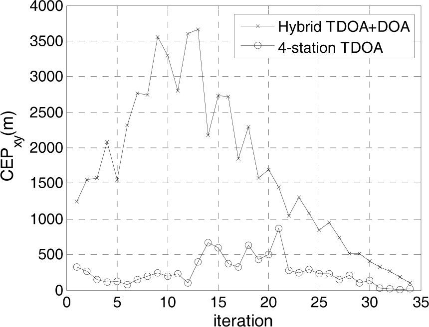
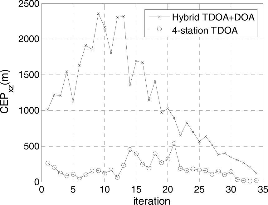
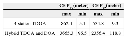
The CEPxy and CEPxz of the four-station TDOA position system and the hybrid TDOA and DOA position system operated in Rayleigh fading channel are shown in Figures 4 and 5 for SNR=-12.7dB, respectively. The minimum and maximum CEP values are listed in Table 1, which demonstrates that the accuracy of the four-station TDOA position system is better than the hybrid TDOA and DOA position system.
5Conclusions

In this paper, the digital TDE receiver is designed for TDOA measurements and a cylindrical array antenna is designed for DOA measurement. The OFDM signal is used to test the position accuracy over Rayleigh fading channel. When the SNR of the digital TDE receiver is -12.7dB, the TDOA can be successfully measured with detection probability of 0.9 and false alarm probability of 10-4. The proposed TDE receiver get 5.7dB gain compared with typical TDE receiver [4] without using linear optimum filter. The accuracy of the four-station TDOA position system is superior to the hybrid TDOA and DOA position system. But the location function of the position system is still available when the received signal of any one of four stations cannot be sent to the reference station. Simulations find out that the proposed three-dimensional position architecture can provide accurate and reliable target location function.
AcknowledgementsThe research work was supported by the research grants from National Science Council, Taiwan, R. O. C. (NSC 99-2221-E-155 -031) and CSIST.
Derivation of Eqs (31) and (32) of linear phase compensation for cylindrical array antenna in horizontal plane
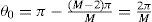
The M elements of the cylindrical array antenna in horizontal plane are placed at the vertexes of a polygon of M sides. The separation distance between the elements is d and each internal angle is (M-2)π/M. Power dividers are used to generate N branches of the output signal from each sub-array element. Each signal can be individually combined with N-1 other signals of adjacent elements to generate a beam. When N is even, for the right half part of sub-array antenna, as shown in Figure A1, the angle θ0 of the (N/2)th array element with reference to horizontal axis is derived as

The angle θ1 of the (N/2+1)th array element with reference to horizontal axis is derived as
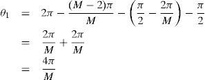
Therefore, the angle θi of the (N/2+i)th array element is 2πi/M.
The separation distances among the neighboring elements for the right part sub-array are expressed as

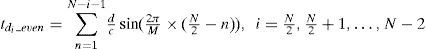
The time delay compensation for the right part subarray is given by
For the left part sub-array, the angle of the (N/2-1)th array element with reference to horizontal axis is (2π/M)×1, and the (N/2-2)th array element with reference to horizontal axis is (2π/M)×2. The separation distances among the neighboring elements of the non-uniform linear array are

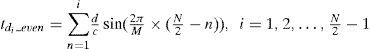
The time delay compensation for the left part subarray is given by
Eq. 31 is in terms of Eqs. A4 and A6 and Eq. 32 is in terms of Eqs. A3 and A5.