


Bone is a heterogeneous material in which structural levels can be identified, from the microscale to macroscale. Multiscale models enable to model the material using homogenization techniques. In this work, an innovative homogenization technique for trabecular bone tissue is proposed. The technique combines the fabric tensor concept and a bone phenomenological material law, linking the apparent density with the trabecular bone mechanical properties. The proposed methodology efficiently homogenizes the trabecular bone highly heterogeneous medium, allowing to define its homogenized microscale mechanical properties and to reduce the analysis computational cost (when compared with classical homogenization techniques). In order to verify the efficiency of the technique several examples were solved using a confined square patch of trabecular bone under compression. In the end, the results obtained with a classic homogenization technique and the proposed methodology were compared.
Bone biomechanics, one of the main biomechanics field of study, is based on the idea that load bearing bone tissues are structurally optimized for their mechanical function [1,2]. It is normal to classify bone as a hierarchical structure, where the different structural levels that can be identified as belonging to macroscale or a microscale level [3]. The entire bone (macroscale) and the trabecular architecture level (microscale), can be defined by different physical properties due to its different functional requirements. At the trabecular level, microscale, is possible to recognize the bone trabecular non-homogeneous structure, which after being homogenized allows to define local anisotropic homogeneous mechanical properties, such as apparent density and directional Young moduli.
Bone is a tissue that renews itself by a biological process called bone remodelling [4]. This bone remodelling is progressive and induces adaptation of bone morphology to any new external stimulus. Wolff in 1886 reported the concept that strain/stress induces bone remodelling [5]. Thus, Wolff reported that the orientation of trabecular bone coincides with the direction of the stress trajectories, proposing that external loads were, somehow, sensed by the bone. This principle is known as Wolff's law. In 1939 Wolff's law was firstly described in vitro by Glucksmann in 1939 [6] and was described mathematically in 1965 by Pauwels [7]. Later, this formulation was computationally implemented by Pettermann et al. [8]. In their bone remodelling algorithms, many authors have considered bone as an isotropic material, a simplistic approach on the behaviour of trabecular bone, disregarding the importance of orientation in the remodelling process [9–12].
Meanwhile other models where created linking material density and orientation with its anisotropic mechanical properties, allowing to overcome the material isotropy simplification. These remodelling models not only avoid any a priori assumption on material but also take into account the trabecular architecture [13–16]. More recent models start to consider biological and mechanical factors based on bone cell activity, resulting in mechanobiological models, which allow to simulate the evolution of bone tissue considering both mechanical and biological stimuli [17–20].
Bone started to be characterized mechanically using the fabric tensor concept [21,22]. Fabric tensor is a symmetric second rank tensor that characterizes the arrangement of a multiphase material, encoding the orientation and anisotropy of the material. Back in 1985, Cowin [23] developed a relation between the elasticity tensor ℂijkl and a fabric tensor A, proving that an ellipsoid may be associated with the varieties of material symmetries observed in many natural materials. The fabric tensor can be acquired by two different techniques, the mechanical based techniques and by the morphologic-based. In morphologic-based methods the interface between phases of the material are to estimate the fabric tensor. The bone morphology is usually obtained using a micro-CT (at the microscale) or a CT (at the macroscale). Most of the available techniques, using morphologic-based methods, obtain the fabric tensor applying an orientation distribution function (ODF), which is estimated from an orientation-dependent feature of interest.
In mechanics, and in biomechanics, the accurate determination/characterization of the material's mechanical properties is a key parameter, which will allow to describe and predict numerically the behaviour of such materials for different scenarios.
Discrete numerical methods allow to study and analyze in silico the behaviour of materials and structures, being the finite element method (FEM) one of the most popular discrete numerical method [24].
2Homogenization techniqueIn this section, the used homogenization technique is fully described. Firstly, 2D images (thin slices) were selected. The images correspond to the cuboid bone and describe locally the bone morphology at its microscale. Then, it was applied the fabric tensor concept in order to determine the material orientation to the selected square microscale images. Additionally, a bone tissue phenomenological law was used to obtain the homogenized material properties of the microscale patch. This homogenization allowed to define the anisotropic mechanical properties of the trabecular bone. Fig. 1 represents the algorithm describing the proposed homogenization technique.
2.1Fabric tensor morphologic based method
By defining a relevant micro-CT slice image and then identifying a square region of interest with relevant information (the binary image represented in the left-upper image of Fig. 1), it was possible to define the morphologic based fabric tensor. This square patch, a grey scale image, was then binarized, resulting in a binary image Is that contained the characteristic morphology of the (local) trabecular bone.
To define the fabric tensor it was used a methodology developed by Whitehouse [25], in which the number of interceptions between a parallel family line set, with direction ι, with the interface between both phases of the material was counted, Int(ι). The length of the parallel lines family, h, for the ι direction was also obtained. Knowing h and ι, it was possible to define the ODF, which in this case is called mean intercept length (MIL), represented in Eq. (1):

Whitehouse's methodology is considered a golden standard to predict mechanical properties of trabecular bone since exists a large amount of works that sustain its appropriateness [25–29]. The literature shows that when the ODF data is disposed on a polar plot and fitted in an ellipse, the corresponding ellipse parameters can be correlated with the material orientation (its anisotropy), in particular the trabecular bone [30].
The dimensional information of Is was used to define the size of an image containing the family of parallel lines with ι=0°. Counting the interceptions of those parallel lines with the boundaries of the binary image square patch, it was possible to obtain the orientation-dependent feature.
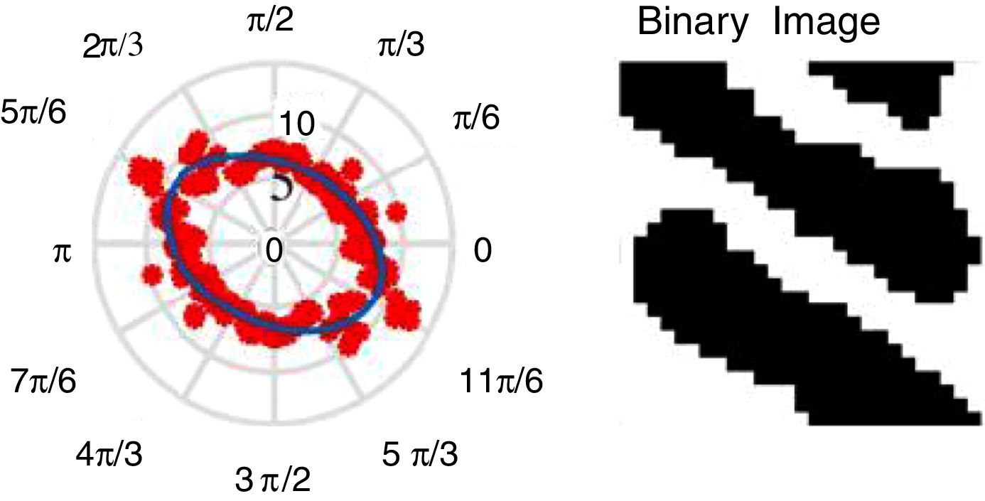
Rotating the family of parallel lines image with ι between 0°and 180°, and then counting the interception of the family of parallel lines with the square patch binary image Is, was possible to obtain the ODF of the Is. The created data for ι between ]180°, 360°] is a ]0°, 180°] data repetition, since the orientation-dependent feature depends only on the orientation and it is not influenced by the direction. The created ODF data was then plotted in polar coordinates, where was fitted an ellipse, from which it was possible to obtain the material orientation of the trabecular micropatch (see both central boxes of Fig. 1). From the fitted ellipse were extracted the ellipse minor axis length, βmin, the major axis length, βmax and the θ, the angle of ellipse major axis with the polar plot horizontal axis, parameters.
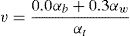
2.2Phenomenological material law methodUsing fitted ellipse information and the average apparent density of the binary image Is it is possible to define the homogenized anisotropic mechanical properties of Is. Thus, first it is necessary to define the average apparent density, ρapp, of the binary image Is. As Eq. (2) shows, the apparent density, ρapp, can be obtained using the number of white pixels, αw and black pixels, αb, of Is. In this work, the cortical bone apparent density assumed as ρappcortical=2.1 g/cm3

Using the ρapp and the phenomenological material law [31], the axial Young's modulus Eaxial can be defined.
If ρapp≤1.3, it should be applied Eq. (3), otherwise, it should be used Eq. (4)[31]. Coefficients aj and bj can be found in Table 1


Coefficients for the assumed phenomenological material law [31].
| j=0 | j=1 | j=2 | j=3 | |
|---|---|---|---|---|
| aj | 0.0E+00 | 7.216E+02 | 8.059E+02 | 0.0E+00 |
| bj | −1.770E+05 | 3.861E+05 | −2.798E+05 | 6.836E+04 |
The transverse elastic modulus Etransc was defined using the relation between the ellipse minor axis length, βmin, and major axis length, βmax, and the axial elastic modulus Eaxial as Eq. (5) shows:

The Poisson's coefficient, v, was calculated according the mixture theory using the relation between white and black pixels, as represented in Eq. (6), being αt the total number of pixels of the binary image Is:
The shear modulus, G, was expeditiously calculated using Eq. (7):

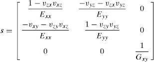
As Fig. 1 shows, using the homogenized material properties (Eaxial, Etransv, v and G) the constitutive matrix is defined cox′y′ for the ox′y′ local coordinate system (oriented with the material principal axis, following the material principal directions ‘axial’ and ‘transverse’). To define this matrix to the global axis, is used the angle θ obtained from the ellipse fitting, and so is used a transformation rotation matrix T, Eq. (8), being possible to define the material constitutive matrix in the global axis, coxy, Eq. (9), defined with c=s−1. The anisotropic compliance matrix s is defined by Eq. (10):
3Numerical examples

To validate the homogenization methodology were performed some numerical tests involving size and rotation analyses of predefined Is binary images.
Thus, to confirm the robustness of the proposed technique, a benchmark binary image (with a known preferential material orientation) was analyzed. Then, the input image was rotated and it was verified if the fitted ellipse (from the fabric tensor based methodology), was aligned with the material orientation of the image.
Furthermore, in order to verify the behaviour of the proposed homogenization technique, it was performed a structural FEM analysis using two distinct geometrical models (a homogeneous model and a heterogeneous model).
3.1Validation of MIL methodologyThe validation of the MIL methodology will be assessed with two distinct studies. The first study will verify the influence of the size of the representative volume element (RVE) in the determination of the anisotropic constitutive matrix. In the second study, the consistency of the methodology will be tested, by imposing known material orientations to the model.
3.2RVE sizeIn order to understand the influence of the size of the RVE in the proposed methodology, two distinct models were constructed, Fig. 2(a) and (b). The model presented in Fig. 2(a) is a benchmark fabricated unitary binary image showing a well-defined material orientation (90°). This model was repeated rn×rn being rn the number of repetitions of the RVE. For illustration purposes, Fig. 2(c) represents a 10×10 repetition.
 Benchmark fabricated unitary image. (b) Realistic binary image from a micro-CT. To analyze the effect of using different RVE sizes, the binary images were repeated up to a 10×10 repetitions. (c) 10×10 repetitions of benchmark fabricated unitary image and (d) 10×10 repetitions realistic binary image.")
Binary images used to verify the MIL dependence on the RVE size. (a) Benchmark fabricated unitary image. (b) Realistic binary image from a micro-CT. To analyze the effect of using different RVE sizes, the binary images were repeated up to a 10×10 repetitions. (c) 10×10 repetitions of benchmark fabricated unitary image and (d) 10×10 repetitions realistic binary image.
Alternatively, the model shown in Fig. 2(b) is a unitary binary image representing a realistic trabecular square patch obtained from a micro-CT image. Similarly to the benchmark fabricated unitary binary image, this patch was repeated rn×rn, being the 10×10 repetition shown in Fig. 2(d).
The propose homogenization methodology was applied to each one of the RVEs (fabricated benchmark and realistic square patch) and their several corresponding repetitions rn×rn, being rn={1, 2, 3, …, 10}.
Following the described homogenization methodology it was possible to obtain all the components of the constitutive tensor coxy′ as can be seen in Fig. 3(a), for the fabricated benchmark RVE, and in Fig. 3(b) for the realistic trabecular RVE. In both figures, it is possible to visualize the evolution of the components of the constitutive matrix, Cij, with respect to the number of repetitions of the corresponding basic unit RVE. For both RVEs types (benchmark and realistic), it is perceptible that the value of each component of the constitutive matrix, Cij, do not vary significantly with the number of repetitions, rn.
 Results for the trabecular square patch obtained using the micro-CT image. (b) Results for the created image.")
Notice that for the fabricated benchmark RVE, as expected, θ does not suffer any significant variation (the average value is 45° with a standard deviation of 0°). Similar, for the realistic trabecular RVE the number of repetitions do not relevantly change the material orientation angle of the basic unit RVE being the obtained average value: 115.7° with a standard deviation of 1.0°.
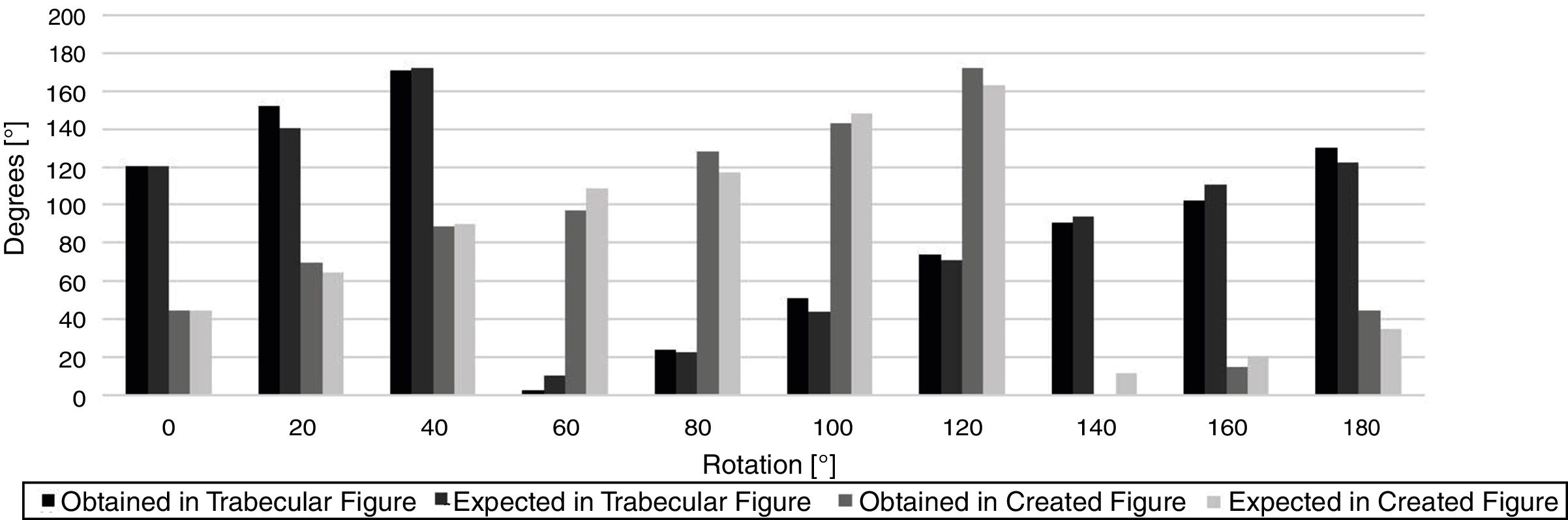
3.3RVE rotationTo verify if the developed methodology is capable to deliver accurate material orientations, both, the benchmark fabricated RVE, Fig. 2(a), and the realistic trabecular RVE, Fig. 2(b) were rotated. The RVEs were rotated in relation to their initial position following increment angles of 20° between the interval [0°,180°]. Figs. 4 and 5 show the results of a single analysis for the exposed case. It is possible to visualize the orientation/size of the produced ellipse and the corresponding angle of the material. In Fig. 6 are represented the material orientation angles θ of the fitted ellipse, and the expected ones for a 20° rotation. The difference between the expected orientation and the obtained material orientation θ (coming from the proposed MIL algorithm) can be explained by the change of the source image upon the rotation process, performed using a MATLAB 2016b function. This leads to the change of the number of white pixels of the image, a parameter highly related with the calculation of the fabric tensor.
4Structural application


In this section is verified if a homogenized RVE, with homogenized anisotropic mechanical properties obtained with proposed methodology, is capable to produce a homogenize von Mises effective stress field similar with the one obtained with a heterogeneous RVE.
To evaluate the efficiency of the proposed homogenization technique, it is performed a structural analysis of the realistic trabecular RVE, Fig. 2(b), and its rn×rn repetitions, and the results are compared with the ones obtained with a homogeneous RVE.
The same essential and natural boundary conditions were applied to all the RVEs. Being all the RVEs squares micro patches with dimensions L×L, it was imposed a displacement of 0.1×L at the nodes of the top layer, y=L. The nodes at x=0 and x=L where constrained on Ox direction, u=0, and the nodes at y=0 and y=L where constrained on Ox and Oy direction and, u=0 and v=0. This constrains are exemplified in Fig. 7.

The homogeneous RVE is typically discretized by a set of n×n nodes uniformly distributed within the RVE domain, Fig. 8(a). All the integration points of the homogeneous RVEs models possess the same homogenized material properties, while the heterogeneous RVEs (the realistic trabecular RVE) is formed by trabecular bone and void space, the discretization of such complex domain is exemplified in Fig. 8(b).
 Discretized homogeneous RVE. (b) Example of a discretized heterogeneous RVE created using micro-CT image information.")
Applying the proposed homogenization technique to the RVE it is possible to obtain the anisotropic material properties presented Table 2, column “Homogeneous RVE”. Thus, every integration point of the homogeneous RVEs will assume these materials properties.
Since the realistic trabecular RVEs are binary images, containing bone or void space, it is necessary to assume mechanical properties for these two materials, as indicated in Table 2, trabecular bone and void space.
The mechanical properties of the trabecular bone were defined as isotropic according to the literature [32].
Since the geometrical information coming from the micro-CT forces the existence of the void space in between the trabeculae, it was necessary to define this ‘material’ as solid, hence, the material was defined as a soft material that would not (significantly) interfere with the global structural response of the RVE, being attributed a Young's modulus with a much lower magnitude when compared with the trabecular bone.
Two homogeneous RVEs were analyzed, one with 11×11 nodes and another with 21×21 nodes. The von Mises effective stress maps obtained with FEM, presented in Fig. 9(a) and (b).
 1×1 and (b) 2×2, and for heterogeneous model, (c) 1×1 and (d) 2×2.")
In order to compare the stress field obtained with the homogeneous RVE with the heterogeneous RVE, the concept of homogenized stress is used.
The RVE's von Mises effective stress field (or any other RVE's stress/strain field) can be summarized in one scalar value, the homogenized von Mises effective stress, which can be defined with Eq. (8), being nQ the number of integration points discretizing the problem domain and not belonging to the vicinity of the domain boundary:

In Fig. 10 blue dots represent the integration points that will be included to calculate σeffh and in red the integration points that will be excluded from Eq. (11).

This homogenization excludes only 2% of the integration points forming the integration mesh. This exclusion is necessary to avoid the (inaccurate) stress concentrations that appear near the domain boundary, as can be seen in Fig. 9.
Thus, Fig. 11 shows the homogenized von Mises effective stress, σeffh obtained for each analyzed RVE, using FEM. In the figure, besides the homogenized von Mises effective stress determined in the integration points, it is also shown the σeffh obtained at the nodes. The stress at the nodes is obtained by linear extrapolation using the element information.

Notice that four heterogeneous RVE were considered: a 1×1 heterogeneous RVE (corresponding to the one represented in Fig. 9(c)), a 2×2 heterogeneous RVE (corresponding to the one represented in Fig. 9(d)), a 3×3 and a 4×4 heterogeneous RVEs following the same repetition rule.
It is visible in Fig. 11 that increasing the level of detail and the size of the heterogeneous RVE, which are governed by the number of repetitions (the 1×1 RVE has a lower detail than the 4×4 RVE), the value of the homogenized stress decreases. Thus, when the analysis uses a heterogeneous model following a 4×4 repetition, the obtained homogenized stress is very close with the homogenized stress obtained with the homogeneous RVE.
This indicates that the homogenization technique proposed in this work is capable to accurately obtain the homogenized anisotropic material properties of a trabecular patch. Each one the analyses has its own computational cost. In Fig. 12 are shown the time-lapse of each structural analysis. Observing the computational cost of each analysis, it is possible to understand that the analysis of the homogenized RVE is much faster than heterogeneous RVEs (with rn×rn, rn={1, 2, 3, 4}). In Fig. 11 it was shown that the 4×4 heterogeneous RVE produces results very close with the homogeneous RVE. However, the 4×4 heterogeneous RVE takes 5000s to analyze and the homogeneous RVE only requires 4–6s.
 of each analysis.")
Generally, the multiscale techniques use highly discretized RVEs, with a high computational cost associated. As this example shows, the proposed homogenization methodology is capable to reduce the cost of the multiscale analysis, enabling more demanding simulations.
5ConclusionsThe methodology introduced in this work allows to define the mechanical properties of a micro-CT trabecular bone square patch without any a priori knowledge. The obtained data using sing the MIL methodology, enables to define the material orientation using a distribution function. This function is approximated by a ellipse function, as described by Moreno et al. [30], can define a tensor (a 2×2 matrix) that represents the bone trabeculae distribution/density. With this, it is possible to define the material mechanical properties, directly related with the trabeculae anisotropy encoded in the fabric tensor and with a phenomenological material law [31]. The studies performed to evaluate the behaviour of the methodology (both RVE scale and rotation studies), revealed that this methodologies are stable and provide good results.
In this work, it was verified that with the homogeneous RVE (whose material properties were obtained using the proposed homogenization technique) it is possible to produce similar results with the ones obtained with highly heterogeneous RVE (the heterogeneous RVE).
Nevertheless, it was shown that an elasto-static analysis using the homogeneous RVE only takes 4–6s to perform and the same analysis with the 4×4 heterogeneous RVE takes about 5000s, 1000× more.
Since usually multiscale techniques use highly discretized RVEs, it is expected that the homogenization technique here proposed will be capable to reduce the cost of the multiscale analyses, allowing to simulate more complex problems.
The authors truly acknowledge the funding provided by Ministério da Ciência, Tecnologia e Ensino Superior – Fundação para a Ciência e a Tecnologia (Portugal), under Grants SFRH/BD/110047/2015 and SFRH/BPD/111020/2015, and by project funding UID/EMS/50022/2013. Additionally, the authors gratefully acknowledge the funding of Project NORTE-01-0145-FEDER-000022 – SciTech – Science and Technology for Competitive and Sustainable Industries, cofinanced by Programa Operacional Regional do Norte (NORTE2020), through Fundo Europeu de Desenvolvimento Regional (FEDER).
