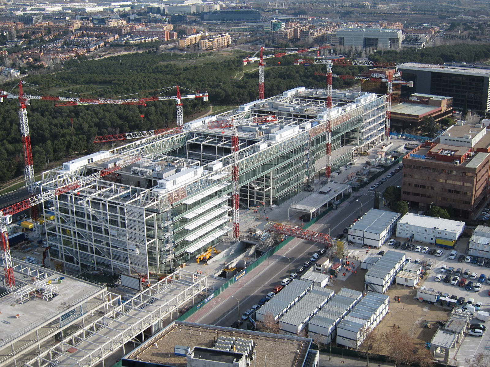
The construction of the Banco Popular new headquarters has been developed in two phases. In the first phase, the new Data Processing Centrebuilding was designed and built next to A-2 motorway in Madrid, and came into use in January 2013. The second phase of the building's structureis now finished and it is planned to be fully completed in June 2017. This second phase, with a constructed area of 125,000 m2, incorporates a greatvariety of structural solutions into a unique architectural project of great representative value. The article will focus mainly on this second phase.
La construcción de la nueva sede del Banco Popular en Madrid se ha desarrollado en dos fases. Una primera en la que se proyectó y construyó el nuevo edificio para el Centro de Proceso de Datos, junto a la autopista A-2 en Madrid, entrando en uso en enero de 2013. La segunda faseactualmente tiene ejecutada la totalidad de la estructura y está prevista su finalización completa en junio de 2017. Esta segunda fase, con unasuperficie construida de 125.000 m2, incorpora una gran variedad de soluciones estructurales a un proyecto arquitectónico singular y de gran valorrepresentativo. El artículo se centra fundamentalmente en la descripción de esta segunda fase.
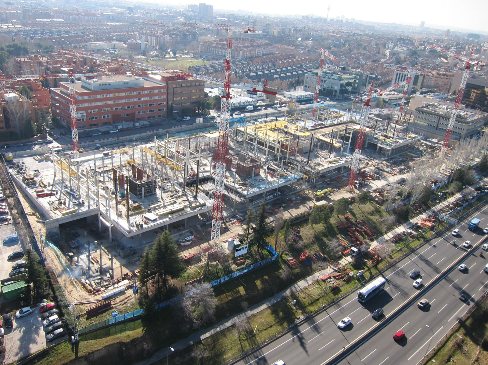
During the month of October 2008, Banco Popular launched a call for tender for its new headquarters in Madrid to be developed on two separate plots, both located on either side of the A-2 motorway as it leaves Madrid. The first plot, located at calle Abelias, on the northern edge of the motorway, would house, in a single building, the new Data Processing Centre (CPD) of the bank and offices. The second stage would be developed on the plot resulting from joining the plot on which Banco Popular's old CPD building was located, on the southern edge of the motorway, to the neighbouring plot, recently acquired by the bank, where the old printing press workshops of the ABC newspaper were located, at calle Luca de Tena (Fig. 1).
The Banco Popular's former CPD building (Fig. 2, 1981), project of the architect Eleuterio Población, (designer of, among others, the “Beatriz” building (1968), headquarters of Banco Popular since 1976, located at calle Ortega y Gasset in Madrid), was demolished prior to commencing the construction works, as were the printing press workshops of the neighbouring newspaper ABC.
Of the seven teams bidding for the tender, the winning team is managed by the Madrid studio Arquitectos Ayala, which MC2 Estudio de Ingeniería forms part of for the development of the structures project and the subsequent technical structural assistance to the construction management.
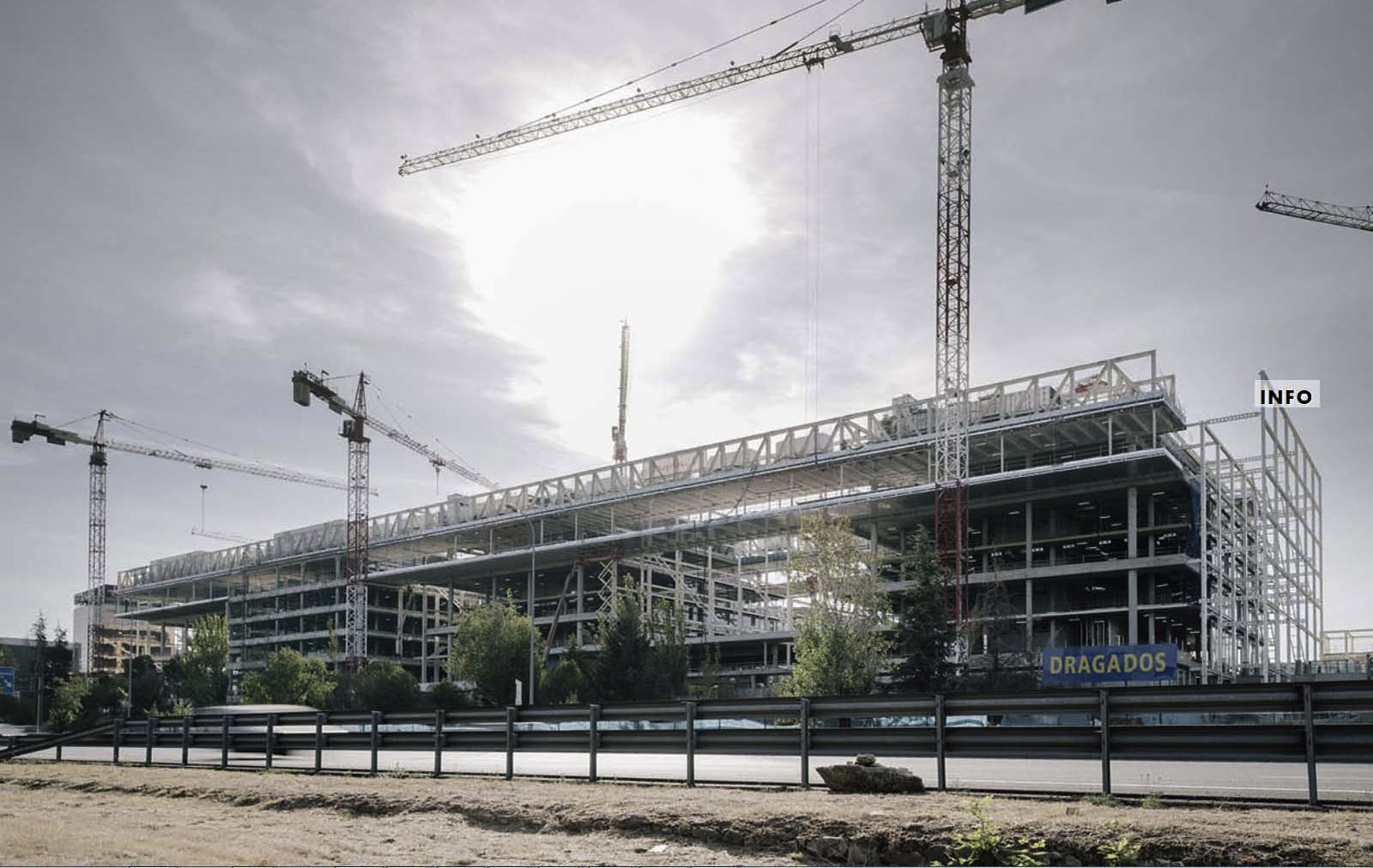
The execution of the first stage (Fig. 3) took place between January 2010 and December 2012 [1] and continued simultaneously alongside the development of the second stage of the project. During the summer of 2013 the first retaining walls were built on the stage 2 plot, with the main elements of the structure being completed in September 2015. The completion of the works and commissioning of the building will take place in June 2017.
New Data Processing Centre building at calle Abelias (stage I) [4].
An important characteristic of the development of the project, which determines the designs of the architectural and structural solutions, is the smooth teamwork between the architectural and structural teams from the beginning of the project right up until the finishing touches. On the basis of the architectural concept selected by the owners, the teams collaborate to produce specific designs that integrate architectural, functional and structural requirements.
2.1Architectural concept, basis for the design of the buildingThe plot is rectangular in shape with its longest side measuring around 315m in length running parallel to the A-2 motorway. The perpendicular spread is around 96m, which are staggered along the north-west border adjacent to the current building of the editorial department, and headquarters of the ABC newspaper, to the west of the plot (Fig. 4).
The layout of the headquarters is thus formed within a large rectangular of builds, which is divided into four units or blocks (A–D) that hold the main body of the space dedicated to offices. To the far west there is a building with an unusual layout where the various services for the development and public access services will be housed: shopping centre, branches, etc. (Fig. 5).
Between the blocks there are patios that allow natural light to fall on almost the entire floor surface of the levels, with each of the blocks having a communications core with stairwells and lifts.
Block C stretches towards the A-2 motorway, whilst block A leans off towards the West, increasing the space between the blocks until a large entrance square is formed where visitors and employees are received, embracing them in surroundings protected by the transparent façades of the blocks to the sides, a juxtaposition of descending levels on the floor plan and the conference hall area at the front, also covered by transparent glass (Fig. 6).
The blocks have five levels above ground level at calle Luca de Tena, the fourth floor houses the presidential area which, like the fifth floor roof level, is extended by connecting the four blocks at their façades (Fig. 7). This way large cantilevers and “bridges” are created between the blocks on the fourth and fifth levels, whose structural composition must also implement the support structures for the machines and noise-reduction panels on the roof.
The types of units designed for the roof are:
- •
Between blocks A and B “bridges” are needed to connect both the north and south façades. The distance between supports is 46.80m.
- •
The fourth and fifth floors protrude outwards towards the A-2 motorway with a 7.80m span cantilever, with the exception of block C which, due to being set back, forms its projections in a southerly direction.
- •
The remaining blocks are connected to each other through shorter bridges, with distances between supports of 9.50m.
The geometry of each of the blocks is built on the basis of units measuring 7.80m in a north-south direction, which determines the grid for the columns. In an east-west direction, the first span closest to the core measures 10.40m, whereas the second span is 6.50m (Fig. 8). However, this last line of supports is located outside the façade, so that there must be a structural connection element crossing the façade. The exterior columns are steel profiles and also serve as supports for the exterior steel structure of the fire escape.
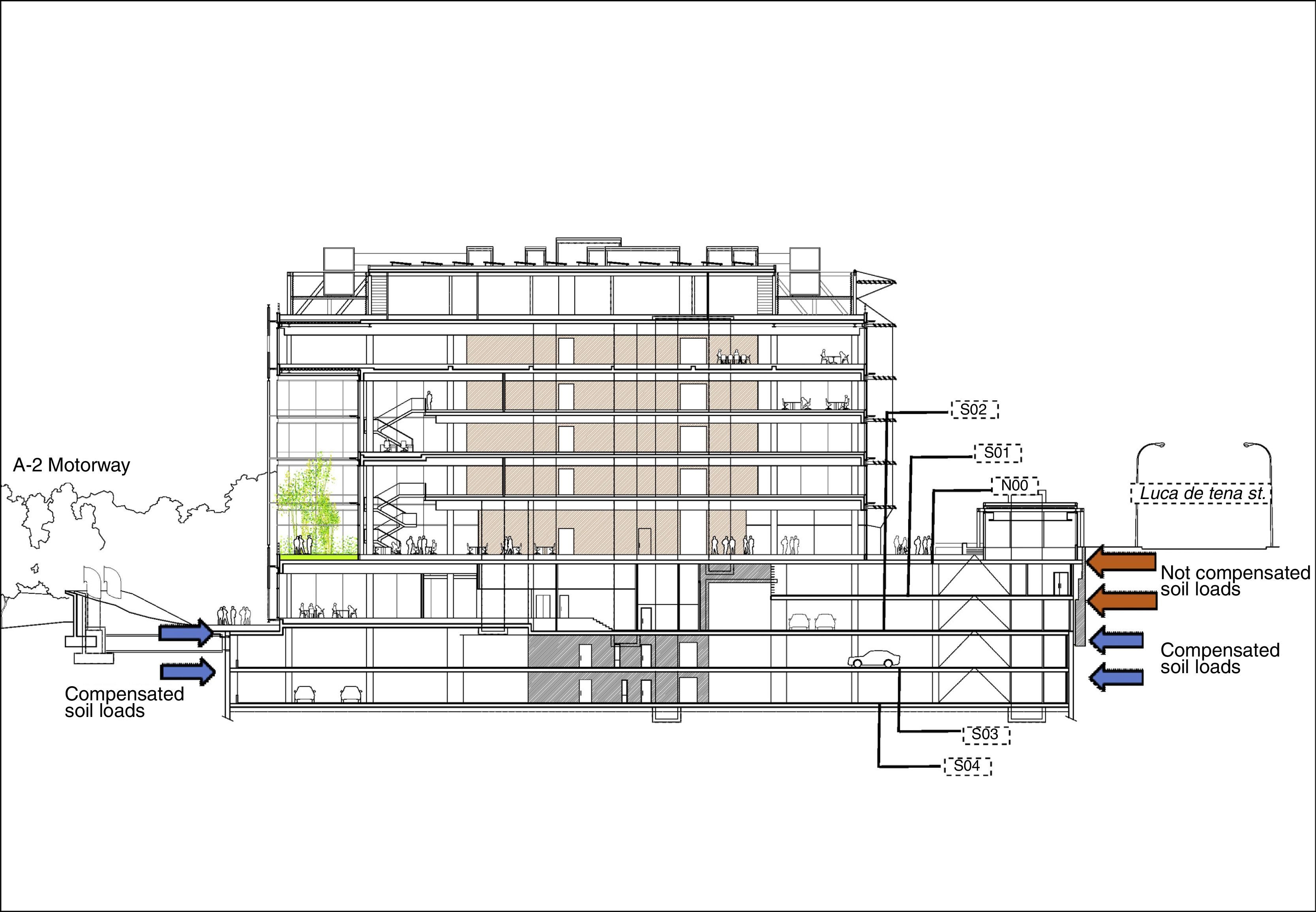
Below ground level of the calle Luca de Tena there are four basement levels that occupy the entire plot. Floor S01 extends partially towards the core of the blocks, whereas floor S02 extends from Luca de Tena to the opposite edge of the plot, on the A-2 motorway border line which reaches the ground level of the natural land. It can be said, therefore, that there are two (and not four, like in Luca de Tena) underground levels on the A-2 motorway side.
2.2Summary of architectural parameters with the greatest influence on the structureThe architectural planning of the ensemble, the geometric conditions of the surroundings and the functional requirements define the parameters that condition the development of the structure. The main ones are:
- •
Retaining walls that must integrate part of the existing walls of the former buildings.
- •
Soil pressure load compensation (two levels) between calle Luca de Tena and the A-2 motorway.
- •
Total length of continuous underground framework of around 300m.
- •
The architectural unit for the offices above ground level must be adapted to the requirements imposed by the squares and underground parking rows. This requires to bear the loads of the columns that descend from the office areas on beams, which are also conditioned by strict gauges. For the same reason, parts of the concrete walls of the communications core are hold up in the same way.
- •
The conference hall area reveals some unique elements, such as a cantilever grandstand with an exposed flat bottom face and a span length of 9.60m, and thin columns for the roof.
- •
Important roof structure, with span lengths of close to 50m and a 7.8m cantilever length resting on columns that drive loads of up to 37,000kN down to the foundations.
- •
Exterior steel structure holding the fire escape and perimetral columns for the blocks. Columns must be coordinated through the façade.
As regards the roof structure, the determining factors are:
- •
The fourth floor must be as open plan as possible and close to the layout of vertical elements located underneath it (Fig. 9). That is why the main body of the structure must be above the roof slabs. The fourth floor hangs by way of ties that follow the geometric unit of the columns, leaving the floor as equally transitable as the remaining office floors. It is thus recommended to reduce the weight of the floor to optimise the structure.
- •
On the roof, the building's main installations are housed, with generator sets, coolers, etc. as well as the formation of the roof itself (weather-proofing, sound-proofing, sloping, etc.). The structure must therefore foresee the loads and placement of these machines and the layout of the conduits.
- •
The intersection between cantilevers and “bridges” means the latter require one of the supports at each end the end that takes the weight of the cantilever, to be more flexible than the one that is directly supported by a column. This means having to compensate for related movements by adjusting the cambers during the manufacture of the structure.
- •
The columns receive different loads depending on whether they hold cantilevers, bridges or both at the same time. In the first case, the reference design load for each column is 14,000kN, in the second it is 10,000kN, whereas when the column receives loads from a big bridge and a cantilever, this is 27,000kN (design value).
- •
By being located on the roof, the structure is outside the building cladding, and thus subject to thermal changes of the external environment.
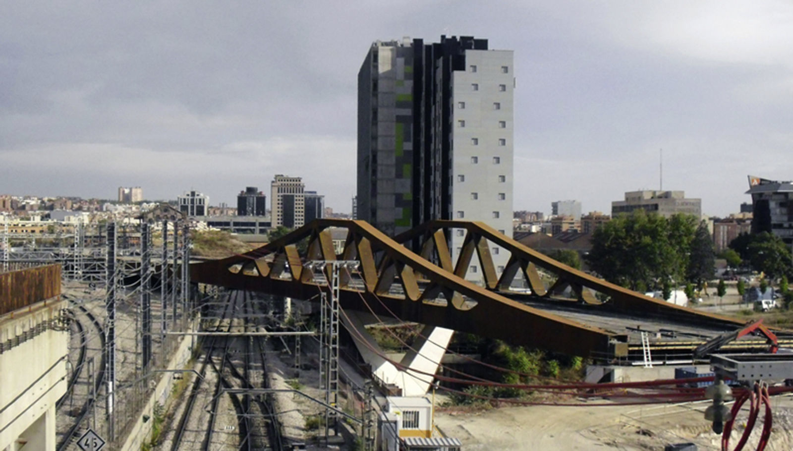
To a certain extent, the roof structure follows the general roof plan designed for the Data Processing Centre building (CPD) (Fig. 10) [1], although on a larger scale both in terms of bridge spans (26m compared to 50m) and in total length. In this second stage the roof trusses are designed to be exposed, and thus exposed to the sun, unlike the stage I of the execution design of the CPD, where they were hidden by the cladding.
Some architectural references that could be cited regarding unique buildings with a similar structural design (large spans or bridges to resolve with steel or composite trusses) include the Gas Natural headquarters building in Barcelona (Fig. 10), the Teatros del Canal in Madrid [2], etc.
3Structural solutions3.1Retaining walls3.1.1General overviewThe retaining wall measures 810m in length, with excavations of between 15.20m (calle Luca de Tena side) and 7.90m in depth (A-2 side).
The plot shows stable water levels at very different depths according to the boreholes. Thus, in the east area of the perimeter on calle Luca de Tena there were levels of 4.00m below ground level, whereas to the extreme west of the plot the phreatic levels were always located under the foundation level of the building. The significant technical and financial repercussions that the hydrostatic pressure has on the design lead to additional works being studied:
- •
Stabilisation of the levels, to study possible variations due to recharge in the rainy season. To that end measurements were taken in boreholes over the course of a little over the full previous year, and throughout the execution phase.
- •
Study of the filtration volumes under the retaining walls to dimension the drainage network (Fig. 11).
Figure 11.Finite element analysis of (ANSYS®) of the filtration volume beneath the retaining walls. Dimensioning study of the depth of embedding the retaining walls, dimensioning of the drainage network and subsequent up-lift loads on neighbouring foundation elements (drainage wells, septic tanks, footings, etc.). Pressure contours (above left [m]), filtration volume (below left [m3/s]) stream lines (right) of a retaining wall cross-section, calle Luca de Tena.
(0.64MB). - •
The borehole network was increased to obtain additional measurements at intermediate points along the perimeter, the control of which was maintained during the execution and auscultation phase of the retaining walls, and control drainage tubes were placed in foundation trenches along the border with calle Luca de Tena and the A-2 motorway, with at least two tubes per trench at different heights to control the phreatic level.
Based on the previous results, the technical and financial comparative study between secant piles and continuous retaining walls, which compared the different distributions of the anchors and thicknesses of the wall, concluded that the most favourable solution was continuous reinforced concrete retaining walls measuring 0.45 and 0.60m in thickness, executed through trenches of up to 3.00m. The wall was supported with temporary injected anchors. In the area with greatest height and hydrostatic pressure, three levels were created with anchors of up to 600kN, reduced to a single file of anchors of 300kN for the sections of the wall that least needed them, at a lower height and without hydrostatic pressure.
3.1.2Interaction with existing wallsOn the calle Luca de Tena border, each of the sections of the wall that supported the road during the demolition of the ABC printing press warehouse were protected by a verge of provisional backfill, measuring an average of 7.50m from ground level to the upper part of the foundations.
The pre-existing on-site study that was carried out, as there was no documentation for those retaining walls, defined the structure as:
- •
A 94m long section of reinforced concrete wall, with a thickness that decreases with height from 1.00m to 0.30m, which, due to its size and that of its foundations, could have been designed as a cantilever to support the street. The extracted concrete pass-through test cylinders showed how, in effect, the wall had shuttering on both sides. Also a minimum available amount of reinforcement was established for analysis and the depth of the foundation footings was characterised.
- •
A second section of the brickwork wall, measuring 10m in length, built as a continuation of the concrete wall, but slightly set back towards the inside of the plot. The brickwork section of the wall was the same height as the concrete wall (around 7.50m).
Taking into account that they should not affect the calle Luca de Tena, the following solutions were proposed:
- •
Existing reinforced concrete wall. As the excavation progressed, anchors would be placed in the body of the wall which would compensate for the removal of the backfilled verge, and also designed to provide support in the final phase of the excavation. Upon reaching the foundation footings, at a depth of 1.20m, these would be demolished through trenches. For the continuous reinforced concrete retaining wall that goes down to the depths of the project, the trenches would be built in parallel, ahead of the demolition. The capping beam of the new leading retaining wall is subsequently joined to the previous wall with reinforcement bars to the edge of the demolished footing, thus achieving enough penetration of the wall in the land to perform excavation works (Fig. 12). Therefore, the existing reinforced concrete wall was used as a temporary retaining element during the execution phase, and once reinforced, its section was integrated with fortified structures adapting it for permanent use.
- •
Existing brickwork wall. The small set back area between this wall and the edge of the plot allowed a section of wall to be incorporated with tangent micropiles of 200mm in diameter, as a provisional support whilst excavations and the demolition of the wall itself progressed. Provisionally supported with the general anchorage system, the penetration was done in parallel, like with the reinforced concrete wall. The brickwork wall, therefore, was not used at all, not even provisionally during execution.
The underground levels, the majority of which would be destined to car parks, are solved using reinforced concrete slabs measuring 0.30m and 0.35m in thickness, depending on whether they are used for spans of 7.80m or 10.50m.
Levels S02 and lower occupy the entire plot. The long length of the greatest direction (314m) required solutions to be considered in order to reduce the occurrence of deformations caused by shrinkage and temperature, or to analyse and reinforce them. Given the functional partition between the blocks, each of which has a very rigid core in its centre, the disposition of the two expansion joints was designed in the middle (Fig. 13).
The first of these separates the area of the service building from the four blocks. There were no coordination problems as the structural joint coincides with the functional separation between the buildings.
The second joint must be moved from the natural location between blocks B and C to the east, and placed between blocks C and D. The reason for this is to avoid the expansion joint interfering with the large technical room for IT facilities with its demanding water tightness requirements.
Under these conditions, the designed maximum length without joints is 179.60m.
Level S01 is exclusively for use as a car park, however, it is on a higher level than ground level on the A-2 motorway side. S01 slab is interrupted at the approach line of the block cores. This is solved using slabs of the same type as the lower level slabs.
Level N00 (access), embraces the blocks, and is limited to the north by the edge of the slabs of the blocks above ground level. The loads are important in this case (gardens, HGV roads, etc.) and so, in order to not use excessively thick slabs, which would prevent the use of high performance formwork tables, or to use prestressed concrete, which, given the continuous nature of the level would require stressing windows, splices and cuts in the concrete, dropped beams are locally used in areas that require them. Thus an exclusively reinforced solution is retained. When beams support columns, composite solutions have been used, with steel profiles that facilitate execution, whilst the conventional reinforced beams have been designed for deflection control when there are no columns, in local areas of slabs with large spans, or where there is the presence of holes, due to construction simplicity.
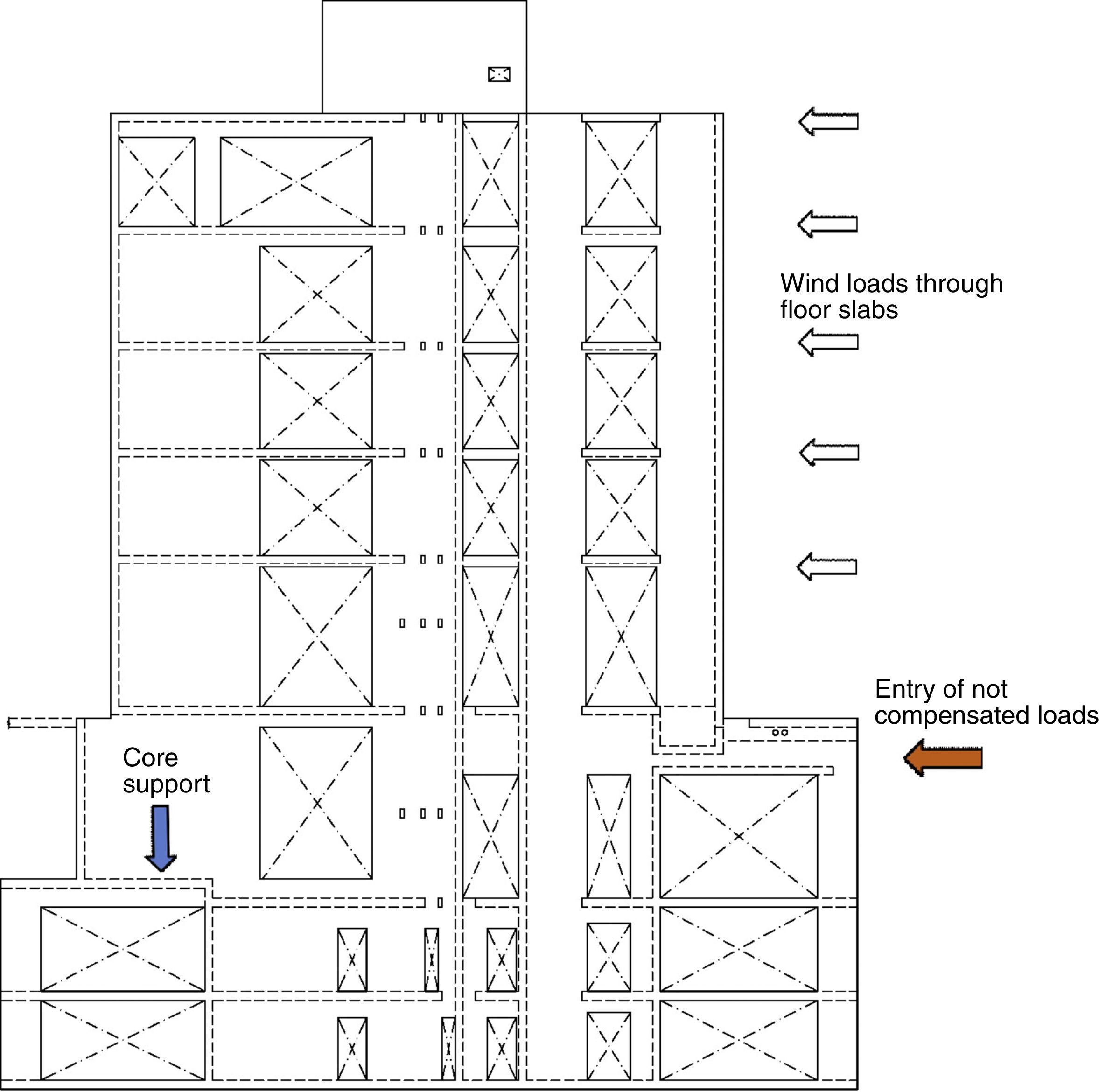
3.2.2Soil pressure load compensation between retaining wallsThe greater height of calle Luca de Tena implies the appearance in the design of soil pressure loads that cannot find compensation on the A-2 motorway side. In this case (above level S02), the loads are driven down to the core of the blocks through the slabs, incorporating precise “membrane” type reinforcement. This mechanism also means there is need for special features for loads to enter in the core walls to be designed (Fig. 14).
3.2.3Loading and unloading area of the office complexTo the extreme east of the development is the delivery entrance and loading and unloading centre. The dock, located on level S02, is accessed via the road parallel to the A-2 motorwayNational Highway II, which is on the same level. Manoeuvrability of the delivery trucks requires a number of the columns of the last block (block D) to be hold up to level N00, thus freeing up the space in front of the dock.
In order to hold columns up, composite dropped beams are used, connected to the slab of N00 thus achieving rigidity and ample capacity for the support [3].
3.2.4Conference hallThe surroundings of the conference hall between blocks A and B is a unique geometric environment, with level changes in the floor structure and movements of columns on all floors between S02 and N01, which means the columns have to be hold up the floor beams.
Once again the construction conditions, together with the strict height restrictions, mean that a composite solution is the most suitable, whereby a smooth and natural constructive transition can be done with dropped steel beams connected to the slabs.
Steel profiles are embedded into the columns so that coupling of the steel beams can be done via provisional bolts, allowing for the quick-release of hoisting equipment, thus avoiding the need for specific shores for the beams. The combined solutions are always of the “shoring” type, in other words, the whole of the load transfer of the beam is done directly on the composite section.
Finally, the roof of the hall is supported on steel beams connected to the slab. The presence of heavy loads from the garden make it necessary to increase the rigidity of the borders and cantilevers with reinforced web floor beams, which are hidden under the earth.
The closure of the perimeter of the conference hall is with double glazing, with an intermediate chamber of 0.80m. This partition materialises in the form of glass sections without horizontal joints, supported on framing in the floor slab, and finished against the roof slab. The compatibility of vertical deformation of the slab and the glass wall require an adjusted assessment of the long-time deflection for the size of the structural silicone joint. Furthermore, the roof slab was preloaded with stockpiles to semi-permanent load levels, in order to obtain the exact measurement for cutting the glass at the point closest to the maximum expected deflection of the roof. The continuous control of deflection has shown a slightly conservative instantaneous and long-time behaviour as compared to the calculation values in accordance with the simplified checking method of long-time deflections of the EHE-08 [4].
For the grandstand of the conference hall an inclined slab with a cantilever 9.40m long is designed, which is resolved by way of a slab, with pre-stressed ribs 0.15m in width, spaced every 3.90m. The live load deflection, and thus the response to vibrations, defines the minimum rib web height as 0.75m, according to the deflection limit of L/800 under characteristic live loads, which is a suitable and common indirect vibration checking procedure.
Cracking is controlled by the use of prestressed bonded reinforcement, which in the form of a cable of 12 chords per beam and with an active anchor at the end of the cantilever, also allows the permanent deflection of the slab to be corrected, maintaining the necessary “upright” exposed presence of the end of the cantilever.
Functionally, air-conditioning conduits run between the beams and the upper side of the slab, ascending from the main branch of the conduit through planned holes made in the slab.
Architecturally, the lower side of the slab is defined as “exposed”, as are the short supports on which it rests, which are covered in “Corten” style steel sheets, directly connected with bolts. Like the composite piles on the bridges, the steel cladding is used as formwork, a load-bearing element, and architectural finish. The finish in terms of tone, durability and functionality, is the subject of special attention from the team of architects, as is the formwork joint composition on the exposed side of the slab (see Fig. 15).
3.3Above ground structureThe geometry of the floor slabs above ground level is repeated on the four blocks, which allows a systematic solution to be considered for all of them. The floor slabs rest on the central core of the block and progress towards the façade, resting firstly and continuously on the first line of columns with a span of 10.40m. The second line of columns recover the unit of 7.80m, but now outside the façade (Fig. 16).
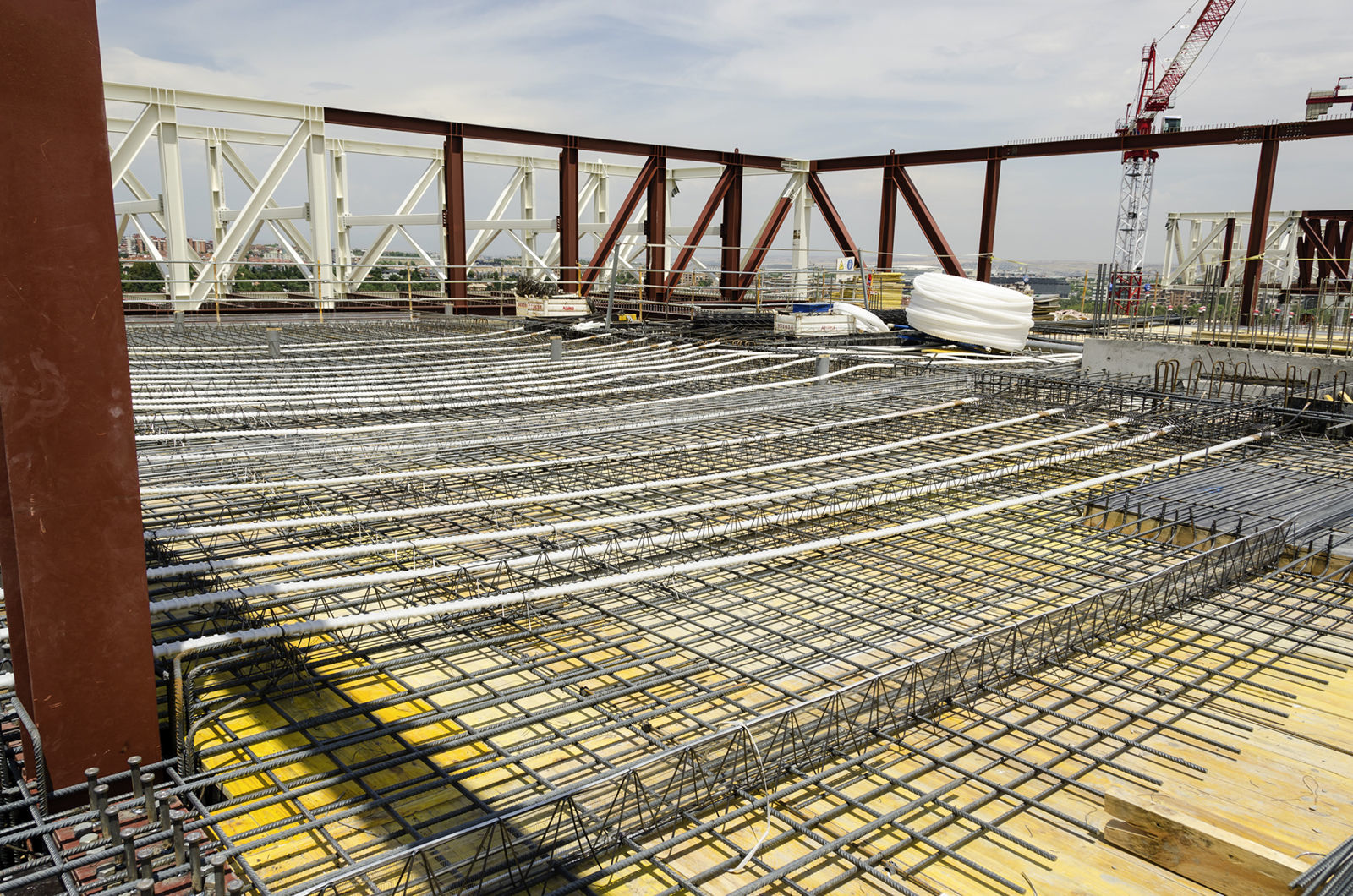
Under these conditions, a lightly prestressed layout is chosen (flat sheaths with three-chord cables every metre, on average), between the support on the core and the façade (Fig. 17). The edge of the slab is maintained at 0.30m, and the chords have been designed as adhesive, injected with grout, which allows for the full use of the active reinforcement at ULS beyond the load compensated by the shape of the cable. The active end is placed on the façade, and the passive end on the core. It is executed by way of a climbing formwork so that the anchors can be placed on the thickness of the wall and cast with the slab.
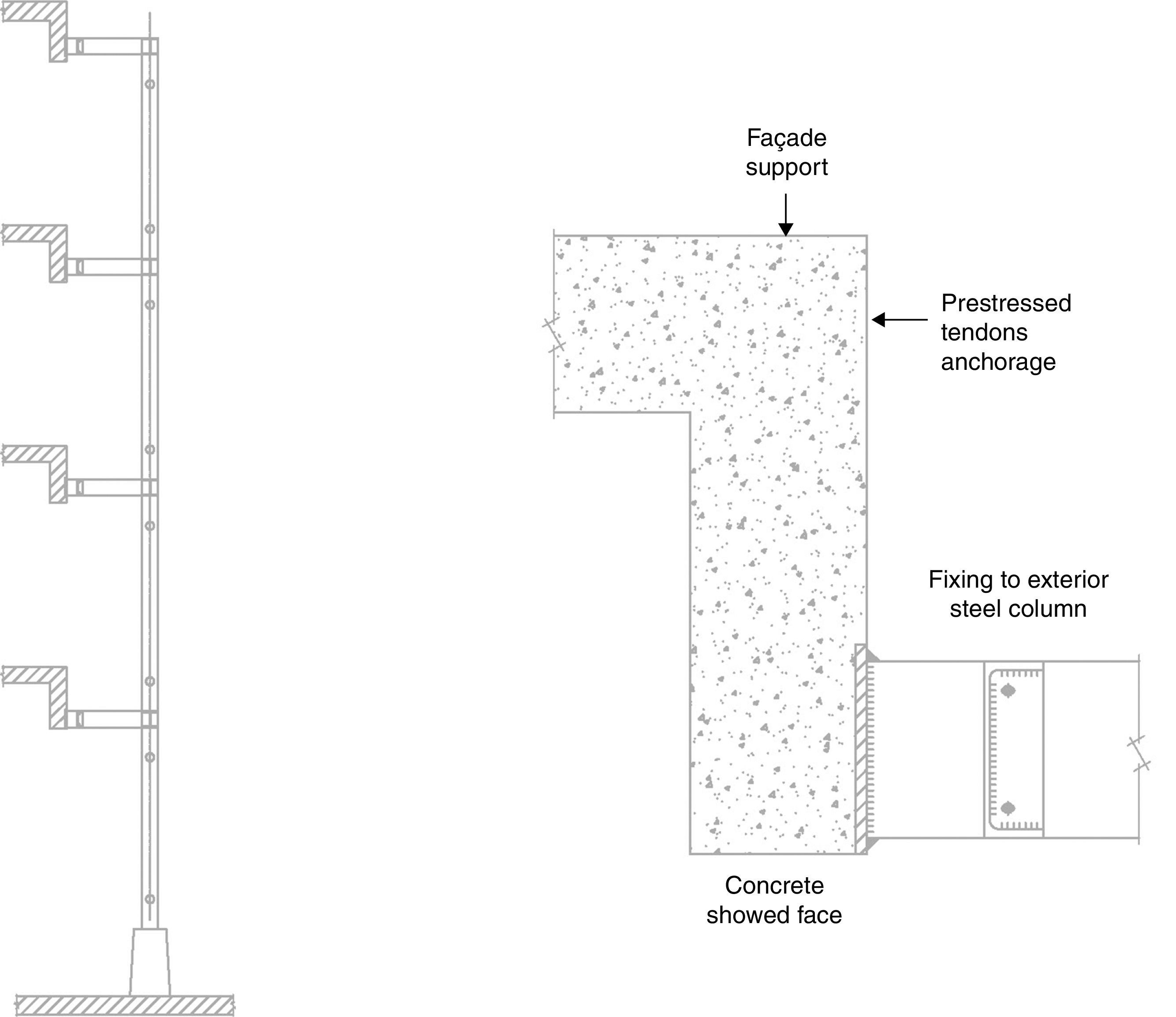
On the external edge of the slab the following must be coordinated (see Fig. 18):
- •
Active prestressed anchors.
- •
Steel cover plate and connection of the slab to the steel façade support. The plate must go through the façade, so that its layout coordinates with the façade unit.
- •
Façade support, which includes potential plates embedded into the edge of the slab
- •
Architectural finish of the slab border.
As a result of the joint efforts of the structural and architectural teams, a solution arises that covers all requirements. The idea is a fold in the slab, by way of an edge girder the same width as the thickness of the slab (0.30m), which incorporates a steel connection piece on the lower edge, thus avoiding interference with the prestressed anchors and the support plates on the façade. The layout of the cables is done taking into account the position and size of the plates on the façade. Finally, the lower side of the girder descends to the level of the lower side of the suspended ceiling of the level, allowing itself to be exposed, framing the contour.
This edge girder also brings improvements to deflection in the edge of the floor slabs and uniformity to the distribution of reactions across the steel supports on the façade, due to its stiffness.
3.4Vertical structure of core and columns3.4.1CoresThe cores of the blocks are formed out of walls 0.25m thick across their full height, which contain stairwells and lifts. Their size is conditioned by the structural functions assigned to them (see Fig. 19):
- •
They receive vertical loads, according to CTE [5], from the slabs they support.
- •
They receive horizontal actions of the wind [5] and the stabilisation of the building columns.
- •
They receive horizontal actions due to the compensation of loads of retaining walls.
- •
They receive horizontal axial forces that the underground floors transmit through the floor slabs and which are due to deformations caused by shrinkage and temperature. The cores, due their rigidity, represent fixed points compared to these displacements.
The presence of holes at the top of the walls suggests that a study by means of models of elastic finite elements of the stresses on the walls should be carried out. Such study is completed with reinforcement analysis, using ties and struts models, of the most unique geometric areas.
In the case of block C, which is offset towards the north compared to the other blocks, part of the core invades the traffic lane in the garage at level S02 and lower. This fact motivates the need to partially prop the end of the core up on each of the columns. This means placing heavy compressions on the supports, and the appearance of considerable shearing forces on the composite beams.
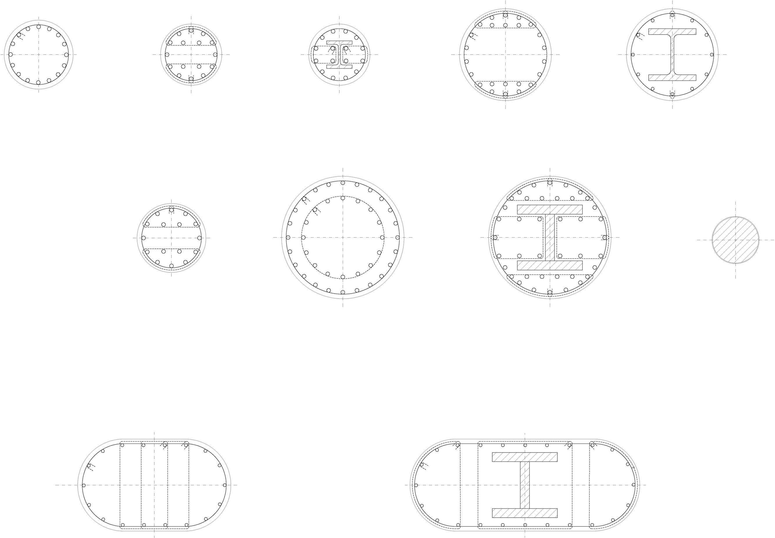
3.4.2ColumnsThe columns for the blocks and the underground levels are conventional reinforced concrete, so in general all exposed columns have been unified as being circular, measuring 0.60m or 0.80m in diameter (Fig. 20).
The greater diameter corresponds to those columns that withstand the weight of the steel roof of the building. There are large steel trusses on the roof that hold the significant cantilevers. This means that the columns have to drive loads that are significantly greater than the loads for the rest of the columns for the building, down to the foundations. In order to keep the loads of those columns heavily on the 0.80m diameter, steel profiles have been embedded into the columns in order to distribute the loads, by bonding them by injection to the rest of the concrete structure.
This way, some of the columns hold the tensile forces, due to the roof, which are likewise transmitted through the steel profiles embedded in the concrete columns. The transfer is by adherence, lengthening the composite profiles in this case only down to level N00, where the tensile forces are comfortably covered by the weight of the slabs.
The embedded steel profiles collaborate from a construction perspective in the assembly of the roof by allowing the trusses to be supported independently of the concrete pouring in the columns.
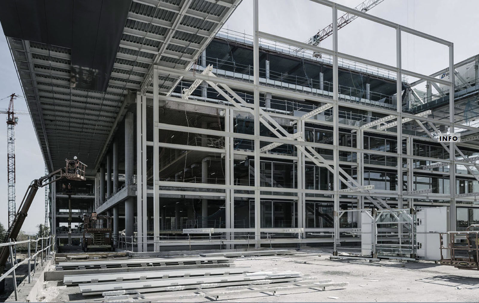
3.5External structure of the façadesFrom the external columns of the blocks a very open steel gantry frame extends, which allows the fire escape stairwell to be supported as well as supporting the sunshades and other secondary elements (see Fig. 21). The main characteristic of the system is its lightness and flexibility, which are translated into the placement of strict braces and stiffeners.
Given that one of the prime conditions of the design is its slenderness, a nonlinear second-order analysis has been carried out of the structure in accordance with 22.3.5 EAE (structural concrete standards) [6], on the basis of a deformation akin to the first overall mode of buckling. With this, reactions have been obtained for the sizing of the joints and the assurance that the bracing and stabilising elements are sufficient.
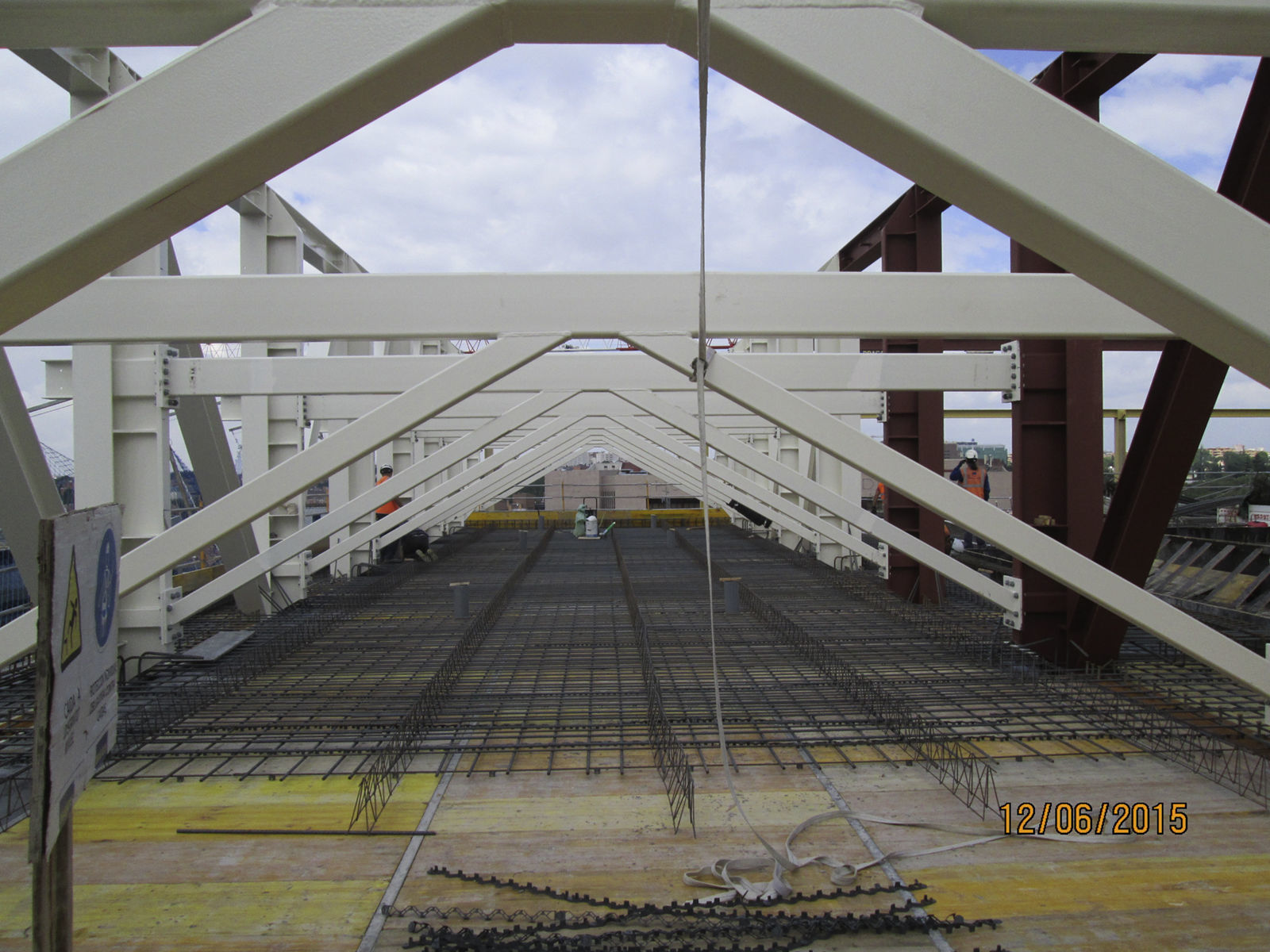
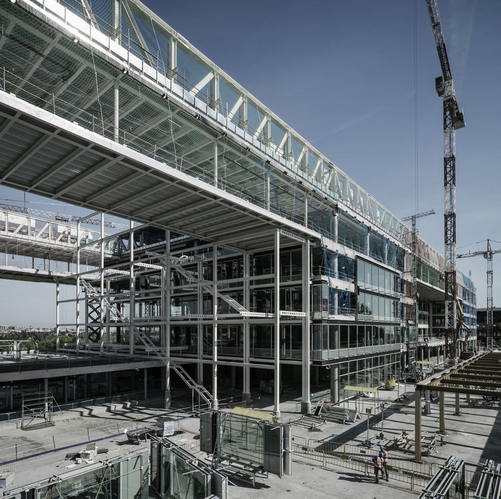
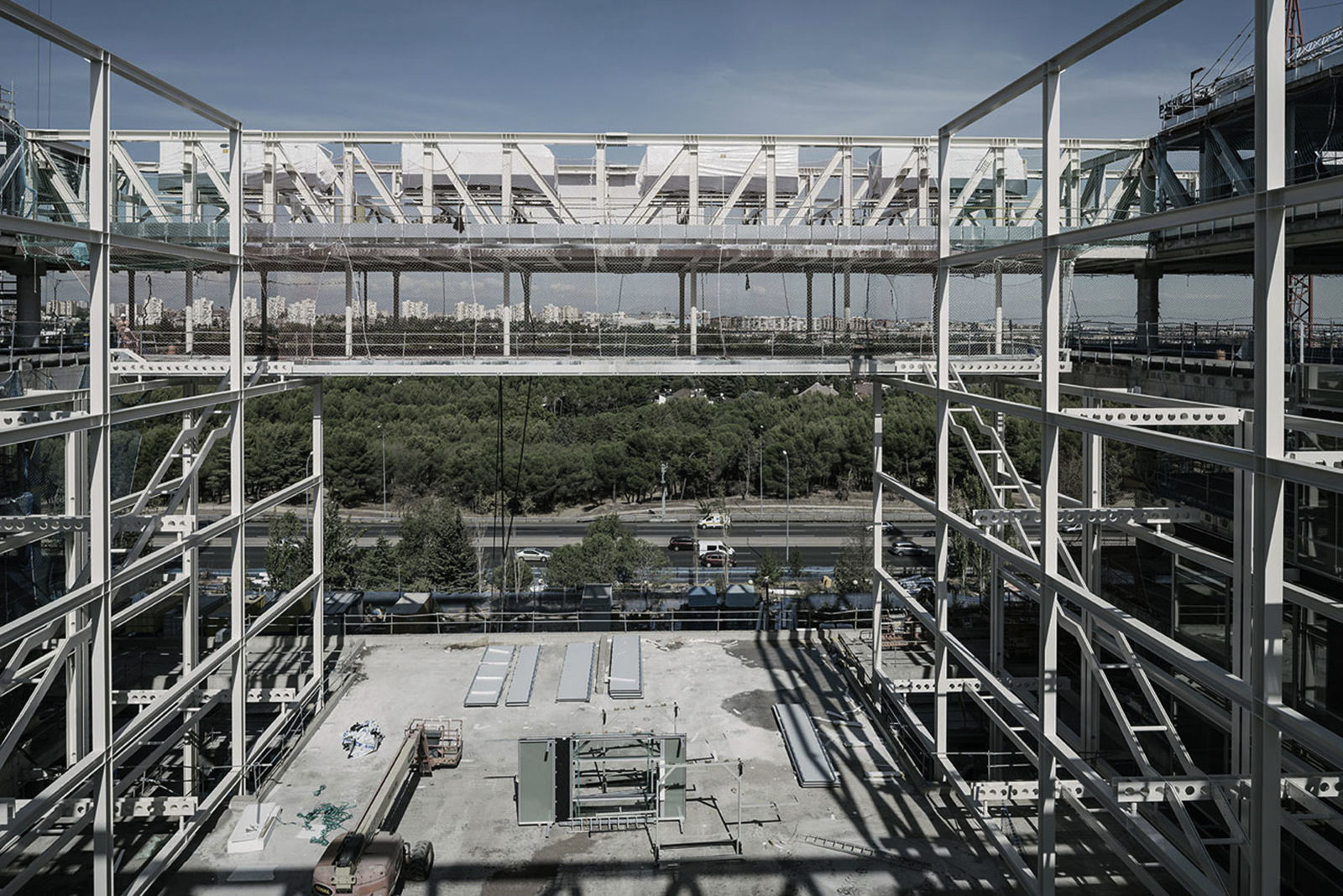
3.6Description of the roof structureTaking into account the determining factors of the project, a system of steel self-supporting trusses are designed, measuring 3.60m in width, which are placed in a grid-like pattern to allow for them to be executed with minimum auxiliary means (Fig. 22).
The height at which they are required to be placed, and the size of the building, means that truck-mounted cranes are needed to lift them, and so the couplings are designed to be bolted, as this will allow for quick and safe provisional pre-assembly to free up the hoisting apparatus.
The pieces manufactured in the warehouse are welded, distributing the joints in such a way that the pieces can be lifted optimally.
The main characteristics of the structure are:
- •
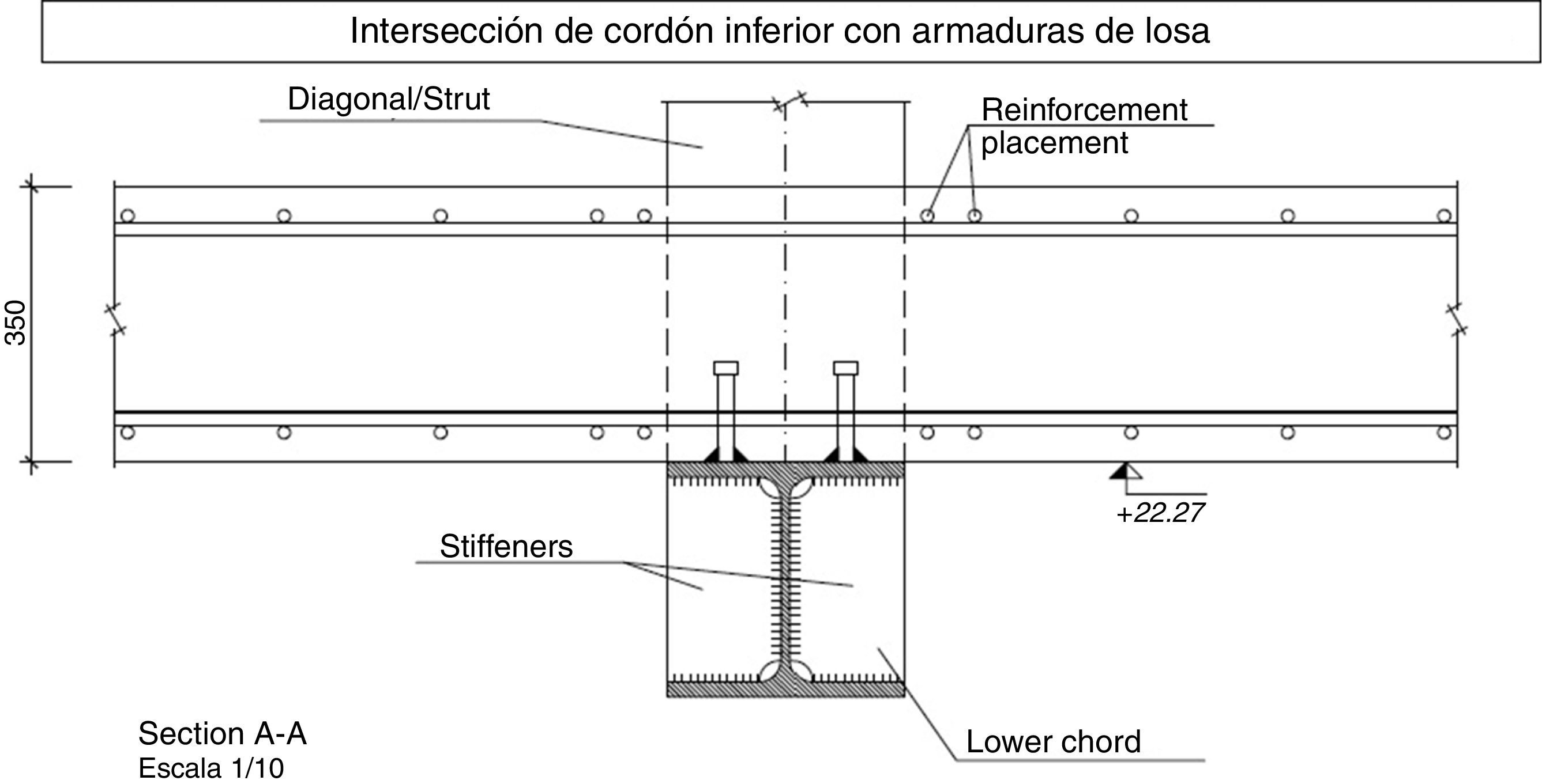
The steel trusses are distributed in such a way that the bottom chord is below the lower face of the roof slab, connecting to the roof slab through a flexible “bolt”-type connection (see Fig. 23).
- •
The diagonal and upright trusses span the flat of the roof. They are partially exposed to the outdoor environment, as is the top chord.
- •
For all “cantilevered” areas, in other words, outside the footprint of the blocks, the type of slab chosen is a composite steel sheet measuring 180mm in total thickness (120+60), in order to reduce weight.
- •
The parts of the slab on the fourth floor suspended from the roof trusses are designed with the same composite slabs for the same reason. The composite slab areas on the roof level are not connected to the bottom chord of the truss due to its reduced thickness (180mm) which significantly limits the connection capacity due to concrete failure. The dimensioning of the trusses is therefore eminently metallic, except locally inside the blocks that are connected to each other, taking advantage of the capacity and rigidity of the solid slabs measuring 0.35m in thickness.
- •
The secondary steel structure for the “suspended” slabs on the fourth and roof levels is made up of joists connected to the slab, with standard spans of 7.80m.
- •
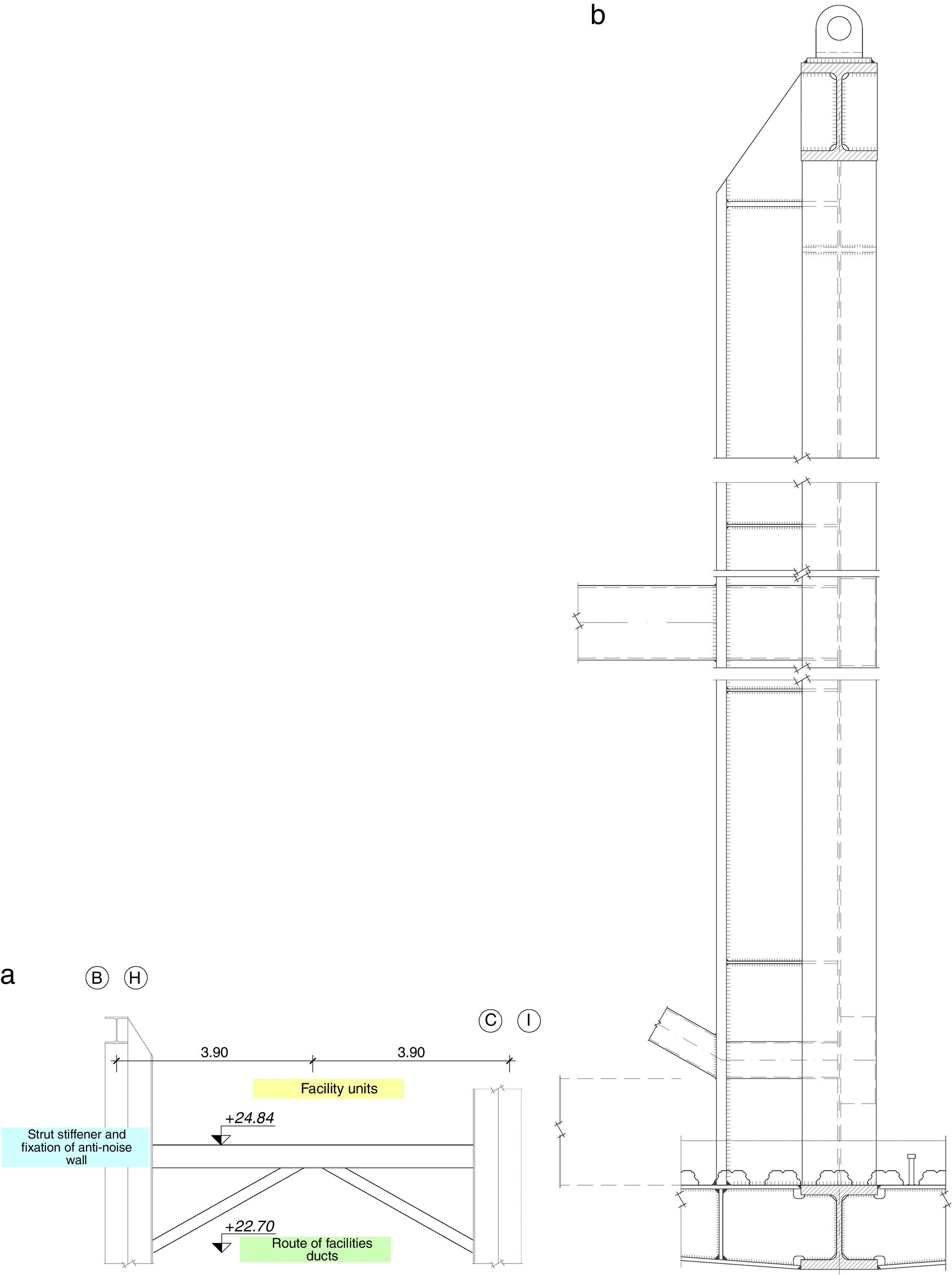
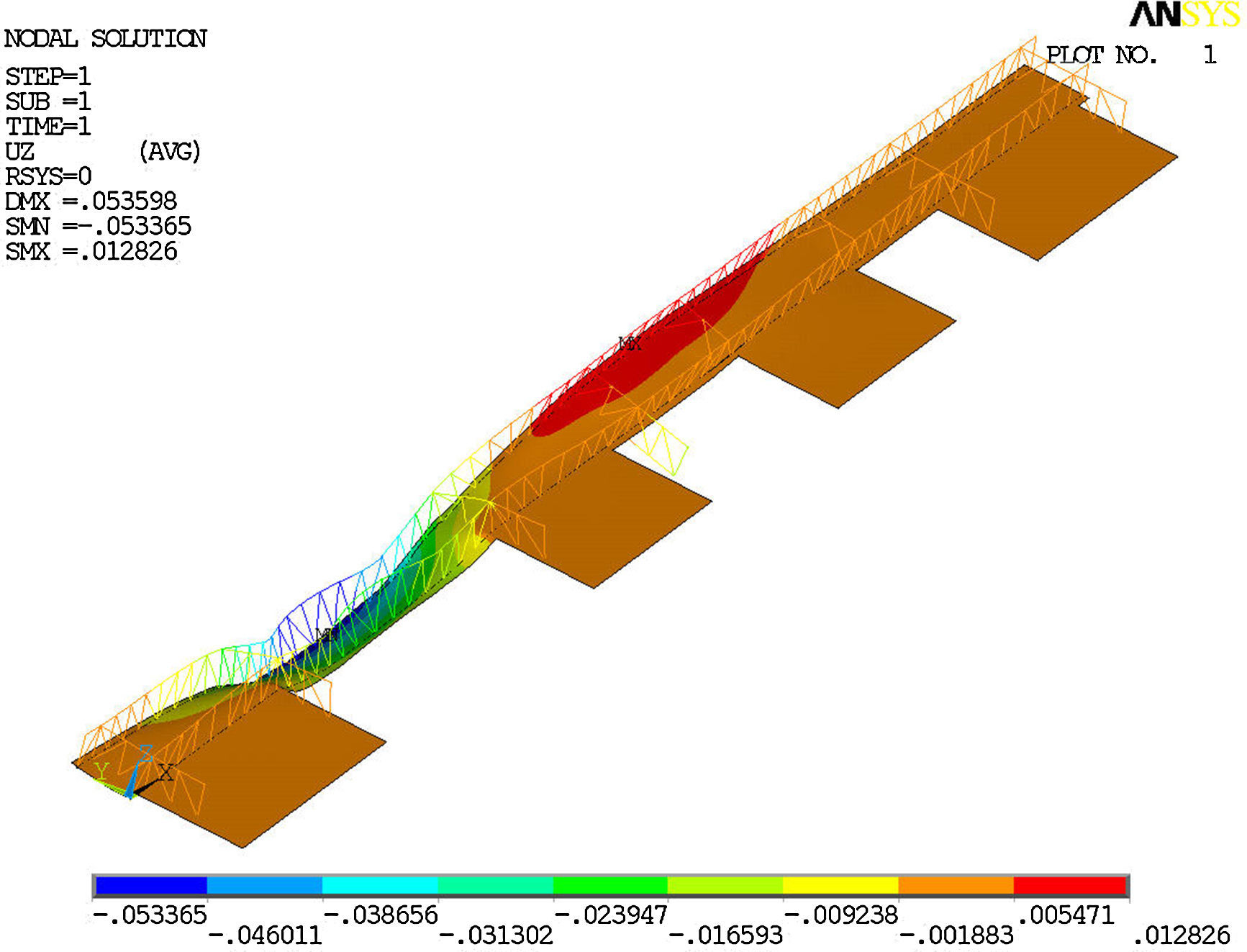
The trusses are placed in continuity in such a way that there are areas in which the top chord is tensioned and others where it is compressed (Fig. 24). This latter requires a strong bracing action on the top chord to avoid buckling. However, all the machinery for the installations of the building are to be located between the trusses, so that it is not possible, other than in rare sections, for bracing between top chords. This leads to the recommendation to incorporate a substructure of supporting frames for machinery to the roof structure. Therefore, a load-bearing system in the form of an inverted K is designed that repeats like a diaphragm every 3.45m or 3.90m, connecting the trusses together longitudinally. The machinery rests on the upper part of the K and the conduits run along the lower part, between the diagonal lines (see Fig. 25).
- •
The previously described system does not connect to the chords directly, however, it does reduce the length of the lateral bending stresses of the uprights and diagonals. The remaining rigidity needed to control the lateral movements is achieved through the stabilisation of the upright post of the truss with an additional T section placed inside, to not interfere with the façade, thus increasing the buckling load of the whole (see Fig. 26).
- •
The roof is designed without expansion joints, it is continuous in such a way that the thermal action is taken into account in the analysis, even in the nonlinear geometric analysis of the roof.
There are several interesting phenomena that are present in the analysis of the roof. These are briefly covered below.
4.1Structural analysis of the roof. Impact of temperatureThe placement of the trusses follows a typology frequently used on railway bridges, for example (see Fig. 27), with the top chord supported elastically in a transversal direction. It therefore depends on the rigidity that the upright and diagonal posts bring to the buckling load of the entire chord (Fig. 28).
As the bottom chord is connected to the slab, and subjected to smaller thermal changes than the top chord (exterior), external thermal increases impose significant increases on axial forces, primarily due to the restricted longitudinal displacement of the top chord that the inclined diagonal posts restrain as they were fixed points. The axial force thus imposed by temperature on the top chords is almost constant along the entire length, independently of the longitudinal size.
The consequences of this are:
- •
The impact of temperature on the top chord generates higher buckling lengths than the equivalent axial forces produced by the bending of the truss itself, because these are variable depending on the distance between columns, whereas temperature axial forces are nominally constant.
- •
Given that restriction points of the longitudinal movement of the top chord in each diagonal post are created, in other words, every 3.45–3.90m, the transversal movement of the chord initiated by buckling does not allow axial forces to be dispersed, as occurs when the fixed points of movement are further separated. Only one form of buckling that has longitudinal restriction point nodes, in other words the node with the diagonals, allows for second order efficient dissipation, of temperature axial forces. Thus the temperature axial forces must be considered in the overall verification of buckling.
- •
Given the high imposed restraint by the bottom slab on the longitudinal movement of the top chord, the impact of temperature on the design is very important. Thermal action must be studied and applied in an adapted manner to avoid oversizing, which can be important and affect extensive areas. Aspects such as sun exposure and orientation of the piece, its colour and the temperature during assembly should be considered in detail.
In general, the design principle has been to try to bring sufficient transversal rigidity to the upright posts through reinforcement and make easier the structure support, to reduce the overall buckling length, adapting it to the distance between diagonal posts.
For the design of the roof, various calculation models were used in order to calibrate the impact of loads on the stability of the top chord and its size. Two groups of models were used:
4.2Columns under compression. Embedded rocker bearingsThe columns that receive the highest compression reactions from the trusses, obviously the last ones before the cantilevers, are also at the level of the roof slab and thus have their horizontal displacement impeded. This requires the top node of the upright bar to displace on a horizontal plane, bringing the upright bar with it. In cases where reactions are greater (up to 27,000kN, design load), the load located on the columns needs to be transferred to a steel profile embedded in the concrete. Its size, imposed by the value of reaction and the geometry of the elements, makes it bring significant rigidity to the columns, which, had it maintained a continuous bend with the top upright post of the truss, would lead to unbearable bending stressed in the upright post. It is therefore necessary to release the rigidity in such a way that the reaction is as centred as possible on the columns.
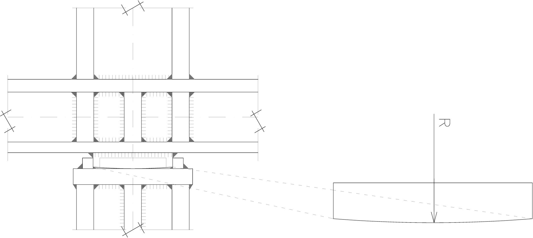
To that end, spherical rocker bearings [7] have been designed on those points through the manufacture of structural steel pieces, which allow significant fixed bending forces of the embedded profile to be released. The cladding of the reinforced concrete column is extended up to its connection, using minimum reinforcement, to the slab in order to receive the constant horizontal forces transmitted by the truss. This allows the spherical bearings to be protected, as they are embedded (Fig. 30).
Spherical rocker bearings (R=4000mm) on composite columns [6].
Given the size of the roof, any condition that the structure must fulfil for its execution must be defined at a project level in order to be included in the planning and forecasts for the project.
The criteria established in the project for the assembly were the following:
- •
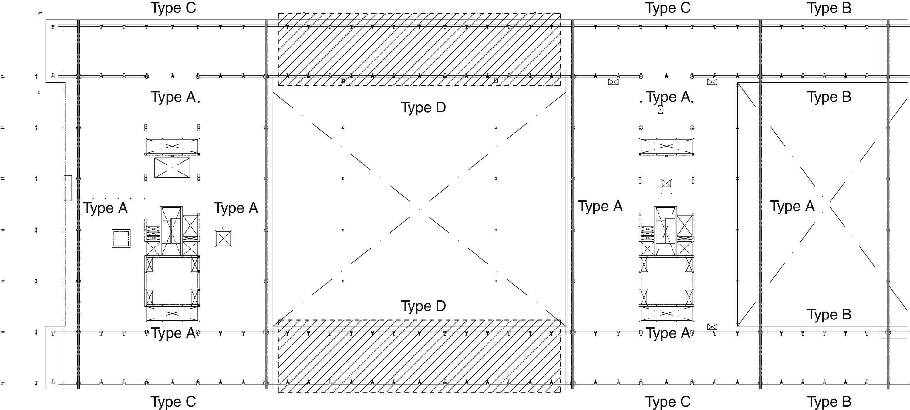
The truss pieces (Fig. 31) can be grouped by: (A) those that can be assembled using the bottom slab as a platform, (B) those that do not have a bottom slab due to being on cantilevers or bridges, but their size and placement allows them to be positioned using a truck-mounted crane, (C) those that do not have a bottom slab, due to forming part of bridges, but due to their size the optimum assembly solution could be hoisting with a system of cables and hydraulics or using a truck-mounted crane and (D) those that do not have a bottom slab, due to forming part of bridges, but due to their size the most suitable assembly solution is hoisting using a system of cables and hydraulics.
- •
Type A trusses are practically all transversal trusses (parallel to the north-south axis). Type D are specific to the large bridges between blocks A and B, which due to their size and position allowed the full assembly of the bridge on the access level, including the secondary beam structure and the decking plate of the slabs and the beams and lower fourth floor.
- •
Type C trusses were identified in the project as being susceptible to hoisting, however geometric conditions and location impeded that pre-assembly at floor level included composite slabs. In this case the constructor (Dragados and Horta-Coslada) proposed that assembly be carried out using a truck-mounted crane.
- •
All couplings in the project were designed with pre-tensioned bolts, no slip in SLS.
- •
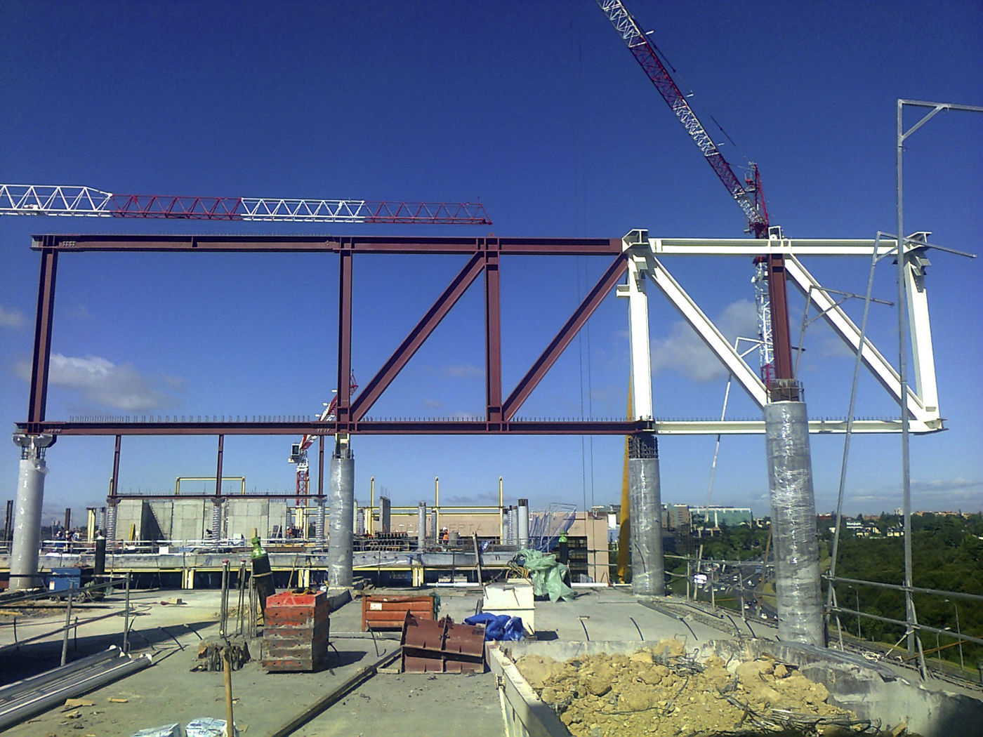
Type A trusses rest on columns. In order to separate the works of placement of the steel truss structure from the reinforcement and concreting works on the columns and roof slab, the project defines the placement of the embedded steel profiles within the columns that are to receive the load. This way it is possible to correct, if necessary, possible tolerances transferred in the execution of the concrete structure, by placing the steel profiles in the correct position. In those cases where the columns receive heavy vertical loads, or tensile stresses, the embedded steel profiles are not only assembly pieces, they also perform the dual task of transferring loads to the rest of the concrete structure (Fig. 32).
As regards the “bridges”, the assembly process is defined under the following general terms:
- •
With the type A supported on the blocks trusses in position, the hoisting and assembly is carried out by way of bolted joints in the sections found on the vertical plane of the framework for the fire escape, and thus they cannot be hoisted. On those sections placed on a cantilever, hoisting units would be available.
- •
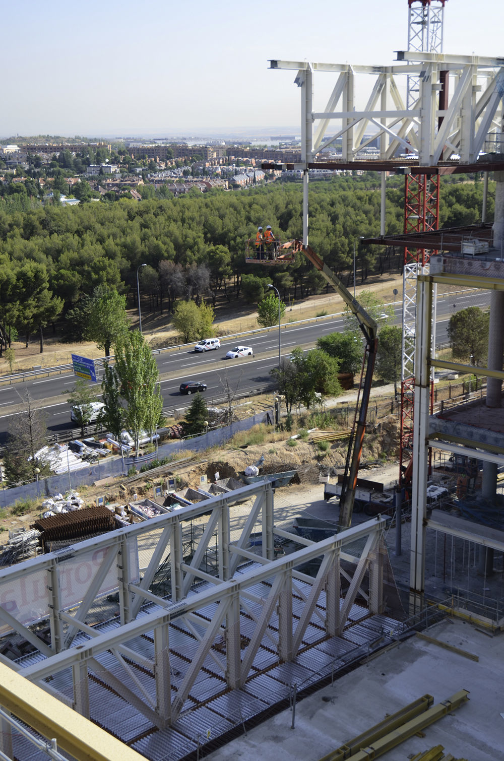
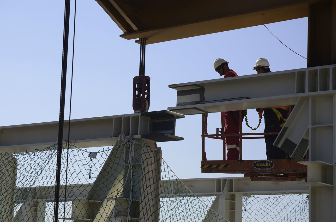
The two trusses of each bridge, the bottom beams of the slab and the decking plate are assembled on provisional frames. The suspended beams of the N04 level, its secondary beams and decking plate are also assembled (Fig. 33). The total weight of each “bridge” is approximately 2500kN.
- •
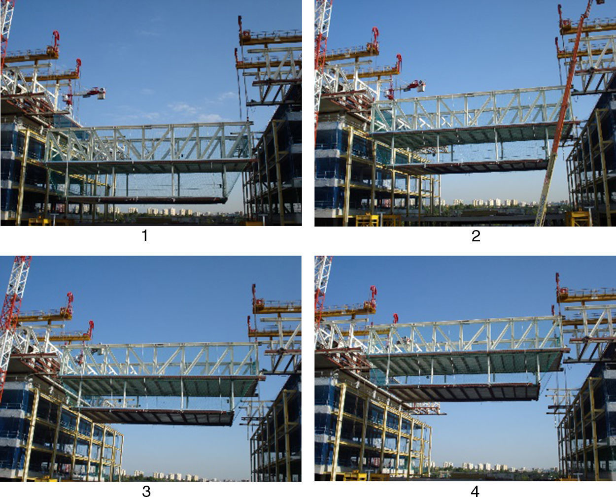
The whole, as assembled, is lifted into position by way of hoists with four pullers. The couplings are done (Figs. 34–36).
The new Banco Popular Headquarters is consistent with a corporate architecture that requires the design to have an architectural expression that is recognisable to employees, clients, visitors and the general public. In this building, the structural design reinforces and promotes this image bringing a representative value of the highest order, as well as bringing technical and building solutions that allow construction processes to be improved.
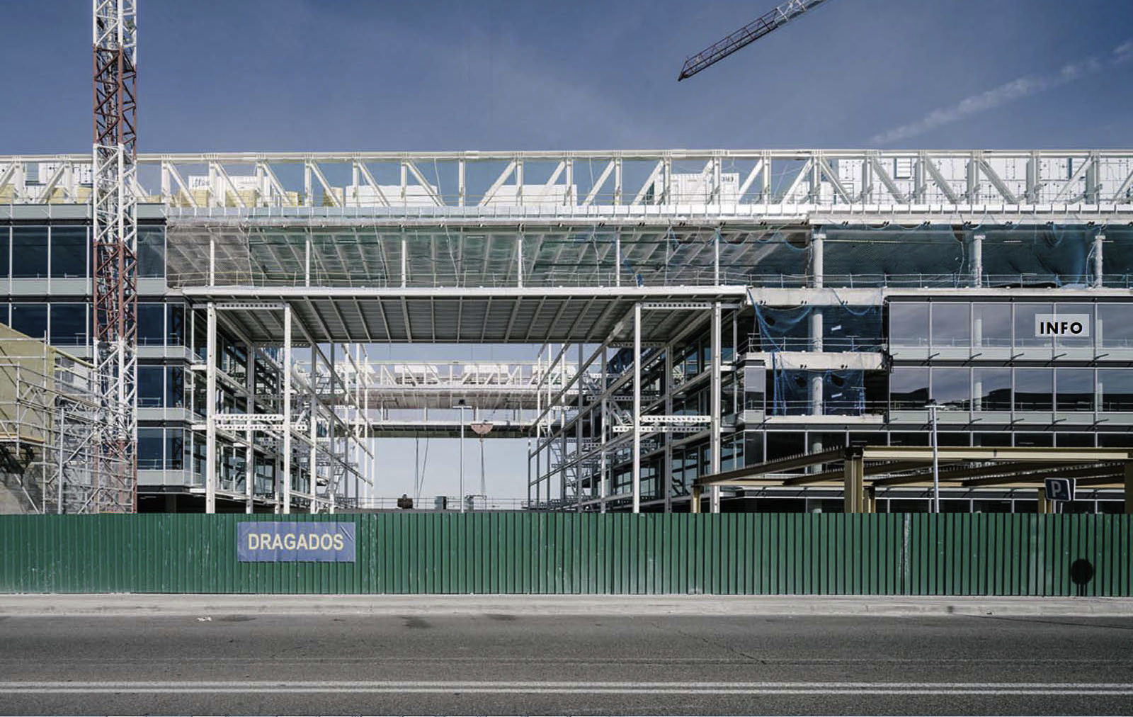
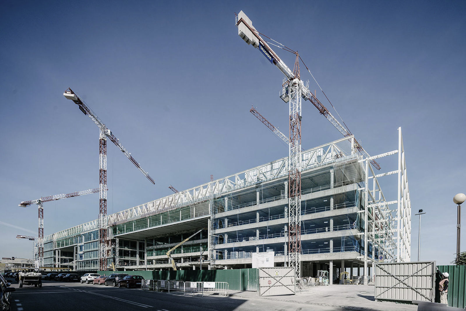
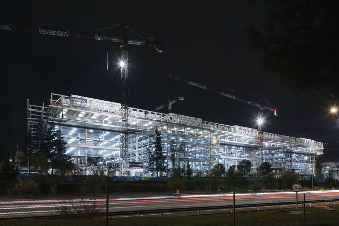
Thus, this is a building that does not renounce its uniqueness one iota, and yet, it is extremely efficient in its use of resources (Figs. 37–39).
A fundamental characteristic in the development of the project is the smooth and efficient work of the architectural and structural teams from the first analysis phase right up to the finishing touches. This way of working has allowed structural solutions to be implemented that have always contributed to the comprehensive development of the architectural expression required by its designers, contributing to optimum technical solutions from a technical and construction perspective.
7ParticipantsOwner: Banco Popular
Architectural design and Construction Management: Arquitectos Ayala (Gerardo Ayala, Mateo Ayala and Marcos Ayala)
Structural Design and Technical Assistance to the Construction Management: MC2 Estudio de Ingeniería (Grupo Typsa)
Project management: Bovis
Construction: Constructora San José (retaining walls and excavations), Dragados (general structure), Horta (metal roof structure), Tauxme (exterior metal structure), Ale Heavylift (roof hoists), Freyssinet (prestressing).





![New Data Processing Centre building at calle Abelias (stage I) [4]. New Data Processing Centre building at calle Abelias (stage I) [4].](https://static.elsevier.es/multimedia/04395689/0000006900000284/v1_201804250433/S0439568917301079/v1_201804250433/en/main.assets/thumbnail/gr3.jpeg?xkr=ue/ImdikoIMrsJoerZ+w96p5LBcBpyJTqfwgorxm+Ow=)


![Finite element analysis of (ANSYS®) of the filtration volume beneath the retaining walls. Dimensioning study of the depth of embedding the retaining walls, dimensioning of the drainage network and subsequent up-lift loads on neighbouring foundation elements (drainage wells, septic tanks, footings, etc.). Pressure contours (above left [m]), filtration volume (below left [m3/s]) stream lines (right) of a retaining wall cross-section, calle Luca de Tena. Finite element analysis of (ANSYS®) of the filtration volume beneath the retaining walls. Dimensioning study of the depth of embedding the retaining walls, dimensioning of the drainage network and subsequent up-lift loads on neighbouring foundation elements (drainage wells, septic tanks, footings, etc.). Pressure contours (above left [m]), filtration volume (below left [m3/s]) stream lines (right) of a retaining wall cross-section, calle Luca de Tena.](https://static.elsevier.es/multimedia/04395689/0000006900000284/v1_201804250433/S0439568917301079/v1_201804250433/en/main.assets/thumbnail/gr11.jpeg?xkr=ue/ImdikoIMrsJoerZ+w96p5LBcBpyJTqfwgorxm+Ow=)


![Analysis of the roof trusses. North façade. Vertical displacements [m]. Analysis of the roof trusses. North façade. Vertical displacements [m].](https://static.elsevier.es/multimedia/04395689/0000006900000284/v1_201804250433/S0439568917301079/v1_201804250433/en/main.assets/thumbnail/gr28.jpeg?xkr=ue/ImdikoIMrsJoerZ+w96p5LBcBpyJTqfwgorxm+Ow=)

![Spherical rocker bearings (R=4000mm) on composite columns [6]. Spherical rocker bearings (R=4000mm) on composite columns [6].](https://static.elsevier.es/multimedia/04395689/0000006900000284/v1_201804250433/S0439568917301079/v1_201804250433/en/main.assets/thumbnail/gr30.jpeg?xkr=ue/ImdikoIMrsJoerZ+w96p5LBcBpyJTqfwgorxm+Ow=)


