Introduction
Scientific research in kayak flatwater paddling is mainly oriented: to analyse physiological responses to different tests1-12, to determine kayak paddling biomechanics13-16, to study anthropometric-somatotype of the paddlers17,18 and to assess overuse injuries19. However there is no research that provides a comprehensive description of the dynamics of the paddle movement.
In the mid 1980's a new paddle was designed called 'wing paddle' because its cross section is shaped like an airplane wing. The main difference between a wing paddle stroke and a traditional stroke is that the first one moves sideways, away from the boat, while the traditional one moves parallel to the boat. It is because the wing paddle is concave on the bottom side and in this way water flowing across the blade provides forward lift on the paddle, following the Bernoulli effect.
The interaction of the blade and the water is split into drag (D) and lift (L) forces acting parallel and normal respectively to the direction of the blade motion (relative to the water)20. The drag force on the blade acts to resist the motion of the blade and has a component in the propulsive direction of the boat. Lift forces however act perpendicular to the direction of relative flow. The magnitude of lift and drag forces acting to propel the kayak vary depending on the angular displacement of the paddle in the sagittal plane relative to the kayak21.
Examining the mechanics of vortex-rings, less energy passed through to the water and was lost by a wing blade moving diagonally from the kayak than for a traditional blade moving parallel to it. The wing blade raised the efficiency from 74% to 89% compared to the traditional model because the resulting vortex area was much larger with the wing paddle than that produced with the traditional one20.
We have only found one study to quantify the path and orientation of the blade22. The orientation of the submerged blade and the path of the centre of the blade were estimated from the known position of a marker projected from the paddle shaft in seven male and one female New Zealand National paddlers.
The results indicated that the paddlers varied considerably in their techniques. In particular, the paths of the blade centres varied considerably. All subjects moved the blade laterally away from the kayak until near the time of exit. At entry there was rapid motion in the forward as well as lateral directions. From about 0.07 to 0.1 seconds after entry of the tip, the blade centre had stopped its forward motion and begun moving backwards. The main variability among subjects was in the amount of backward movement of the blade.
Our aim is: a) to quantify the path of the blade in a group of six elite kayakers from the Spanish national team and define the area swept by it in its aerial and aquatic movement, and if no significance differences are found and b) to define the optimal stroke profile (OSP).
Methods
Subject
We present the case of six Olympic flatwater kayakers (age = 25 ± 2 yr, ± 5 cm, body mass = 87 ± 4 kg, BMI = 27,0 ± 0,1 kg m-2, seated ,8 ± 0.5 cm), who train regularly about 28 hours/week. Anthropometric data available for male elite sprint kayak paddlers (table 1) suggest a homogenous shape and size, and are in the range of morphological characteristics of this population23.
Experimental protocol
We analyse the 60 seconds of film recorded in the laboratory, two months before the Athens 2004 Olympic Games. Every kayaker completed a warm-up session seated in the kayak ergometer (Kayak ergometer, Dansprint Aps, Hvidovre, Denmark), at submaximal intensity to acclimatise himself to the paddling task and the laboratory environment. At the experimenter's signal, the kayaker performed a maximal sprint for 60 s, with encouragement from the technical director. The kayaker was not given any recommendations concerning the kayak technique.
Kinematic testing
Instrumentation
A three-dimensional videography system was employed (Kinescan®/
IBV, Valencia, Spain). The capture module comprises four digital video cameras (CCTV Color, SSC-DC58AP, SONY) equipped with a flash system, and film with a sample rate of 50 Hz. Each couple of video camera and flash is placed 3 m height, in each corner of a laboratory (area = 42 m2).
The camera calibration required the calculation of the mapping between the 2D image space coordinates and the 3D object space coordinates. The DLT (Direct Linear Transformation) method uses a set of control points. The control points are fixed to a rigid frame, known as the calibration frame. We use a cubic cell of 8 m3 (PRODUC-0421-KIN_ ACC Sist.Referencia 2x2x2, Kinescan®/IBV, Valencia, Spain).
The paddle model was described using spherical (diameter = 25,48 mm) reflective markers (MKR-25.4, B and L Engineering, California, EEUU), placed at its extremities.
Data analysis
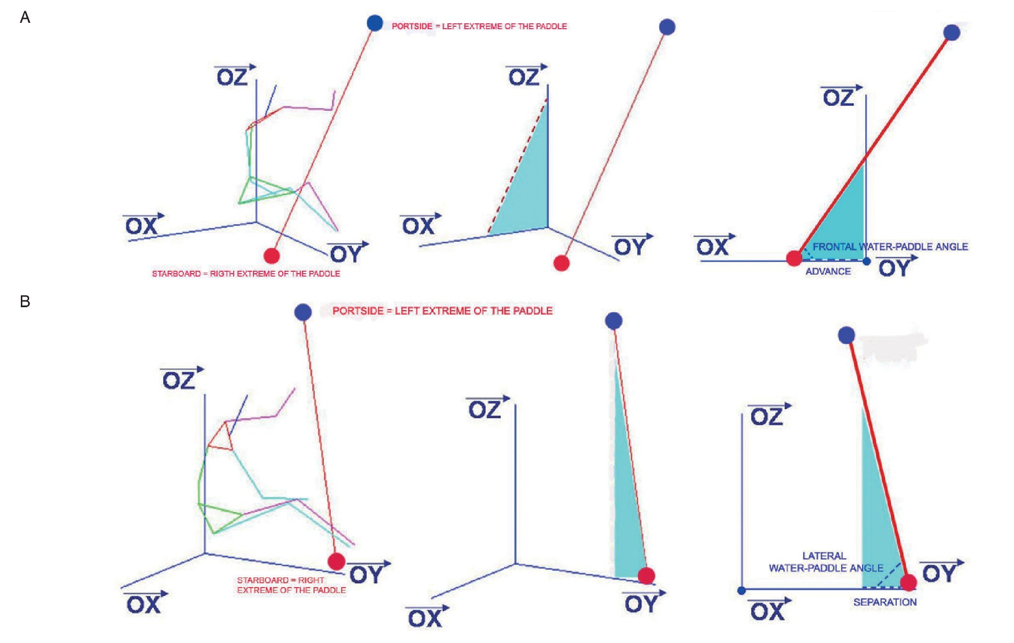
We had to develop a computing tool that using the results obtained with Kinescan®/IBV could calculate the variables at the critical moments. The code and the guide were designed with Matlab 7.024. The kinematical variables calculated were: 1) Spatial variables (fig. 1):
Fig. 1. A) 3D view of the kayaker with the paddle, and the definition of the advance and the frontal water-paddle angle. B) 3D view of the kayaker with the paddle, and the definition of the separation and the lateral water-paddle angle.
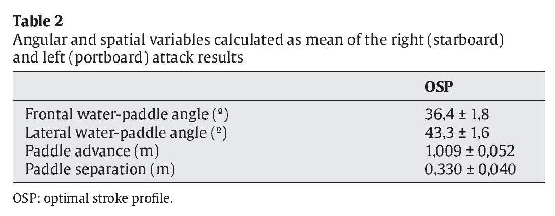
- Paddle advance (PA): defined as the distance along the kayak where the paddle enters the water.
- Paddle separation (PS): defined as the distance perpendicular to the kayak where the paddle enters the water.
2) Angular variables (fig. 1):
- Frontal water-paddle angle (FA): defined as the angle between the paddle and the plane of the water projected in a frontal view.
- Lateral water-paddle angle (LA): defined as the angle between the paddle and the plane of the water projected in a lateral view.
All of them calculated starboard (s) and portside (p).
Spline functions of fifth order were used as the smoothing technique, and the generalized cross-validation (GCV) method was used for the selection of smoothing parameters.
Statistical analysis
PA, PS, FA and LA were calculated in all the starboard attacks (PAs, PSs, FAs and LAs) and in all the portside attacks (PAp, PAp, FAp and LAp) in the 60 s film recording of each paddler. One stroke was chosen for each kayaker, as the stroke more similar to the mean. Once the six strokes (one per kayaker) were chosen, they were normalized to percentage of stroke and the mean of all of them is defined as the OSP.
All data were analysed by statistical software (SPSS version 12, SPSS Inc., Chicago, USA) using analysis of variance (ANOVA) with repeated measures (stroke). Statistical significance was set at p = 0.01 and reported as actual P-value25.
Results
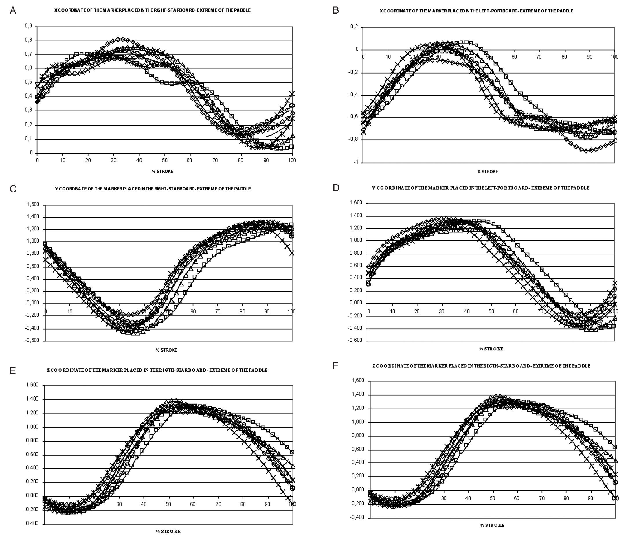
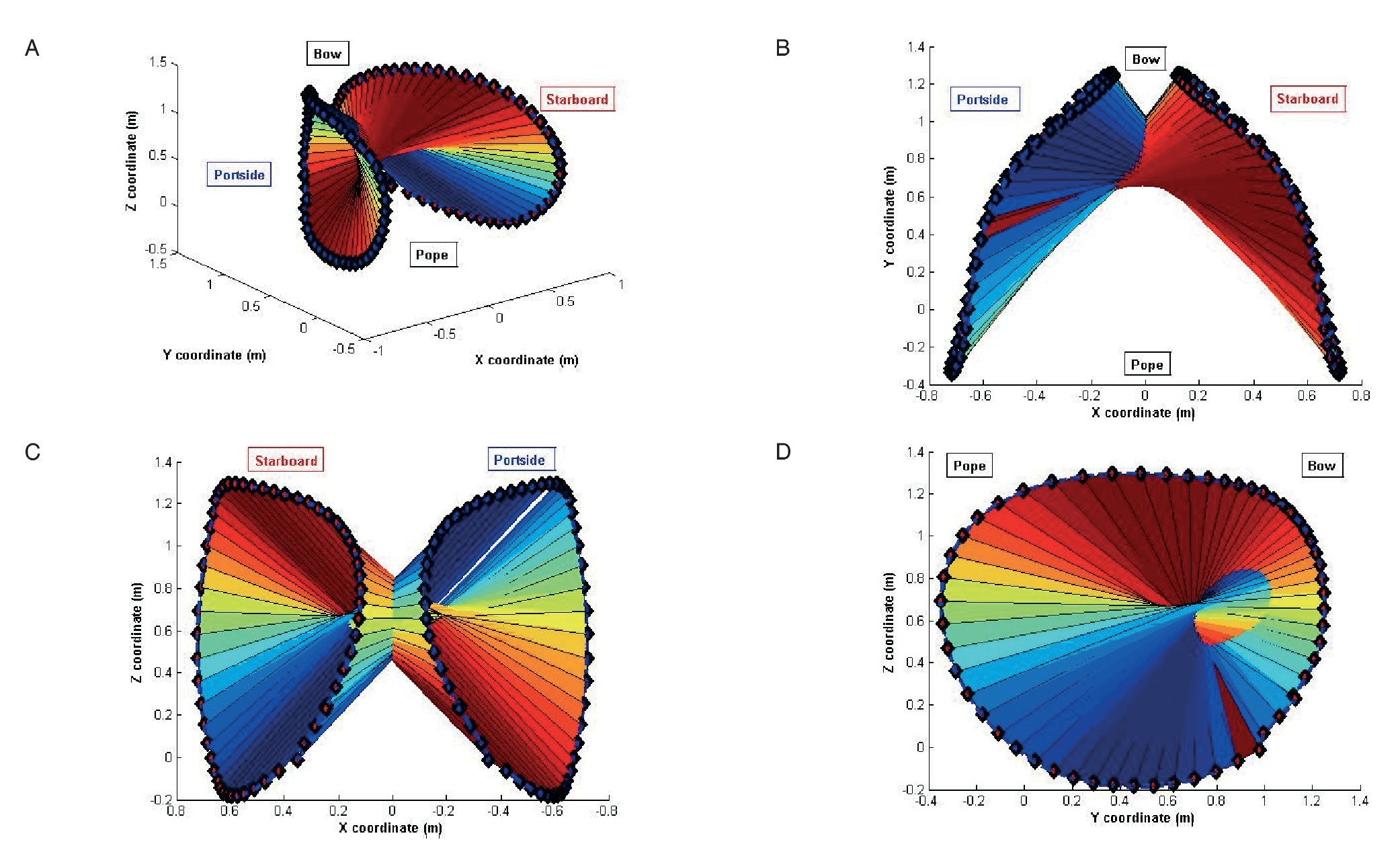
The results of the x, y, z coordinates of the markers placed in the right (starboard) and in the left (portside) extreme of the paddle are shown in figure 2. Spatial variables calculated along the stroke of the six kayakers are shown in figure 3. No significant differences were observed between the strokes of the six paddlers, so we define the OSP as the mean of the six strokes. Figure 4 shows the OSP in a three-dimensional, zenital, frontal and lateral view. Blue marker is the one placed in the left (portside) extreme and red marker is the one placed in the right (starboard) extreme. The coloured surface is the area swept by the paddle in its aerial and aquatic movement, calculated as the mean of the strokes of each kayaker.
Fig. 2. A) X coordinate of the marker placed in the right (starboard) extreme of the paddle. B) X coordinate of the marker placed in the left (portside) extreme of the paddle. C) Y coordinate of the marker placed in the right (starboard) extreme of the paddle. D) Y coordinate of the marker placed in the left (portside) extreme of the paddle. E) Z coordinate of the marker placed in the right (starboard) extreme of the paddle. F) Z coordinate of the marker placed in the left (portside) extreme of the paddle. *Kayaker 1; Δ Kayaker 2; ○ Kayaker 3; □ Kayaker 4; ◊ Kayaker 5; x Kayaker 6; Mean ¿ optimal stroke profile.
Fig. 3. A) Frontal water-paddle angle. B) Lateral water-paddle angle. *Kayaker 1; Δ Kayaker 2; ○ Kayaker 3; □ Kayaker 4; ◊ Kayaker 5; x Kayaker 6; Mean ¿ optimal stroke profile.
Fig. 4. A) 3D view of the OSP: optimal stroke profile (OSP). B) Zenital view of the OSP. C) Frontal view of the OSP. D) Lateral view of the OSP.
Table 2 gives the angular and spatial variables calculated as the mean of the right (starboard) and left (portside) attack results.
Discussion
The results obtained prove that there is no significant difference between the kinematic variables that define the strokes of the six kayakers. Taking into account that the paddlers are kayakers of international competitive level in the 500 m and 1000 m sprint flat-water events who got excellent marks, we can consider that the biomechanics of their paddling technique is an effective one. Once we calculate the mean of the six strokes, the OSP is defined as the canon of the ideal stroke, the envelope of a model paddling that marks the spatial limits for an optimal performance. Any deviation from the OSP can reduce the effectiveness of the paddling.
The main disputable point of this study is that all tests were realized in a kayak ergometer and differences in technique between kayak ergometry and on-water kayaking might alter the results. However, the kayakers of this research are used to training with ergometers, their paddling technique in it is very assimilated, and the advantage of the laboratory test is that the environmental conditions (air temperature, wind speed and its direction, the waves produced and relative humidity may affect an athletic performance) are the same for all subjects.
The latest advance in the kayak equipment is a swivel seat1. A recent study concludes that there's a 6.5% increase in power output using a swivel seat, which could be a significant advantage during on-water competition if the results from ergometer test transfer. It would be interesting to analyse if there's any change in paddle movement, or if it only affects to the muscle recruitment during the kayak stroke.
Correspondence:
C. López López.
Centro Andaluz de Medicina del Deporte. Glorieta Beatriz Manchón s/n.
41092 Sevilla. España.
E-mail: covadonga.lopez@juntadeandalucia.es
History of the article:
Received January 9, 2011
Accepted May 13, 2011


