


The aim of this study was to compare the efficiency of multiplanar reformatted images and three-dimensional images created after multidetector computed tomography examination in detecting acute post-traumatic osseous pathology of the skeletal system.
METHOD:Between October 2006 and December 2008, 105 patients with a history of acute trauma were referred to our service. Patients were evaluated with multidetector computed tomography using multiplanary reconstructed images initially (R-I), and six months after this initial evaluation, three-dimensional images were assessed of each patient (R-II). Axial images were used for guiding as a reference Data obtained was recorded and graded according to importance levels of the pathologies.
RESULTS:The R-II score was higher in the non-articular and highest in periartricular fractures of the extremities, and thoracic and pelvic cage injuries. For the spinal column, while R-I data was more significant In patients referred with polytrauma, R-II data, was more statistically significant, for short processing and adaptation time to acquiring immediate critical information. For all cases it was seen that three dimensional scans were more efficient in providing the orientation, within a short time.
CONCLUSION:By dual source multidedector tomography systems trauma patients may be evaluated by multiplanary and three dimensionally reconstructed images. When used correctly, three dimensional imaging is advantageous and can help determine the exact nature and extension and also importance of osseous injuries.
With recent developments in computerized tomography technology, multidetector computed tomography (MDCT) enabled better volume imaging and high-speed data acquisition,1 allowing both increased coverage and improved resolution with less exposure to radiation, particularly in trauma patients.
Parallel advances in image processing software and hardware warranted designing better examination protocols that optimize image quality for easy and quick interpretation and minimize radiation dose.2
The aim of this study was to compare the efficiency of multiplanar reformatted (MPR) images and three-dimensional (3D) images created after multidetector computed tomography (MDCT) examination in detecting acute post-traumatic osseous pathology of the skeletal system. We also set out to form a short guide to the use of 3D MDCT on trauma patients that would save this method from arbitrary application.
MATERIALS AND METHODBetween October 2006 and December 2008, 105 consecutive patients (average age: 37, F = 30, M = 75) referred to our clinic with a history of acute trauma were retrospectively evaluated. MDCT was performed on a 16-MDCT scanner (Somatom Definition, Siemens Medical Solutions, Germany). with tube voltage, 120-140 kV; effective tube current, 240-280 mAs; section thickness 2 mm; reconstruction interval: 0.75 mm; and collimation 0.6 mm. During the scan, the automatic dose control system was activated to prevent excessive radiation exposure.
Average scan time was between 11 and 23 seconds according to the different region of interest (ROI) settings. In 3 cases, 1 with a suspicion of pathological fracture after the first examination, and 2 with identified vascular injury, an intravenous non-ionic contrast agent (iohexol 1-1.2 ml/kg) was used. All the other examinations were completed without administration of contrast. Scans with contrast were applied in emergency settings, no bolus tracking method was applied, and scans were obtained in the arterial phase with 25-30 sec as delay time.
After axial scanning, thin section reconstructions were also generated by reconstruction in both soft tissue (B10-soft tissue) and bony kernels (B 70-sharp osteo). In both convolution kernels, single data with a slice thickness of 2 mm (1.5 mm reconstruction increment) were used to form the reconstructed images. These reconstructed thin section images were transferred to a special workstation (Leonardo Running Inpace, Siemens Medical Solutions) and then multiplanar reformat (MPR), maximum intensity projection (MIP) and 3D images were generated.
Assessments were performed by a radiologist on sophisticated multidisplay screens. Axial and MPR images were evaluated immediately after each shot, and data were recorded as record I (R-I).Six months after the initial assessment of each patient, only the axial and 3D images were regenerated and evaluated again by the same radiologist. The data obtained were recorded as record II (R-II).
During R-I evaluation, MPR images were examined in coronal, sagittal and if needed in curved or oblique planes. In R-II evaluation, 3D images were examined by rotating the image fully around the coronal and horizontal axis (if needed in oblique positions) at least once. 3D images were first produced from the skin surface to the soft tissues, and then to the bony structure surface by changing the window settings. Both the volume rendered (VR) and surface shaded display (SSD) methods were used for 3D imaging. If needed, virtual extraction of foreign materials superposed to the region of interest was used. It was also possible to evaluate joint surface congruity with virtual exarticulation to remove superposed structures during some R-II evaluation.
All data obtained from both evaluations were summarized in a detailed table (Table I). Osseous pathologies determined by the R-I and R-II were scored by means of a special grading system. In this system, coordination was set up with the clinician who referred the cases to our service and the data collected were categorized as important or unimportant. The data classified as important were essential for diagnosis and might potentially change the approach to the treatment. Minor findings that did not affect the treatment algorithm were classified as unimportant category (Table 2). Data obtained in both evaluations were scored according to their importance. Under this scheme, when no major pathology could be determined (between R-I and R-II) a value of “0” was assigned; when an abnormality was both detected and described, the value assigned was “1”; when unimportant data were determined the other mode; the value was “2”; and if a different finding in the important category was reported, the value was “3”.
Patients and regions affected by trauma and injury: scores of findings.
| Score of findings | |||||||
|---|---|---|---|---|---|---|---|
| No | Age | sex | Affected Area | Mechanism | Dominant Pathology | R-I | R-II |
| 1 | 20 | m | Maksillofacial | GSW | Orbital foreign body | 1 | 2 |
| 2 | 22 | m | Pelvis | TA | Iliac wing fracture | 1 | 2 |
| 3 | 47 | m | Spinal Column | TA | C-2 pedicle fracture | 2 | 1 |
| 4 | 7 | f | Maksillofacial | TA | Blow-out fracture | 3 | 1 |
| 5 | 27 | m | Extremity articular | TA | Knee avulsion fracture | 2 | 1 |
| 6 | 19 | f | Extremity articular | TA | Tibia plato fracture | 1 | 2 |
| 7 | 60 | m | Maksillofacial | TA | Maksillofacial fracture | 1 | 2 |
| 8 | 15 | m | Extremity | Sport trauma | Malunion + fissure | 2 | 1 |
| 9 | 20 | m | Maksillofacial | TA | Tibia medial MF kondil fracture | 1 | 2 |
| 10 | 24 | m | Extremity | GSW | Extremity comminuted fracture (CT-A) | 1 | 2 |
| 11 | 20 | m | Extremity | TA | Tibial stress fracture | 2 | 1 |
| 12 | 31 | m | Pelvis | TA | Acetabulary fracture | 1 | 2 |
| 13 | 20 | m | Pelvis | TA | Asymmetric sacralization (variative) | 1 | 2 |
| 14 | 58 | f | Maksillofacial | TA | Multiple fractures | 1 | 2 |
| 15 | 20 | m | Maksillofacial | TA | Traumatic strabismus | 1 | 1 |
| 16 | 59 | f | Extremity | TA | Impacted humeral fracture | 1 | 3 |
| 17 | 26 | m | Maksillofacial | Beating | Zygomal fracture | 1 | 2 |
| 18 | 22 | m | Maksillofacial | Beating | Zygomal fracture | 1 | 2 |
| 19 | 30 | m | Extremity articular | TA | Shoulder comminuted fracture | 1 | 3 |
| 20 | 59 | m | Extremity articular | TA | Shoulder comminuted fracture | 1 | 2 |
| 21 | 52 | f | Spinal Column | Fall | Coccygeal fracture | 2 | 1 |
| 22 | 25 | m | Extremity | Fall | Coracoid fracture | 1 | 2 |
| 23 | 78 | m | Maksillofacial | TA | Mandibular pseudofracture | 1 | 3 |
| 24 | 43 | m | Extremity | TA | Comminuted fracture | 1 | 3 |
| 25 | 30 | f | Maksillofacial | TA | Maksillofacial fracture | 1 | 2 |
| 26 | 30 | f | Maksillofacial | Beating | Nasal bone fracture | 1 | 2 |
| 27 | 7 | f | Maksillofacial | TA | Orbital rim fracture | 3 | 1 |
| 28 | 32 | f | Maksillofacial | TA | Orbital rim fracture | 1 | 2 |
| 29 | 21 | m | Maksillofacial | TA | Orbital rim fracture | 1 | 2 |
| 30 | 28 | m | Maksillofacial | TA | Multiple fractures | 1 | 2 |
| 31 | 20 | m | Maksillofacial | TA | Multiple fractures | 1 | 1 |
| 32 | 26 | m | Extremity articular | Fall | Elbow fracture | 1 | 2 |
| 33 | 22 | m | Maksillofacial | TA | Temporal bone fracture | 1 | 1 |
| 34 | 60 | m | Maksillofacial | TA | Multiple fractures | 1 | 2 |
| 35 | 21 | m | Maksillofacial | TA | Orbital rim fracture | 3 | 2 |
| 36 | 21 | m | Maksillofacial | TA | Multiple fractures | 1 | 3 |
| 37 | 25 | m | Extremity | TA | Tibial fracture | 1 | 2 |
| 38 | 26 | m | Spinal Column | TA | Vertebral anomaly | 1 | 2 |
| 39 | 20 | m | Extremity articular | Fall | Osseous Bankart's lesion | 1 | 3 |
| 40 | 11 | f | Extremity articular | Fall | Salter-Harris type-IV epyphyseal lesion | 1 | 2 |
| 41 | 29 | m | Maksillofacial | Fall | Calvarial fracture | 1 | 2 |
| 42 | 70 | m | Extremity | TA | Humeral fracture | 1 | 2 |
| 43 | 83 | f | Maksillofacial | Beating | Scalp hematoma | 1 | 1 |
| 44 | 20 | m | Maksillofacial | TA | Basicranial multiple fractures | 1 | 1 |
| 45 | 41 | m | Maksillofacial | Beating | Scalp defect | 1 | 2 |
| 46 | 52 | f | Extremity | TA | Scapular fracture | 1 | 1 |
| 47 | 93 | f | Extremity | Fall | Femoral neck impacted fracture | 3 | 0 |
| 48 | 43 | m | Extremity | TA | Humeral fracture | 1 | 2 |
| 49 | 32 | f | Maksillofacial | Beating | TMJ condyle dislocated fracture | 1 | 2 |
| 50 | 42 | m | Extremity articular | Fall | Radius distal head fracture | 1 | 2 |
| 51 | 22 | m | Maksillofacial | TA | Maksillofacial multiple fracture | 1 | 2 |
| 52 | 52 | m | Extremity | Fall | Internal fixation device fracture | 1 | 2 |
| 53 | 43 | f | Spinal Column | Fall | Vertebral fixation device displacement | 1 | 2 |
| 54 | 87 | f | Extremity | Fall | Severe osteophytic exostosis | 1 | 2 |
| 55 | 20 | m | Spinal Column | TA | Dens fracture | 1 | 1 |
| 56 | 1 | f | Maksillofacial | Fall | Calvarial fracture | 1 | 3 |
| 57 | 21 | f | Extremity | Fall | Humeral fracture | 1 | 2 |
| 58 | 21 | m | Extremity articular | Fall | Elbow fracture | 1 | 2 |
| 59 | 21 | m | Politrauma | TA | Multiple fractures | 1 | 2 |
| 60 | 23 | f | Spinal Column | TA | Cervical vertebrae fracture | 2 | 2 |
| 61 | 28 | m | Extremity articular | TA | Calcaneal fracture | 1 | 3 |
| 62 | 32 | m | Maksillofacial | TA | Nasal bone and soft tissue injury | 1 | 2 |
| 63 | 37 | m | Extremity articular | TA | Shoulder comminuted fracture | 1 | 2 |
| 64 | 37 | m | Extremity | Fall | Os vesalineum-accesory bone | 1 | 2 |
| 65 | 38 | m | Extremity articular | TA | Shoulder comminuted fracture | 1 | 2 |
| 66 | 21 | m | Extremity articular | Fall | New fracture at the operated Bankart's lesion | 1 | 2 |
| 67 | 24 | m | Extremity | GSW | Multiple fractures, CT angiography | 1 | 3 |
| 68 | 27 | m | Pelvis | TA | Avulsion of the pelvic rim | 1 | 3 |
| 69 | 27 | m | Extremity articular | TA | Shoulder & ankle fractures | 1 | 2 |
| 70 | 28 | f | Extremity articular | TA | Shoulder | 1 | 2 |
| 71 | 29 | f | Maksillofacial | Fall | Lip soft tissue incisioun | 1 | 3 |
| 72 | 29 | m | Extremity articular | TA | Ankle communited fracture | 1 | 1 |
| 73 | 29 | m | Extremity | TA | Multiple open fracture | 1 | 3 |
| 74 | 33 | f | Spinal Column | TA | Cervical vertebra fracture | 2 | 2 |
| 75 | 37 | m | Rib(s) | TA | Thoracic deformity | 1 | 3 |
| 76 | 40 | m | Extremity | Fall | Radius fracture | 1 | 3 |
| 77 | 41 | m | Maksillofacial | TA | Occipital condyle fracture | 1 | 2 |
| 78 | 47 | m | Extremity articular | Fall | Scapulary dislocation | 1 | 3 |
| 79 | 55 | m | Rib(s) | TA | Costal fractures | 1 | 3 |
| 80 | 62 | m | Extremity | Fall | Open tibial fracture | 1 | 3 |
| 81 | 80 | f | Spinal Column | Fall | Generalized Spinal Column spurs | 1 | 3 |
| 82 | 68 | m | Maksillofacial | Beating | Forehead incision | 1 | 3 |
| 83 | 69 | m | Maksillofacial | TA | Orbital fracture | 1 | 2 |
| 84 | 72 | m | Maksillofacial | Fall | Soft tissue injury | 1 | 2 |
| 85 | 83 | m | Extremity articular | TA | Shoulder comminuted fracture | 1 | 2 |
| 86 | 22 | m | Maksillofacial | TA | Multiple fractures | 3 | 2 |
| 87 | 69 | f | Spinal Column | TA | Spinal Column fixation device displacement | 3 | 1 |
| 88 | 58 | f | Maksillofacial | TA | Comminuted facial bone fractures (CT-A) | 1 | 2 |
| 89 | 28 | m | Rib(s) | TA | Costal fractures | 1 | 3 |
| 90 | 4 | m | Spinal Column | Fall | Atlanto-occipital fusion anomaly | 1 | 2 |
| 91 | 52 | m | Extremity | Fall | Enthesopathic ossification | 1 | 3 |
| 92 | 4 | f | Maksillofacial | Fall | Trauma and previous cranioectomy | 1 | 2 |
| 93 | 72 | f | Extremity | Fall | Femoral neck fracture | 3 | 0 |
| 94 | 28 | m | Extremity articular | TA | Elbow intrarticular fracture | 2 | 2 |
| 95 | 74 | m | Extremity articular | Fall | Patellar avulsion fracture | 2 | 2 |
| 96 | 26 | m | Politrauma | TA | Multiple fractures | 1 | 3 |
| 97 | 22 | m | Extremity articular | Sport trauma | Metatars fractures | 1 | 3 |
| 98 | 54 | f | Maksillofacial | TA | Lytic lesions | 1 | 2 |
| 99 | 34 | m | Maksillofacial | TA | Frontal calvarial fracture | 1 | 1 |
| 100 | 34 | m | Pelvis | TA | Acetabulary roof fracture | 1 | 2 |
| 101 | 28 | m | Spinal Column | TA | Sternal fracture | 3 | 0 |
| 102 | 37 | f | Rib(s) | Fall | Multiple rib fractures | 0 | 2 |
| 103 | 44 | m | Extremity articular | TA | Femoral head displaced fracture | 1 | 2 |
| 104 | 39 | f | Extremity articular | Fall | Radiocarpal dislocation | 1 | 2 |
| 105 | 11 | m | Extremity | Fall | Fibulary epiphyseal fracture | 1 | 2 |
Maxillofacial: 38
Pelvis: 5
Extremity articular: 16
Spinal Column 11
Extremity 22
Politrauma: 2
Rib 4
Importance level of the findings for defining the osseous injury score.
| Unimportant | • Incidental variants, congenital deformities• Nonulcerated soft tissue changes, additional stabile rib fractures, non-complicated simple fractures defined only by physical examination• Noncomplicated fractures and foreign bodies remote from the vital organs or areas |
| Important | • Noncomplicated fractures and foreign bodies adjacent to the vital organs or areas• Complicated fractures, instable fractures• Trauma cases with fractures around or through the metallic implants• Pathologic fractures• Life-threatening multiple fractures• Unstable thorasic cage, maksillofacial (orbital rim blow-out), sternal displaced fractures.• İntraarticular fractures |
The average score (OIS: Osseous Injury Score) was calculated and the statistical difference between the points of the two methods was measured with the Chi-square test.
The patients were informed before the examinations, and consent was obtained. Neural parenchymal injuries, mediastinal or pulmonary parenchymal injuries and thoracoabdominal solid/luminal organ injuries, effusions or collections or other soft tissue injuries were reported with both evaluations (R-I and R-II) but in accordance with the aim of the study, only osseous findings were reflected to the statistical analyses.
RESULTSMost of the cases had suffered traffic accidents (out-of-vehicle traffic accident = OVTA, n = 34; in-vehicle traffic accident = IVTA, n = 29), The remaining cases were gunshot wounds (GSW, n = 3), falling accidents at work (Fall, n = 30), sports-related injuries (Sport trauma, n = 2), and assault (Beating, n = 7).
Extremity+joint injuries (n = 42) and maxillofacial injuries (n = 38) were mostly seen, the osseous spinal axis was scanned in 10 subjects, the thoracic cage in 3 subjects, the pelvic cage in 5 subjects, and the whole body in 7 polytraumatic subjects.
The total time needed for the evaluation of the osseous pathologies of the 105 cases was calculated as approximately 1600 minutes for R-I, and 1200 minutes for R-II.
In agreement with the principles stated in Table 1; in 8 cases unimportant findings, and in 6 cases important findings, were noted by R-I as distinct from the other method. On the other hand, R-II examination of the 3D scans recorded important findings in 23 patients and unimportant findings in 52.
Data recorded by using two methods in the other 11 cases were scored at the same level.
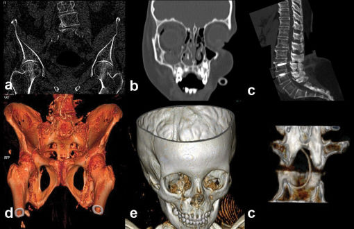
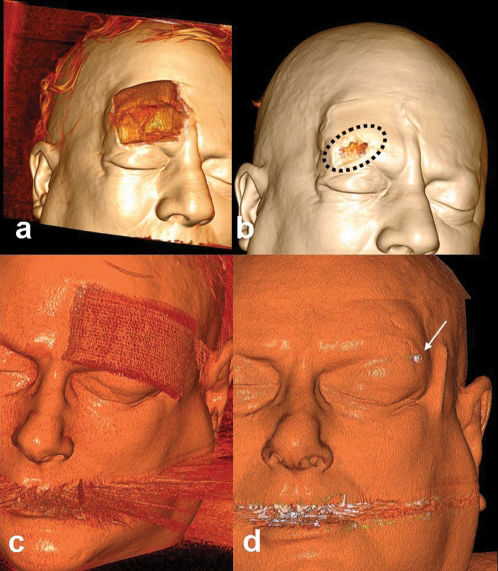
In 7 patients (one case with non-displaced femoral neck fracture, one case with a minimal impacted femoral neck fracture, 4 cases with orbital blow-out and/or rim fractures and a case with a foreign body in the spinal canal) were recorded as “2 or 3 points” in R-I, while R-II scores were “0 or 1 points” (Figure 1).
 A case with porotic femoral neck fracture. Although coronal bony reformat image (a) shows nonimpacted left femoral neck fracture line, it was not seen in the 3D image (d) in spite of appropriate settings. In another case with right orbital blow-out fracture (b, e) pathology was more demonstrative in the coronally oriented MPR images than in the 3D views. A foreign body (spinal anesthesia catheter) in the spinal canal was demonstrated easily by sagittal MPR image (e). It can be visualized by the 3D technique (f).")
In some conditions, MPR is superior to 3D images. a) A case with porotic femoral neck fracture. Although coronal bony reformat image (a) shows nonimpacted left femoral neck fracture line, it was not seen in the 3D image (d) in spite of appropriate settings. In another case with right orbital blow-out fracture (b, e) pathology was more demonstrative in the coronally oriented MPR images than in the 3D views. A foreign body (spinal anesthesia catheter) in the spinal canal was demonstrated easily by sagittal MPR image (e). It can be visualized by the 3D technique (f).
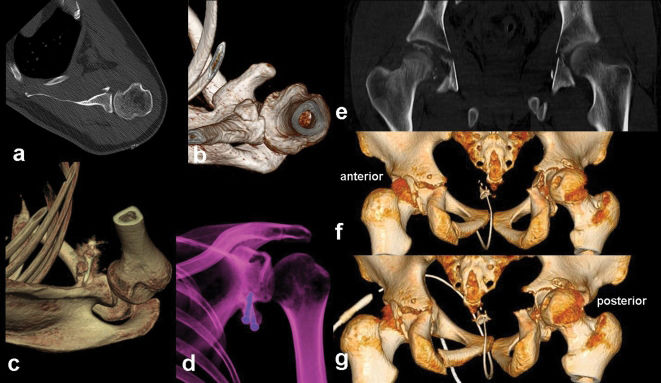
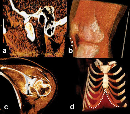
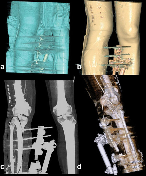
Otherwise, the differences recorded as important in R-II were related to 8 cases with upper extremity injuries, 9 cases with lower extremity injuries, and 5 cases with thoracic cage/pelvic cage/spinal injuries (Figure 2).
 and 3D image (b) show displaced osseous anterior glenoid rim. Six months after repairing with coracoid transfer, loosening of metallic screw is seen in the operation area,in VR-3D (c) and semitransparent 3D (d) images. In another case with severe pelvic trauma, although coronal plan image (e) shows derangement of the right hip, anterior (f) and posterior (g) 3D images show the displacement of the hip rather than just a fragmented fracture.3D images were, also, explanatory and drew attention to the left hip (with displaced fractures of acetabulary contours).")
3D image can reveal even minor osseous abnormalities. In a patient with Bankart lesion, axial (a) and 3D image (b) show displaced osseous anterior glenoid rim. Six months after repairing with coracoid transfer, loosening of metallic screw is seen in the operation area,in VR-3D (c) and semitransparent 3D (d) images. In another case with severe pelvic trauma, although coronal plan image (e) shows derangement of the right hip, anterior (f) and posterior (g) 3D images show the displacement of the hip rather than just a fragmented fracture.3D images were, also, explanatory and drew attention to the left hip (with displaced fractures of acetabulary contours).
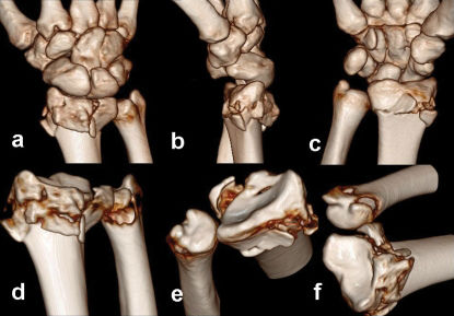
The R-II score was higher in the non-articular fractures of the extremities, with an average score of 2 points. On the other hand, in the articular-periarticular osseous injuries, R-II were assigned 3 points on average by more oriented images (Figure 3).
 with these systems in order to delineate intra-articular fracture lines.")
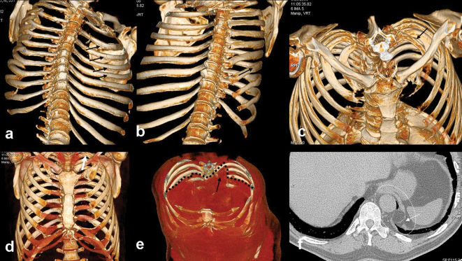
While the R-II data were determined to be in the more important category for the thoracic cage (at the 3 points level), more data were provided compared to R-I (unimportant category-weighted) with a 2 point average for the pelvic cage (Figure 4).
. a) 3D Endothoracic view image shows multiple rib fractures (arrows), b) although these are barely visible with external view 3D image (arrow). c, d) outlet view superiorly and front-view images are excellent to evaluate bony and osseous structure together. A left cervical rib variant is visible in two images (black arrow in c, white arrow in d). e) Coronal oblique 3D view shows the defect at the left medial diaphragmatic contours (dashed black line and arrow). f) The defect area is also visible with the axial conventional image (dashed ellipse and arrow).")
A case of thoracic cage injury (out-of-vehicle accident). a) 3D Endothoracic view image shows multiple rib fractures (arrows), b) although these are barely visible with external view 3D image (arrow). c, d) outlet view superiorly and front-view images are excellent to evaluate bony and osseous structure together. A left cervical rib variant is visible in two images (black arrow in c, white arrow in d). e) Coronal oblique 3D view shows the defect at the left medial diaphragmatic contours (dashed black line and arrow). f) The defect area is also visible with the axial conventional image (dashed ellipse and arrow).
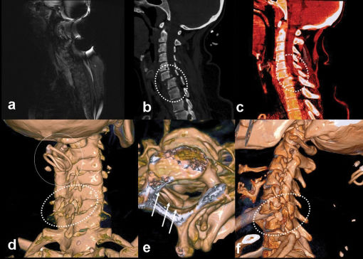
For the spinal column, R-I data were more significant, with 2 points in the definition of the anterior compartment configuration (listhesia, compression fracture detection and orientation to fracture configuration). Also, for intracanalicular pathologies (posterior elements or fragmentous displacements to the canalicular surface, foreign bodies and - despite not being included in the statistical evaluations - epidural soft tissue components) R-I was scored with 3 points compared the “1 or 2” points scores of R-II. However, R-II data were again more significant in the injury or extracanalicular displacement of the posterior elements of the osseous spinal column (Figure 5, Figure 6).
. a) MRI did not yield diagnostic data because of artifacts in the strictly immobilized patient. The case was referred to the MDCT unit. b) C5-C6 anthelistesis is obvious in sagittal reformatted image (dashed ellipse). c) Spinal epidural hematoma was seen at the listesis level, causing a decrease in the canal diameter (dashed ellipse). d) It is possible to see the source of the artifacts (hairgrip, circle in d). Also, the disorganized posterior elements were representing another injury side (dashed ellipse in d). It was not possible to see the grip with inspection because of the collar. It might have been dangerous for the patient to remove the collar. Otherwise, it may also be harmful to the patients or technicians if there is a probability of random movement of metallic materials in the MRI unit. e) Longitudinal view, it is possible to see the laminal depressions in the canal (arrows). f) In the left oblique view, we can see the listesis, posterior element fractures, and pars interarticularis dehiscence all together (dashed ellipse) in one image.")
A case of cervical trauma (in-vehicle accident). a) MRI did not yield diagnostic data because of artifacts in the strictly immobilized patient. The case was referred to the MDCT unit. b) C5-C6 anthelistesis is obvious in sagittal reformatted image (dashed ellipse). c) Spinal epidural hematoma was seen at the listesis level, causing a decrease in the canal diameter (dashed ellipse). d) It is possible to see the source of the artifacts (hairgrip, circle in d). Also, the disorganized posterior elements were representing another injury side (dashed ellipse in d). It was not possible to see the grip with inspection because of the collar. It might have been dangerous for the patient to remove the collar. Otherwise, it may also be harmful to the patients or technicians if there is a probability of random movement of metallic materials in the MRI unit. e) Longitudinal view, it is possible to see the laminal depressions in the canal (arrows). f) In the left oblique view, we can see the listesis, posterior element fractures, and pars interarticularis dehiscence all together (dashed ellipse) in one image.
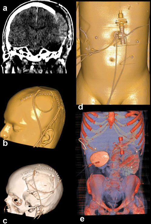
 Cerebral herniation from the defect in the left parietal area. b) All drainage tubes, catheters and the defect area can be seen in different 3D Windows (b, c). In the same patient it was also detected the abdominal catheters (drainage tubes, gastrostomy tube, d) and buried calvarium in the abdominal wall (e).")
Cranial trauma. a) Cerebral herniation from the defect in the left parietal area. b) All drainage tubes, catheters and the defect area can be seen in different 3D Windows (b, c). In the same patient it was also detected the abdominal catheters (drainage tubes, gastrostomy tube, d) and buried calvarium in the abdominal wall (e).
Also, in another two patients referred with polytrauma, R-II data, which were found to be more statistically significant, were scored with 3 points higher on average than R-I in the aspects of orientation, short processing and adaptation time (5 mins versus 11 mins) for acquiring critical information (Figure 6, Figure 7).
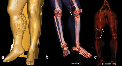
 The open and wide wound at the trauma site is visible. b) In the 3D CT-A image, the popliteal artery was interrupted suddenly because of penetrating vascular trauma. c) After removal of the bony structure, it was seen that the collateral supply (a variation) from the genicular branch was enabling the distal tissue to survive.")
Right cruris injury in a vehicle accident,. a) The open and wide wound at the trauma site is visible. b) In the 3D CT-A image, the popliteal artery was interrupted suddenly because of penetrating vascular trauma. c) After removal of the bony structure, it was seen that the collateral supply (a variation) from the genicular branch was enabling the distal tissue to survive.
The measured average score for R-I for all of the subjects was 1.25; while it was recorded as 1.99 for R-II. Thus, a statistically significant difference (p = 0.000005) was shown in the Chi-square test, which proved that findings described by the R-II method defined posttraumatic pathologies more efficiently. In the all evaluated data, it was seen that 3D scans were fast and more efficient in providing good orientation for clinicians.
DISCUSSIONTo our knowledge, this is the first article about the standardization of postprocessing operations in the literature in English. With this study, our aim was to display the usefulness and differences of both (MPR versus 3-D) modalities, with their advantages and disadvantages. In this way, we intended to make a first step towards the standardization of the postprocessing algorithm, at least for osseous trauma patients.
MDCT plays a major role in diagnostic workflow in the evaluation of patients with trauma.3,4
Traumatized patients usually have injuries in several anatomical regions or organs, and CT assessment of such patients should be systematic, complete, and accurate. Another key factor is the time required for radiological examination, which, because the chance of survival increases the sooner trauma care is initiated, must be as short as possible.3,5
The reliability and workflow of MDCT for emergency purposes have been supported by the results of several studies.5-9 MDCT scanners are widely used because they rapidly produce high-resolution images of large areas, offering short examination times for multiple body regions under emergency conditions.6-11 With new software programs and systems which have 64 or more detectors, 3D scanning and also processing time has been reduced significantly.4 Additionally, reduced radiation exposure rates have made the MDCT as preferred method in the trauma setting especially in unstable and uncooperative cases. Sometimes, it is possible to examine the affected area can be completed in subsecond time with new generation machines. So, it can exclude any requirement for sedation which may be used as a first line examination method especially in pediatric trauma cases.5,12 Seven pediatric cases in this study had been diagnosed directly with MDCT examination but without need for MRI or direct radiography correlation.
Orientation can be facilitated with MPR and 3D reconstruction in addition to the conventional axial images without changing routine MDCT examination protocols for trauma. Although there are many studies about the CT or MDCT protocols in trauma cases; there is no other record which emphasizes the standardization of the postprocessing algorithm or efficiency of 3-D images objectively.3,9,11 In this study, while high resolution axial plus MPR images may be enough, we answer the question as to whether or not the formation and evaluation of the 3D images is needed.
It is also a known fact that besides the difficulty of quick evaluation of a high number of axial images consecutively, there are also difficulties regarding time and cost in the storage and retrieval of this information when needed.13 Forming and storing 3D images may partially alleviate this problem. Likewise, another important but overlooked point is the opportunity for processing the same data to produce 3D images from remote computers. This makes virtual inspection by teleradiologists possible. Although transferring high resolution and numerous images consumes time, a small number of focused 3D images can be transferred in a short time.14,15
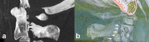
It must be remembered that images reconstructed in the bone window give higher contour resolution in the sectional images, whereas thin axial images reconstructed in soft tissue kernels should be used for 3D evaluation16 (Figure 8).
, it is ambiguous in 3D images which are constituted from the bony kernels (white arrows in b). Thin section reconstruction for 3D images had to be achieved technically by processing in the soft tissue kernels.")
In spite of the fracture line through the lamina of C2 vertebra in the thick MIP slab sagittal image (black arrows in a), it is ambiguous in 3D images which are constituted from the bony kernels (white arrows in b). Thin section reconstruction for 3D images had to be achieved technically by processing in the soft tissue kernels.
The average time needed for each case for R-I and R-II protocols was 15 minutes, and 11,5 minutes respectively. At emergency setting, the time spared with R-II protocol is critical for each patient. One of the facilities in the evaluation of 3D images is the ability to orient the reader's attention directly to the injury site by turning around the skeleton to reveal any defect 16,23 (Figure 14). In this way, it is possible to detect abnormalities easily in a short time.24,25 It is also is possible to reduce the artifacts or and to remove superposition (missed foreign bodies, pathological fractures, superposed implants or catheters) by this method.

Gunshots wound and fracture of the tibiofibular shaft. Fixation achieved in emergency to stabilize the fractures and to control the patient's hemodynamy. Immediately after the operation the right dorsalis pedis artery was nonpalpable with right ankle and foot pain. On CT angiography, it was seen in the gradually and virtually undressed images (from a to d) that the anterior tibial artery had been suddenly interrupted behind the fixator trace (consistent with occlusion). Comparing with image c, it is more visible in the 3D image shown in d (dashed ellipses). These series of images show the possibility of understanding complicated cases or artifactual findings with special removal techniques, or by changing window-color-transparency settings.
With R-I protocol eight extra unimportant findings were identified where as in R-II protocol 52 additional unimportant findings was found. In terms of important findings, R-I noted 6 and R-II recorded 23 important findings. In only 11 cases, both methods scored the same important findings.
R-I protocol was thought to be the appropriate protocol for the evalaution of basicranium, orbital rim (blow-out), temporal bone, spinal canal, vertebral body internal contour injuries and intra-articular fragments due to their complex anatomical structures and superpozitions. R-II protocol was used to evaluate facial bones, calvarium, ribs, the posterior elements of the spinal column, long bones and articular surface integrity because it provided quick and cumulative information. It is obvious that usage of improper modality in inappropriate conditions leads time consumption
In some conditions, one of these techniques may be mandatory due to different characteristics of patients. For example, non-displaced but minimally impacted porotic femoral neck fractures can only be identified by the evaluation of axial+3D images. In porotic patients, 3D images, even with suitable reconstruction, were not able to show the pathologies like fissures or nondisplaced fracture lines.
In this study, 3D images were examined by turning image fully around the vertical and horizontal axis (if needed in oblique positions) at least once. 3D image windows were produced from skin surface to the soft tissues at first, and then to the bony structure examined in more suitable colors. Because of the scope of the study, we emphasized the efficiency of the 3D images in the acute post-traumatic osseous changes. However, superficial anatomy, tendons, periarticular ligaments, muscles and meniscal structures can be seen clearly with the colored 3D-VR images without administering any contrast agent.17,18 Thus, this method will be crucial in cases where MRI examination is contradicted10 (Figure 9).
 and muscles (supra and infraspinatus, dashed lines in c) in thick slab colored VR images. Also with 3D images, we can see tendons (patellary tendon, small arrows in b) and cartilage (costal arch, dashed lines in d) structures.")
Extraosseous findings in some cases who were not convenient for MRI. It is possible to see the menisci (temporomandibular joint disc, dashed rectangular in a) and muscles (supra and infraspinatus, dashed lines in c) in thick slab colored VR images. Also with 3D images, we can see tendons (patellary tendon, small arrows in b) and cartilage (costal arch, dashed lines in d) structures.
Patients with huge defects in their skin or other soft tissues but without any osseous injury being reported as normal with conventional axial or MPR images because of obscurence in sectional slices. But this may lower the confidence of readers. However, those injuries can be determined easily by 3D application examination. With the pointing out of the primary injuried sites, 3D application is an interesting tool which can be equal to diffusion weighted imaging considering that it has an effect that accelerates diagnosis.
In our cases, MPR images presented more useful data especially in spinal column injuries, and in intracanalicular pathologies (posterior vertebral contour instability, epidural lesions, disc pathologies, non-osseous pathologies, and foreign bodies). This is probably related to the curved spinal column anatomy which prevents optimal virtual 3D evaluation through the spinal canal. But in some circumstances (such as with foreign bodies) the evaluation of intracanaliculary structure with 3D images may provide clearer and sufficient information in the detection of pathologies, and 3D method may yield good anatomical orientation to clinicians (19-22) (Figure 7).
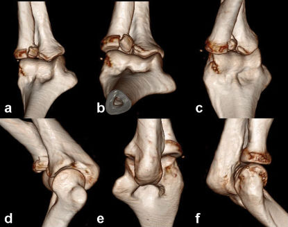
Articular and periarticular traumas can be evaluated confidently by means of different view angles in 3D images. The affected joint surfaces can also be evaluated by virtual-3D exarticulations from different angles to view the articular surface integrity (Figure 10). Foreign bodies, fixation devices, plaster casts and splints which may hamper the image quality also can be virtually removed.22 In pediatric patients, evaluation of the epiphyseal lines may be impossible with axial images due to misleading variations. Also, it may be difficult to reveal the fracture orientation only with MPR sections. All the epiphyseal lines can be easily evaluated by the 3D images, so that injury characterization (according to Salter-Harris categorization) can also be made confidently21 (Figure 11).

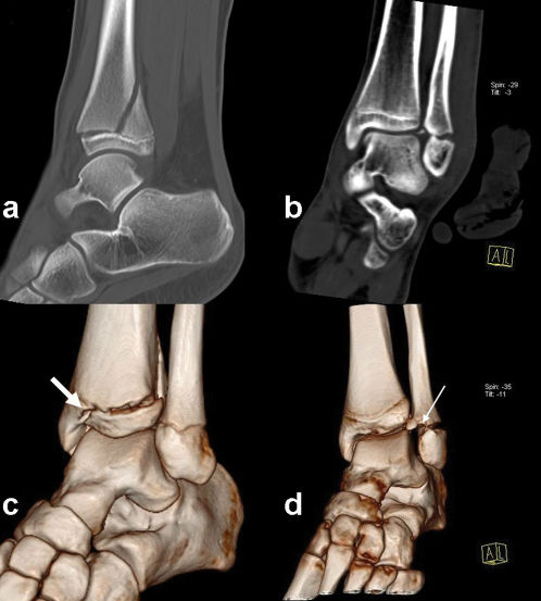
 through the physis extending up into the metaphysis (Type II) was corrected as type IV by 3D image (thick arrow c). In another case with fibulary malleolar fracture (b), classification also was corrected by 3D imaging findings (thick arrow in d) (conversion of type IV to type II).")
It is very useful to perform the 3D data on the Salter Harris criteria on the young patients with epiphyseal trauma. A fracture line (a) through the physis extending up into the metaphysis (Type II) was corrected as type IV by 3D image (thick arrow c). In another case with fibulary malleolar fracture (b), classification also was corrected by 3D imaging findings (thick arrow in d) (conversion of type IV to type II).
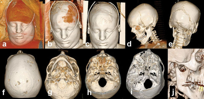
Due to the high resolution, it is possible to differentiate avulsion nonavulsion, separated fragments and ossified components. Osseous contours must be examined clearly in the 3D images especially confirming the conventional axial slices. In all cases, especially in maxillofacial traumas, whole images formed from the skin to the bone surface should be examined step by step to to assess the primary injury site (Figure 12, Figure 13).
 to (j) to search all compartments of the examined area. In this case, it was possible to evaluate the soft tissues of the face (a, b, c) including superposed medical materials, and bony surfaces from different views (d, e, f). Basicranium and foramen magnum were also clarified by examining from different view angles, and the zoom-pan function can be directed to an arbitrarily chosen area or to a previously intended region (g, h, i).")
A case with head trauma admitted to the emergency service. The 3D images from skin to bone begin from neutral position and are then rotationally arranged from (a) to (j) to search all compartments of the examined area. In this case, it was possible to evaluate the soft tissues of the face (a, b, c) including superposed medical materials, and bony surfaces from different views (d, e, f). Basicranium and foramen magnum were also clarified by examining from different view angles, and the zoom-pan function can be directed to an arbitrarily chosen area or to a previously intended region (g, h, i).
 the wound was unsutured (mistakenly) and in the other case (c, d) a millimetric shining object was seen (as a foreign body – a rounded pebble, after reintervention). It is possible to investigate the detail and deepen the examination boundaries beyond the images.")
Two cases with similar trauma type in the emergency service. First intervention had been performed in another center, which referred them for cranial CT to exclude hemorrhage. It was only possible to obtain high quality 3D images by processing this nonfocused section. In one case (a, b) the wound was unsutured (mistakenly) and in the other case (c, d) a millimetric shining object was seen (as a foreign body – a rounded pebble, after reintervention). It is possible to investigate the detail and deepen the examination boundaries beyond the images.
Considering all the points in Table I, the measured average score for R-I was 1.25; while it was recorded as 1.99 for R-II. And also to the all evaluated data, it was seen that 3D scans were fast and more efficient in providing good orientation for clinicians.
In summary, 3D images must be adjusted from the skin to the bony surfaces by changing the window settings. The whole image should be examined by being turned fully at least once around the axial and coronal planes. If necessary, artifact-producing implants, splints or fixators can be extracted in the virtual settings. Porotic bones, deep structures (temporal, facial, basicranial bony structure), or the spinal column should not be evaluated by 3D images only. These areas must be examined mainly with MPR images because of their superiority to 3D imaging in these regions. Injured articular surface integrity can be examined with virtually exarticulated images. It can also be said that examining the ligamentous or meniscal anatomy with coloured VR-MPR images may provide more detailed information (especially in patients whom MRI contrendicated for) than 3D imaging.
In conclusion, imaging the injured skeleton in a trauma patient can be evaluated in twelve minutes with dual source MDCT sysem. It must be rotated by it self in whole axes at least once. Virtual inspection, virtual exarticulation is possible with 3D images. 3D-CT imaging is a perfect method for evaluating unstable or MRI-incompatible cases, and does not need direct graphy correlation. Because of these numerous utilities, 3D images must be created and evaluated for all trauma cases.