


The global positioning system (GPS) is an important research topic to solve outdoor positioning problems, but GPS is unable to locate objects accurately and precisely indoors. Some available systems apply ultrasound or optical tracking. This paper presents an efficient proportional-integral-derivative (PID) controller with curve fitting model for mobile robot localization and position estimation which adopts passive radio frequency identification (RFID) tags in a space. This scheme is based on a mobile robot carries an RFID reader module which reads the installed low-cost passive tags under the floor in a grid-like pattern. The PID controllers increase the efficiency of captured RFID tags and the curve fitting model is used to systematically identify the revolutions per minute (RPM) of the motor. We control and monitor the position of the robot from a remote location through a mobile phone via Wi-Fi and Bluetooth network. Experiment results present that the number of captured RFID tags of our proposed scheme outperforms that of the previous scheme.
With advanced technologies, the robot design and research is the most challenging field of robotics. The robot technologies have been widely extended to various applications, such as factory applications, industrial applications and recreation. Since the more mobile robot are becoming autonomous systems, the navigation and positioning techniques of mobile robot are the fundamental robotics problems. The mobile robot would be easier to execute commands safely when a mobile robot is able to move based on accurate estimates of its location and direction. Thus, the position of the robot becomes a key issue for the navigation of mobile robot. The reliable control procedure and the accurate of the location perception are taken into account.
An example of the industrial application is the tracking of autonomous systems. The location module provides the application with the location of the object, such as a user or a robot. In such systems, the location module is the core component. Positioning algorithms using dead reckoning (DR) [1] are widely used. In navigation, the process of DR is calculating the current position using a previously determined position, and advancing that position based upon known or estimated speeds over elapsed time. A disadvantage of dead reckoning is that since new values are calculated solely from previous values, any error and uncertainties in the process are cumulative with time. DR has a major drawback: displacement and azimuth because the time integral will result in error accumulation. Several researches have combined more sensors [2], such as cameras, sonar, laser range finders and global positioning system (GPS) [3] in recent years to increase the accuracy of position.
GPS is widely used in outdoor positioning systems. It can track moving objects in outdoor environment. Although GPS is one of the most famous positioning systems in outdoor environments, the accuracy, precision, synchronization, and penetration of GPS are insufficient to meet the requirements of indoor location-aware applications. It is necessary that an efficient location system can trace mobile robot‘s movements in indoor environment. We use curve fitting model to measure the revolutions per minute (RPM) of a motor and obtain a mathematical model.
This paper presents a method for the position of a mobile robot which uses PID [4-6] controllers and curve fitting model [7]. The antenna detects passive RFID tags [8] were laid on the floor in a grid-like pattern. The mobile robot is equipped with a RFID reader which detects passive RFID tags to locate mobile robots and solves the problem of robot tracking in indoor environments. In order to measure the positioning system and compare our proposed scheme with other alternatives, we exposed a set of aspects to view. We also conducted a location awareness proof concept test to analysis the feasibility of our proposed method.
2Location system technologies and applicationsIn this section, we list the most representative indoor positioning method. We evaluate and compare the performance of our proposed system in terms of accuracy, installation, lifetime and other standards under different conditions:
- a.
Power: Low power consumption and energy efficiency are considered the most important targets.
- b.
Precision: By precision as the percentage of time to the location system provides the given accuracy.
- c.
Accuracy: We define accuracy we mean how much the estimated position is deviated from the real position.
- d.
Wearable and expectation of life: A desirable feature is the ability to be wearable, problems caused by failure to reduce the increase in maintenance costs.
- e.
Adaptability and scalability: When deployed to a given building, indoor location systems should be adaptable to changes, and flexible enough to be able to expand to other buildings without being adversely affected.
- f.
Environmental factors: Factors such as the building materials, location of tags, and the body‘s location should not affect the performance of the system.
- g.
Responsiveness/delay: Location systems should provide real-time position values.
- h.
Cost: The system must embrace the direct and indirect costs of deploying a location system, for example; infrastructure, maintenance, installation and setup costs.
Wi-Fi system accuracy is limited to within about 3-5 m, and is the most popular technology used to connect to the Internet or any other network. One of the advantages of using this system is the existing IEEE 802.11 infrastructure, resulting in reduced cost. The basic principles used by most systems using Wi-Fi location are received signal strength indicator (RSSI) and time difference of arrival (TDOA). Thus, using received signal strength to find the distance from the various tags, the RSSI value from an access point to the tag is converted to distance. However, minor network changes may require the re-adjustment of the entire location system. Some examples are: [9-10].
2.2Bluetooth systems (IEEE 802.15)The sensor accuracy of Bluetooth system is about 2 -15 m, Bluetooth is a wireless network standard designed for communication and low power consumption with in limited network. One of the most valuable advantages of Bluetooth technology is variable reading distance. It is capable for 1/10/50m reading range, being proximity or suitable for locating objects. Moreover, the cost of implementation on a small scale is relatively cheap.
However, to development for large scale is expensive. Jump frequency or channel for communication between devices can take up to 10s. To reduce this time you can use the inquiry phase only, but you cannot use RSSI or link quality parameters for deducing location resulting in a less accurate measurement. Besides, it can locate only 7 objects in an area of 3m, the reason is about the master connections capabilities. Some examples are given in [11].
2.3Infrared radiation systemsInfrared radiation (IR) is some of the easiest technologies to implement. IR accuracy is about 5 - 10 m. Although the system seems result in cheap, compact and low power consumption, but it also have disadvantages: they are sensitive to sunlight, must be in the line-of-sight and the costs of installation are high at large scale.
Unlike RF carrier frequencies such as those present in the mobility, infrared technology is a safe technology. Infrared systems use only optical spectrum to achieve communication and does not penetrate into living tissue. Some examples of the location systems using infrared technology can be found in [12].
2.4Ultrasound systemsUltrasound accuracy is about 5 - 10 m. It is sound that has a higher frequency than the frequency upper limit of human hearing. Some advantages of adopting this technology are the simplicity and inexpensiveness of the devices, but the environmental sounds can have effects on the health of people, these limits vary from person to person and are about 20 kHz in young healthy adults, and in order to be located, transmitter and receiver have to be in the line-of-sight. Some examples of this technology are given in [13].
2.5Inertial navigation systems and sensorsInertial navigation system (INS) accuracy is about 300 m. INS is a navigation aid, that uses a computer, motion sensors and rotation sensors to continuously calculate via dead reckoning the position, physical device that detects, or senses, a signal or physical condition [14]. Some examples are accelerometers, barometric pressure or altimeter, pressure and light.
It is used on vehicles such as submarines, aircraft, ships, guided missiles, and spacecraft. Other terms used to refer to inertial navigation systems or closely related devices include inertial guidance system, inertial reference platform, inertial instrument, inertial measurement unit and many other variations. Besides, it is really important to point out that these systems are not very appropriate for large systems.
2.6Radio frequency identification systemsRadio frequency identification (RFID) is a new technology. One advantage of this technology is the ability to work under adverse environmental conditions, unlike ultrasound systems, which have problems with noise, or IR, which has problems with light. RFID systems consist of a tag, a reader and a software program to manage the system.
RFID is also useful in mobile robotics as a substitute for other forms of landmark detection as a basis for navigation [15-17]. RFID systems have a fast response time, are cost-effective, have a significant lifetime and are low maintenance; these are some important benefits arising from the fact that these systems do not need batteries.
3A PID positioning controller with a curve fitting model based on passive RFID technologyRFID has been used for the positioning, tracking and navigation of mobile robots. In this paper, we propose a new controller to evaluate the location system. Furthermore, the system goal is to trace the robot movements within a specified area.
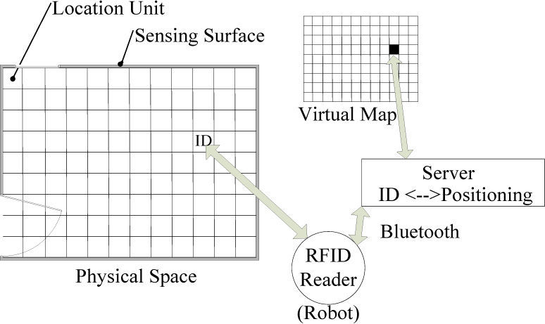
Tesonero [18] et al. assigned the identification (ID) to a physical surface for obtaining the location unit. To complete this task, we used passive RFID tags. A RFID tag has a unique ID, which represents a location unit. A grid of tags represents a sensing surface, as shown in Figure 1. A passive RFID reader which is attached to the object that this system aims to locate on the surface is used to retrieve tag information, and a mobile client can monitor and control the position of the robot. The server can control and monitor the position of the robot from a remote location through a Bluetooth network. The system is shown in Figure 1.
3.1The robot system architecture
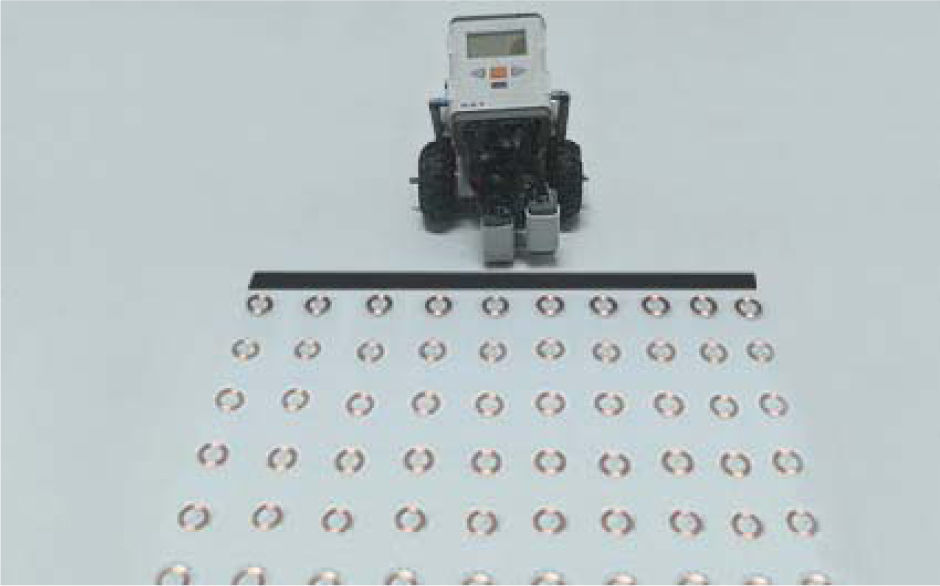
The robot is a Lego Mindstorms robot with a 32-bit Arm AT91SAM7S256 microcontroller as its internal CPU, and supports a Bluetooth connection. In addition, the Lego robot is equipped with a light sensor, a grid of passive RFID tags and a passive 125 kHz RFID reader, as shown in Figure 2. We built a three-wheel Lego robot, and the reader is pointed towards the floor.

The positioning manager maintains the relationship between location units and physical space locations in order to locate entities within the spaces. The architecture of the system software is based on a Client-Server structure. The server displays the physical position information of the robot to the user. There are three necessary elements for this system: the RFID reader, Bluetooth and Wi-Fi networks. The information of the passive RFID tag is read by the RFID reader from the sensing surface, and the information can be sent to the server via a Bluetooth network process, as can the communication of the ID to the server for mapping that ID to the physical surface that it represents.
The mobile client that monitors and controls the robot through the server has two necessary elements: the browser and a wireless connection device. To allow communication between the robot and the server, this system uses a Bluetooth connection, and the mobile client uses a Wi-Fi connection to monitor and control the robot via the server. The server has four main elements:
- I.
A Bluetooth connection system: Receives the entity location IDs from the robot.
- II.
Physical to virtual location mapping: Matches an ID to a virtual map position.
- III.
Web control system: Shows the entity locations for the client.
- IV.
The map presentation screen: Shows the entity locations to the end user.
When a location unit is retrieved from the positioning manager database using the ID received by the client, mapping the ID to an indoor location is one of the most important challenges in the application modeling.
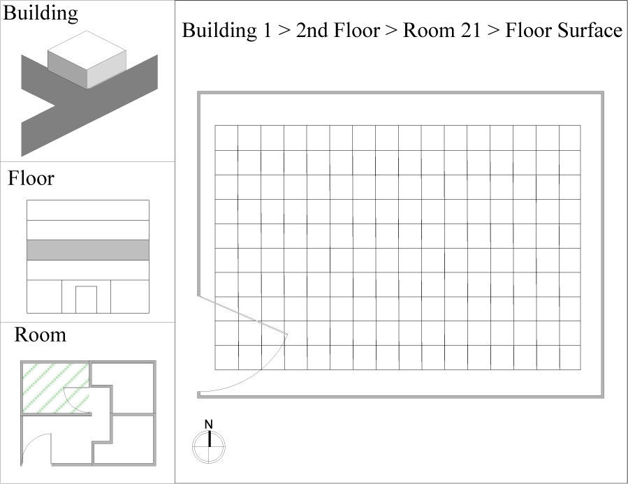
3.2Sensing surfacesA means of mapping the ID to an indoor location is the first important issue concerning the application modeling. The process starts when a location unit is retrieved from the Location Manager database using the ID received by the client. Figure 3 shows that the location unit may represent a wall or a floor associated with a sensing surface. The sensing surface belongs to a room which is related to a building floor. From the ID, we can identify the room, and know to which floor and building the ID belongs. This system has the full location path of the Lego robot we want to locate. To put it simply, this application has two working modes: exploring and tracking. The exploring mode allows users to monitor the Lego robot‘s position from the presentation screen, and the tracking mode allows users to "follow" the Lego robot through the building, as shown in Figure 3. In order to reduce the number of RFID tags, we divide the room into two grid tags, with a black line between different grid tags, as shown in Figure 3. The Lego robot can track the black line by a light sensor from one grid tag to the other.

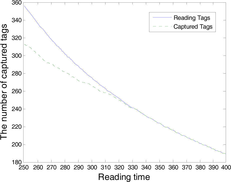
Two important configuration parameters are required for the reasonable performance of a location system in a RFID grid tag system: the reading and timeout times. In order to obtain a reasonable response time, we set the experiment parameters in the following scenario:
- 1).
RFID tag put on the reader.
- 2).
250 ms to 400 ms reading time.
- 3).
60 seconds for every cycle performed.
- 4).
Ten measurements were performed.
Figure 4 shows the experiment measurements. We find that the number of read tags and captured tags are the same over a reading time of 330 ms. Therefore, we set the reading time (time interval to perform readings) to 330 ms, and the reader timeout (time the reader has to recognize a tag) to 100 ms. The tracking speed of the system is 3.03 tags/s, and 25mm/tag×3.03 tags/s≅75mm/s.
3.3Curve fitting
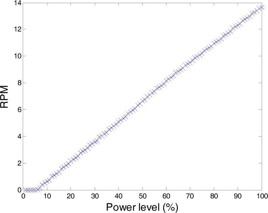
The curve fitting scheme is used in such diverse fields as economics, electrical engineering or traffic analysis. We discuss the applications in motor RPM, and measure the RPM of a motor over power level, as shown in Figure 5.

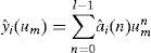
Assume that y¡(um) denotes the surveyed i th RPM in power level um. To simplify the following description, let Qi, denote point (um,yi(um)). We construct an l−1 order polynomial l−1 by interpolating R points, {Qi}i=0P-1 for the RPM, and the resulting polynomial is given by
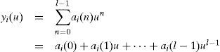
where {ai,(n)} are unknown coefficients. Because yi (um) for m=0, 1,..., R−1, we have the following matrix-form equality:
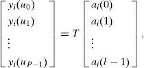
where
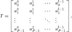
Furthermore, the vector on the left hand side of Eq. (2) presents the tracks of the received data during the period from u0 to uP−1. With the least square minimization, the I unknown coefficients is given by
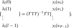
Therefore, the estimated RPM of motor can be smoothed according to Eq. (4):
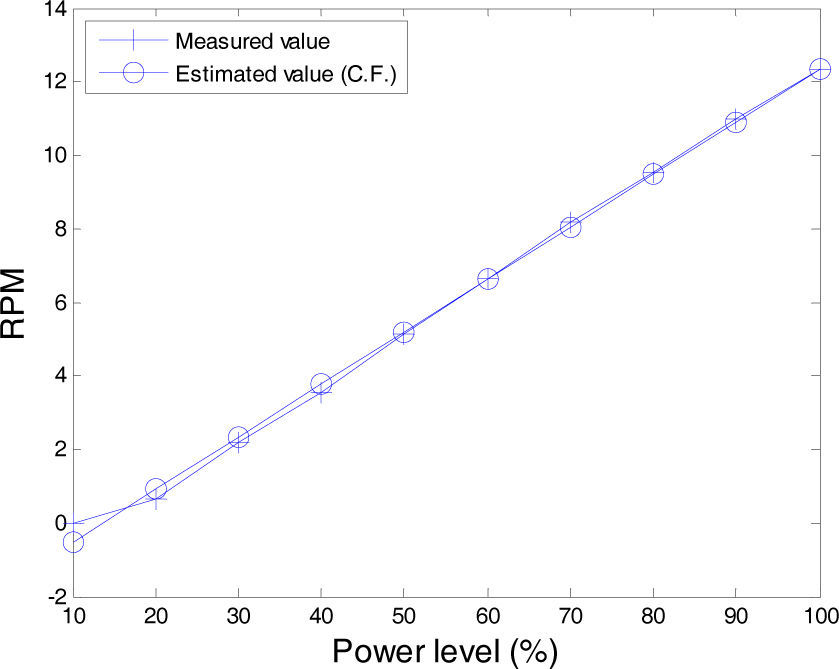
The experiment results show ten measured values measured by different power level. The ten measured values y(t) are 0, 0.6333, 2.1666, 3.5666, 5.1166, 6.6333, 8.1666, 9.5333, 10.9666, and 12.3166. From Eq. (5), we obtain the estimated RPM of the motor, which is expressed as

From Eq. (6), the curve fitting values are: -0. 5082, 0.9180, 2.3443, 3.7705, 5.1968, 6.6230, 8.0493, 9.4755, 10.9018, and 12.3281, as shown in Figure 6. The mean-square error (MSE) is calculated as the accuracy index reference in the following:

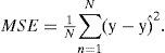
From Eq. (7), the MSE value is 0.4405.
3.4PID controllerIn this paper, we proposed an efficient location system to evaluate, and applied it to solve the robot tracking problem. The goal of the system is to trace the robot‘s movements within a specified area.
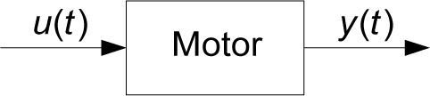
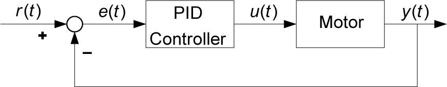
In Figure 7, Tesonero [18] et al. proposed the open loop controller system which has no feedback and requires the input to return to zero before the output will return to zero. In this paper, we employed a typically PID controller, as shown in Figure 8. The mathematical description of the PID controller is composed of the following three parts: Kp is the gain for the proportional term, Kd is the gain for the derivative term and Kj, is the gain for the integral term. The analog PID control algorithm can be represented by the following equation:


where y(t) denotes the measured RPM of the motor, u(t) denotes the control output of the PID controller and r(t) is the target RPM value. The traditional expressions for PID controllers can be described by their transfer functions relating error e(t)=r(t)−y(t). The error signal e(t) is used to create the proportional, integral, and derivative actions, with the resulting signals weighted and integrated to form the control signal u(t) applied to the plant model.
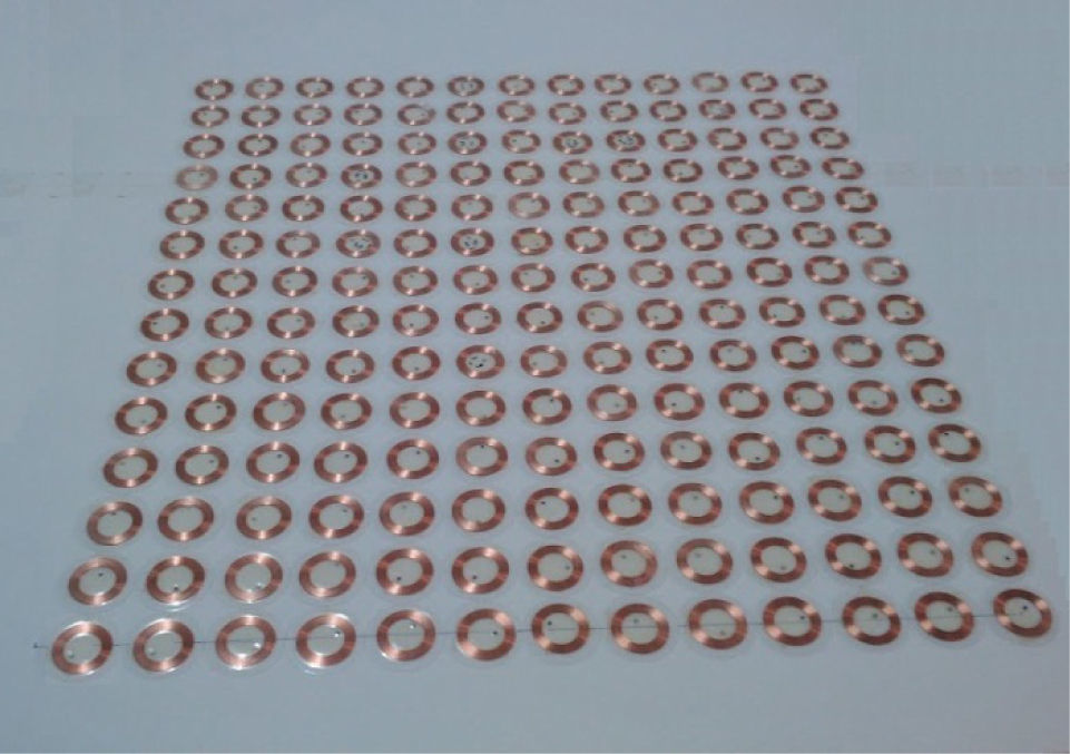
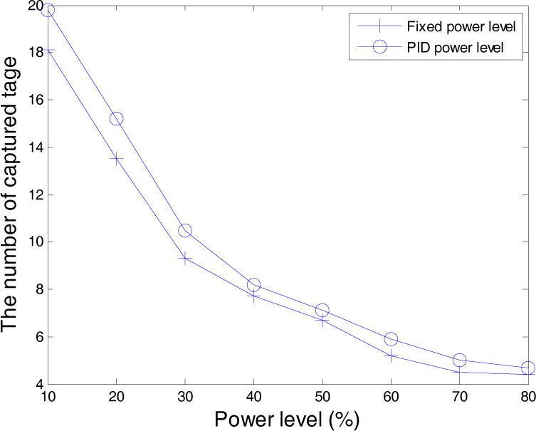
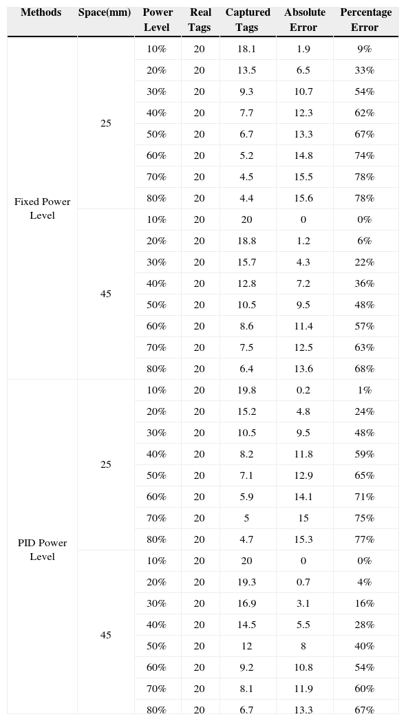
4Experiment resultsIn Figure 9, the environment is a 495mm×945mm indoor field, with the 100 passive RFID tags deployed with a spacing of 25 and 45mm. There are no obstacles on the floor. Table 1 gives the experiment measurements. We experiment the fixed power level method of reading efficiency compared with the PID power level method, our proposed PID method is compared with similar RFID-based studies that use the fixed power level method. As shown in Figure 10, power level is 6 with a tag spacing of 25mm, the number of captured RFID tags for the fixed power level method is 9.3, whereas for our proposed PID controller method the number of captured tags is 10.3, efficiency increase 10%. Therefore, the number of captured RFID tags using our proposed method is higher than that of the fixed power level method.

Tracking error calculation.
| Methods | Space(mm) | Power Level | Real Tags | Captured Tags | Absolute Error | Percentage Error |
|---|---|---|---|---|---|---|
| Fixed Power Level | 25 | 10% | 20 | 18.1 | 1.9 | 9% |
| 20% | 20 | 13.5 | 6.5 | 33% | ||
| 30% | 20 | 9.3 | 10.7 | 54% | ||
| 40% | 20 | 7.7 | 12.3 | 62% | ||
| 50% | 20 | 6.7 | 13.3 | 67% | ||
| 60% | 20 | 5.2 | 14.8 | 74% | ||
| 70% | 20 | 4.5 | 15.5 | 78% | ||
| 80% | 20 | 4.4 | 15.6 | 78% | ||
| 45 | 10% | 20 | 20 | 0 | 0% | |
| 20% | 20 | 18.8 | 1.2 | 6% | ||
| 30% | 20 | 15.7 | 4.3 | 22% | ||
| 40% | 20 | 12.8 | 7.2 | 36% | ||
| 50% | 20 | 10.5 | 9.5 | 48% | ||
| 60% | 20 | 8.6 | 11.4 | 57% | ||
| 70% | 20 | 7.5 | 12.5 | 63% | ||
| 80% | 20 | 6.4 | 13.6 | 68% | ||
| PID Power Level | 25 | 10% | 20 | 19.8 | 0.2 | 1% |
| 20% | 20 | 15.2 | 4.8 | 24% | ||
| 30% | 20 | 10.5 | 9.5 | 48% | ||
| 40% | 20 | 8.2 | 11.8 | 59% | ||
| 50% | 20 | 7.1 | 12.9 | 65% | ||
| 60% | 20 | 5.9 | 14.1 | 71% | ||
| 70% | 20 | 5 | 15 | 75% | ||
| 80% | 20 | 4.7 | 15.3 | 77% | ||
| 45 | 10% | 20 | 20 | 0 | 0% | |
| 20% | 20 | 19.3 | 0.7 | 4% | ||
| 30% | 20 | 16.9 | 3.1 | 16% | ||
| 40% | 20 | 14.5 | 5.5 | 28% | ||
| 50% | 20 | 12 | 8 | 40% | ||
| 60% | 20 | 9.2 | 10.8 | 54% | ||
| 70% | 20 | 8.1 | 11.9 | 60% | ||
| 80% | 20 | 6.7 | 13.3 | 67% |

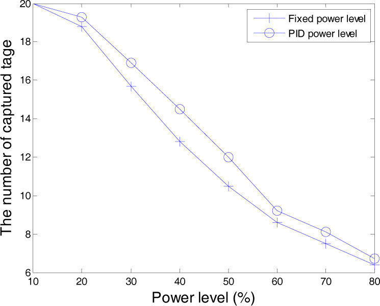
As illustrated in Figure 11, with a power level is 6 and 45mm spacing, the number of captured RFID tags for the fixed power level method is 15.7, whereas with our proposed PID controller method it is 16.9, efficiency increase 7%. Therefore, the number of captured RFID tags in our proposed method is also higher than that of the fixed power level method.

When the power level is 4 and tag space is 25mm, average reading efficiency of the fixed power level method is 6.7, whereas for the PID power level method, average read efficiency is 7.1, 5% increase in efficiency. When the power level is between 4 and 6, the PID power level method with 25mm spacing performs better than the fixed power level method.
Experiment results show that the 45mm tag spacing is apparently better than 25mm for average, and the number of captured tags of our PID power level method is larger than the fixed power level method. Table 1 also shows that the performance of the fixed power level method is larger than our PID power level method in terms of absolute error and percentage error.
5ConclusionsThis paper proposes an RFID-based location system using PID controllers that is used to track a Lego robot in indoor spaces. With this approach, we provide a solution to the problem of indoor localization of people or objects.
The system is based on sensing the surfaces and entities to be located. Communication with the entity via a location manager of the system employs Bluetooth. The location manager is in charge of mapping the tag ID read by the RFID reader, and shows locations on the tracking map. An RFID reader is attached to the entity to read RFID tags that are part of the sensing surface. The RFID tags can be identified robustly and reliably despite any covers, jitter, dirt, wear or vibration. We conclude that an RFID-tagged-room is a feasible option for real life applications. We evaluated our system, and demonstrated that it is highly accurate and precise by comparing its performance to other alternative systems. As a result of this evaluation, we believe that the accuracy could be further improved by using ultrasound systems, which are, however, more expensive in large deployments and are affected by noise. Curve fitting is the process of constructing a curve that has the best fit to a series of data points, possibly subject to constraints. The curve fitting scheme is used in such diverse fields as economics, electrical engineering or traffic analysis, we use curve fitting to estimate each RPM value at different power levels. We used PID power level to control the Lego robot. Compared with fixed power level methods, our system has a more stable speed, and a better reading performance. We did not spend too much time, compared with traditional methods. In engineering practice, the most widely used regulator control for proportional plus integral and plus derivative control, referred to as PID control, is known as a PID controller. The PID controller, since it was first used nearly 60 years ago, with its simple structure, good stability, reliability and easy adjustment, has become a major reliable industrial control tool.
AcknowledgementsThis work was supported in part by the National Science Council (NSC) of Republic of China under grant No. NSC 101-2221-E-025-006.