


In this paper, a rotary electromagnetic microgenerator is analyzed, designed and built. This microgenerator can convert human motions to electrical energy. The small size and use of a pendulum mechanism without gear are two main characteristics of the designed microgenerator. The generator can detect small vibrations and produce electrical energy. The performance of this microgenerator is evaluated by being installed peak-to-peak during normal walking. Also, the maximum harvested electrical energy during normal walking is around 416.6μW. This power is sufficient for many applications.
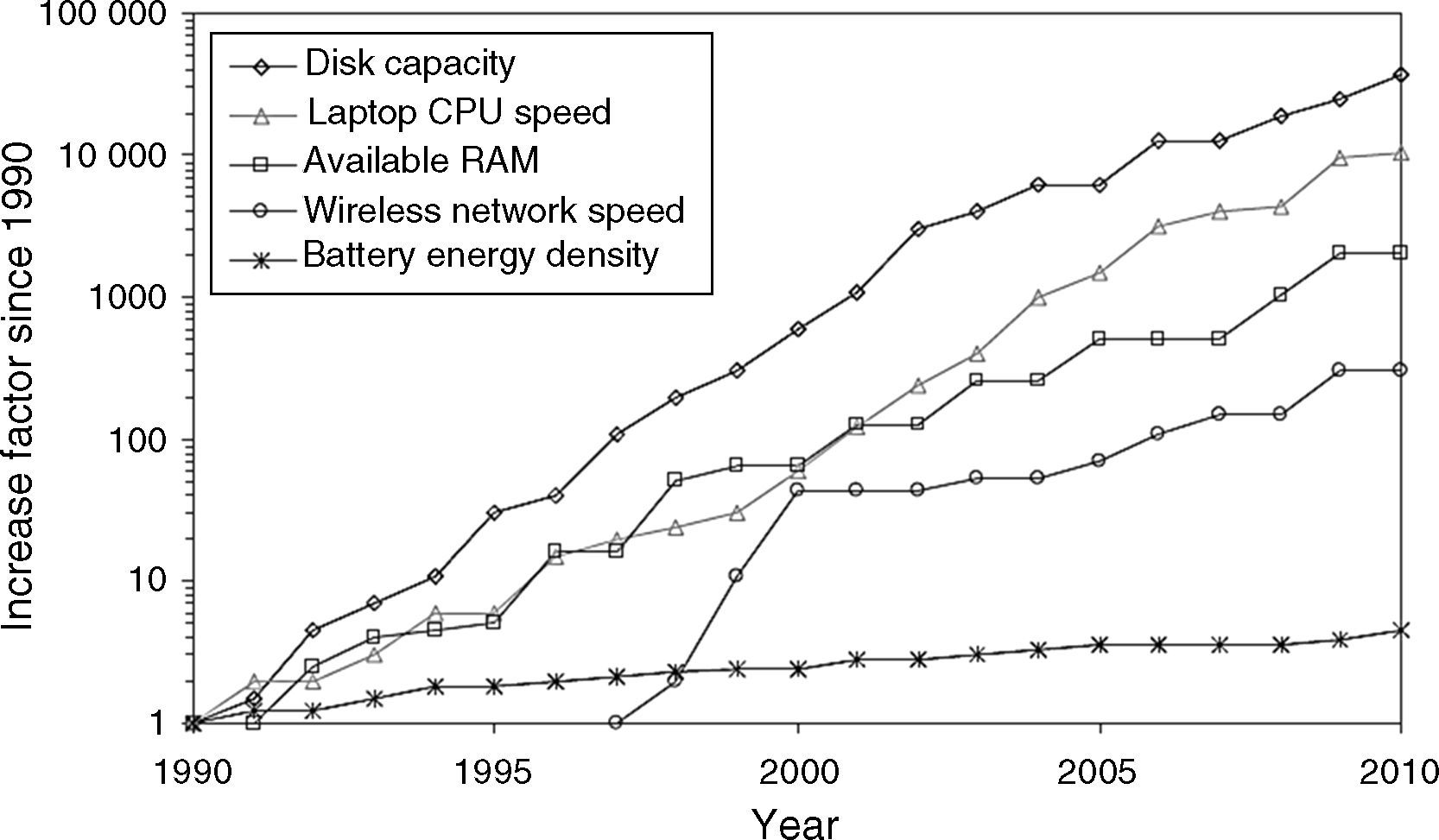
Computer technology has progressed quickly over the last two decades as shown in Figure 1; however, it is also clear that battery technology has not kept the same speed. Batteries, although the capacity of batteries has increased over these years, development of portable electronics seems to have slow down to reach a wider adoption. For example, the cost of a battery replacement prohibits a wider use of wireless sensor networks. As a result, other energy sources are needed to cover the demands of new electronic applications. Energy harvesting is an option to solve this problem.
.")
Improvements in portable computing from 1990 to 2010. Wireless connectivity only considers the IEEE 802.11 standard released in 1997. Partial data from specialized computer magazines (Starner & Paradiso, 2004).
Figure 1 shows the increase in the performance for different technologies compared to those available in 1990. For example, disk capacity has increased by a factor of 10,000 between 1990 and 2010, whereas battery energy density has increased only 5× (Collado & Georgiadis, 2013; Starner & Paradiso, 2004; Vaisband, Saadat, & Murmann, 2015).
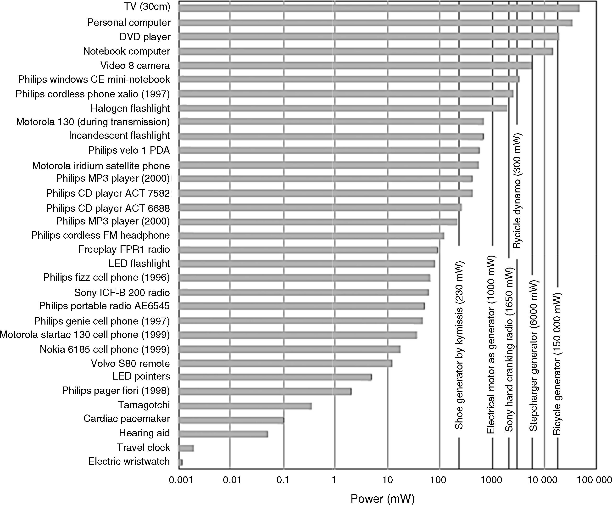
Moreover, energy sources other than batteries exist with even higher power densities, but most of them are designed for large systems and/or require some kind of fuel to operate. The human body is also an alternative energy source that can provide power densities around 1W/kg. Because of the decrease in the power consumption of electronic devices, the available power density levels of 1W/kg are an interesting option for low-power devices. Since power is generated by body motions, the devices that can directly be beneficial for this approach are biomedical and electronic devices (wearable or surgically implantable). Figure 2 highlights the power budget for some electronic applications within the generation range of the human body. For example, using the previous reference of 1W/kg, only a few miniature low-power devices (such as hearing aids, pacemakers, watches, and some consumer devices) can directly use the human energy harvesting approach. Nevertheless, larger generators can produce higher power outputs. Regarding the reference of 1W/kg, small generators with a volume of 10cm3 could produce up to 10mW. According to Figure 2, 10mW can be used to power some communication devices and remote controls. Taking as a reference the shoe-powered generator presented by Leonov (2013) with a power generation over 0.2W, power for some cell phones and radios can be supplied by human energy harvesting.

Comparison of power consumption against power generation for some electronic devices.
Figure 2 shows the power consumptions of different electronic devices ranging from medical devices to consumer applications (power consumption from around one microwatt up to several watts). This figure also presents the power output of an energy harvester (a shoe-powered generator) and some human-operated generators for comparison purposes. Even supposing that human microgenerators do not have a power output high enough for some electronic devices (such as laptops), they can produce a lower power output, for low-power electronic applications, including some medical devices. Thus, it is clear that human energy harvesting is suitable for biomedical applications and other low-power devices (Chen & Fan, 2015; Peng, Tang, Yang, & Heo, 2014).
Based on the above discussion, the design of a rotary microgenerator is described in this paper. This microgenerator can convert human motions to electrical energy. The small size and use of a pendulum mechanism without gear are the two main characteristics of the designed microgenerator. The generator can detect small vibrations and produce electrical energy.
This paper is organized as follows. Section 2 presents a background of the harvesting energy and its purposes. In Section 3, the mechanism of energy harvesting from body motions and its relations are described. The design process of the microgenerator and its relations are presented in Section 4. In Section 5, the implementation process of the microgenerator and several experimental results related to the microgenerator are explained. Finally, in the last section, a conclusion of the design process and the experimental tests are presented.
2Energy harvesting backgroundEnergy harvesting is a research subject that is gaining relevance for powering electronic devices because of an almost infinite life-time potential (Levron, Shmilovitz, & Martinez-Salamero, 2011; Ylli et al., 2015). Energy harvesting from motion, temperature changes, and solar light has proven to be a confident alternative to batteries for commercial applications, such as flash lights, hand-cranking radios, thermal-powered wrist watches, and solar-powered calculators. Energy harvesting also addresses the possibility of using body motion for powering portable, implantable, or wearable systems, such as biomedical devices. Considering another point of view, the increasing use of small low-power wireless and electronics technologies for new medical monitoring devices, such as health-monitoring via body sensor networks (Hao & Foster, 2008; Jovanov, Milenkovic, Otto, & De Groen, 2005; Varshney, 2007), will challenge current technologies because of limited size and lifetime of batteries.
One of the first surveys on energy generation from the body motions was done by (Wahbah, Alhawari, Mohammad, Saleh, & Ismail, 2014). The explanation included the analysis of available power from body heat (0.2–0.3W on the neck, 0.6–1W on the head, and 3–5W on the entire body surface), blood pressure (∼1W), breathing (∼1W for breathing, ∼0.8W from chest movement), and other activities, such as typing (0.007–0.02W), arm lifting (∼60W), bicep curls (∼20W), and hiking (∼70W). Even though those locations and numbers show an expected power limit, they can harvest only a small amount of those levels.
Energy harvesting can be performed through several methods for energy production. Power generation commonly involves the use of electrostatic transduction, piezoelectric generation, or electromagnetic induction (Hwang, Hyoung, Park, & Kim, 2013; Khaligh, Zeng, & Zheng, 2010; Matiko, Grabham, Beeby, & Tudor, 2014). Other practical techniques include the use of photovoltaic cells, thermal gradients (Schmidt & Scott, 2011), or a combination of the above-mentioned methods. In the following sections, a brief description is given for each of them.
The method of electromagnetic power generation is based on the induced voltage in a winding when a magnet vibrates relative to it (Berdy, Valentino, & Peroulis, 2015). This is produced by the altering magnetic flux as described by the Faraday's law of induction (Eq. (1)):
where ∅B is the magnetic flux in webers, and |E| is the magnitude of the electromotive force (EMF) in volts. This change is either due to having a fixed winding and a moving magnet, or the opposite, a fixed magnet and a moving winding. For a winding, the EMF depends on the strength of the magnetic flux, the number of winding turns, and the rate of change of the magnetic flux. A typical structure might be a magnet attached to a spring or a cantilever beam that swings with respect to a winding, or a free sliding magnet within a helical winding that is around the magnet.
Piezoelectric mechanism for energy harvesting is based on the produced voltage when a piezoelectric material is subjected to mechanical deformation (Zhang et al., 2015). The amplitude of the produced voltage is dependent on the amount of deformation, the properties of the material, and the direction of the applied forces. A usual structure for piezoelectric generators is the cantilever beam structure. The cantilever beam is either subjected to an external vibration or to mechanical deformation. Typically, the cantilever beam is designed with the objective of matching the external vibration to its natural resonant frequency.
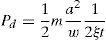
Energy generation from an electrostatic mechanism is based on the charging of capacitor plates. The distance of the charged capacitor plates, which is varied by environmental vibration or motion, changes the capacitance of the capacitor architecture. The change in the capacitance changes the voltage of the capacitor according to the basic capacitor equation (Eq. (2)):
where the charge of the capacitor Q is equal to the voltage V times the capacitance C. When the capacitance of the capacitor is decreased (by an increasing distance of the capacitor plates) the voltage across the capacitor increases (because there is a charge on the plates). Therefore, the kinetic energy due to the motion or vibration that increases the plate distance is converted into electrical energy (Goll, Zenner, & Dalhoff, 2011; Shukla & Bell, 2015).
The temperature of the human body is almost constant, but it has little changes in different situations, usually between 36°C and 37°C. Based on the thermoelectric effect, this heat can be converted to electricity (Jo, Kim, Kim, & Kim, 2012). A thermoelectric device produces voltage when there is a different temperature on each side. Some temperature sensors work based on this effect. When one node of this sensor is connected to the body and another node is in the atmosphere, the output of the sensor shows the temperature difference of the body and the environment. This mechanism is used for electrical energy generation. The output voltage of these sensors can be obtained by the following equation:
where αn and αp are sensor material coefficients and Δt is the temperature difference.3Harvesting the kinetic energy of the body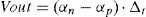
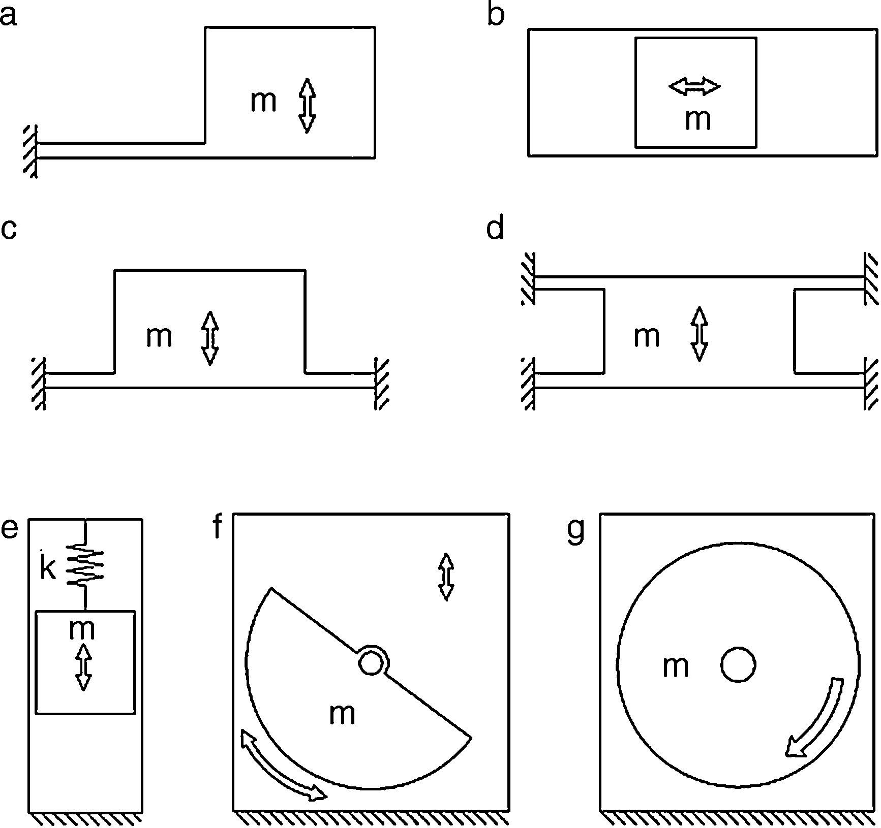
Typically, energy harvesting generators follow a cantilever-beam structure with a proof mass at the end of the beam, in spite of several other shapes that are also known, as shown in Figure 3. Usually, the conversion from mechanical energy to electrical energy consists of piezoelectric, electromagnetic, or electrostatic methods (Ylli et al., 2015).
 cantilever beam, (b) out-of-plane plate, (c) free-sliding mass, (d) in-plane plate, (e) spring–mass structure, (f) oscillating rotational, (g) continuous rotation mechanism.")
Energy harvester shapes: (a) cantilever beam, (b) out-of-plane plate, (c) free-sliding mass, (d) in-plane plate, (e) spring–mass structure, (f) oscillating rotational, (g) continuous rotation mechanism.
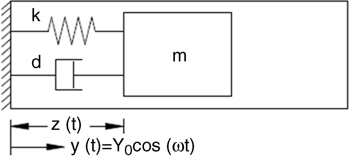
Figure 4 shows a typical structure of a mechanical energy generator. This structure (a spring–mass system) consists of a spring with constant k, a proof mass m, and a damper d (that includes energy generation damping and frictional terms).

Eq. (4) describes the spring–mass system as
where ω is the frequency in rad/s, z is the relative displacement, and Y0 is the vibration amplitude. According to the system described in Figure 4, the power dissipated into the damper is (Goudar, Ren, Brochu, Potkonjak, & Pei, 2014):
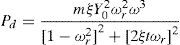
In Eq. (5), when the vibration frequency matches the natural resonant frequency (ωr=1), the maximum power is found. The last equation becomes
using a=Y0ω2, where a is the system acceleration, Eq. (6) can be rewritten as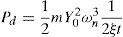
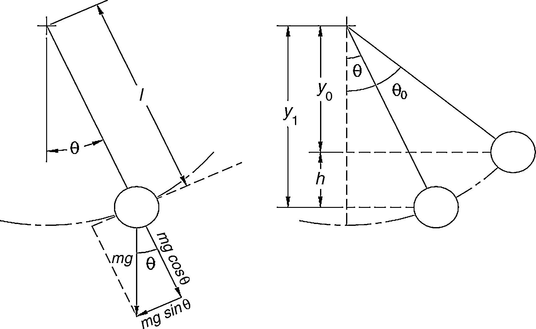
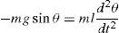
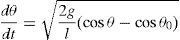
The mechanism of the proposed generator is similar to an oscillating pendulum. The relations of the pendulums can be complex; some assumptions can be made to simplify their modeling (Rao & Yap, 1995). For example, a simple pendulum is a model where a pendulum is considered to be composed of a proof mass (bob) that is connected to a mass less cord or rod, and there is not any friction while in motion (Baker & Blackbum, 2005). From Newton's second law and from Figure 5, the pendulum relation can be written asF=ma=−mgsinθ (where g is the acceleration due to gravity, m is the mass, and θ is the angular position). Assuming the relation between the arc length (S=Lθ) and the angle θ, where a=d2sdt2=ld2θdt2 and v=dsdt=ldθdt, it results in
.")
An ideal pendulum (Rao & Yap, 1995).
As the relation of motion, which can be rewritten as
For the energy conservation for this ideal system, the potential energy should be equal to the kinetic energy. Then, 12mV2=mgh or
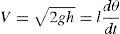
From Figure 5, h=y1=y0=1·(cosθ−cosθ0), thus, when replacing h in the last relation, leads to
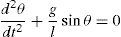
The method for solving Eq. (11) is not straightforward, but if the old techniques of the small angle approximation are used (θ≤1 or sinθ≈θ), the solution becomes
where the natural frequency of the ideal pendulum (ω0) is shown as the g/l with units of rad/s, and period T in s as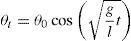

However, the proposed generator does not operate as an ideal pendulum. The real behavior has a damping component (due to energy harvesting and friction), forced oscillation, as well as large amplitude oscillations and irregular content if used for the body motion or other kinetic energy sources.
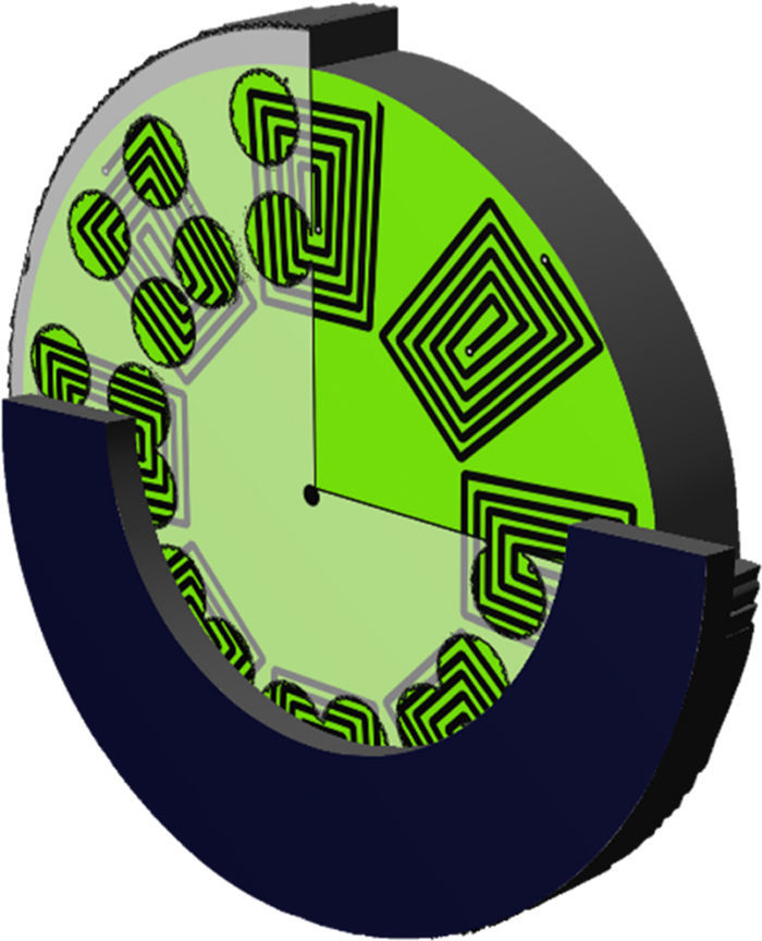
4The proposed microgeneratorIn this part, a rotary microgenerator is proposed to convert the body motions to electricity. Human activities are characterized by low frequency content (<10Hz) and large amplitudes. This type of motion source makes it difficult to design a microgenerator that matches a person's wide frequency content while doing daily activities (jogging, walking, office work, among others). The proposed generator consists of a rotor with off-center weights. Permanent magnets on the rotor are made of NdFeB with remanence Br=1.28T. Magnets are a cylinder shape and their heights and diameters are 1.8mm and 5mm, respectively. Also, the stator winding is designed to be flat. While the off-center rotor is rotated by the external forces, a voltage appears at the terminals of the coil. Figure 6 shows the model of the generator.
4.1The characteristics of the proposed microgenerator
Pendulum mechanism: pendulum and rotary mechanisms are very sensitive and different forms of external forces. Also, a rotary mechanism requires less space than a linear mechanism.
Flat structure: the flat structure of the stator and the rotor cause less total volume of the microgenerator. Therefore, it can be usable for portable electronics and medical devices or medical implant devices.
Electromagnetic mechanism: for rotary generators, an electromagnetic mechanism is very suitable. As mentioned in the previous sections, the piezoelectric mechanisms work with the deformation of the piezoelectric material. Therefore, this mechanism is not suitable for rotary generators. Also, the electrostatic mechanism produces low power.
PCB-based windings: using PCB for windings causes cheaper and less volume windings. Also, using this mechanism allows the designers to have a complicated design for windings.
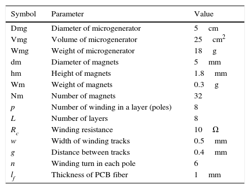
4.2The voltage produced by the coilFigure 7 shows the coil pattern used in the proposed microgenerator. In this pattern, two magnets are on each part of the coil. Table 1 shows the geometric dimensions of the micro generator and the windings.

Geometric dimensions of the proposed microgenerator.
| Symbol | Parameter | Value |
|---|---|---|
| Dmg | Diameter of microgenerator | 5cm |
| Vmg | Volume of microgenerator | 25cm2 |
| Wmg | Weight of microgenerator | 18g |
| dm | Diameter of magnets | 5mm |
| hm | Height of magnets | 1.8mm |
| Wm | Weight of magnets | 0.3g |
| Nm | Number of magnets | 32 |
| p | Number of winding in a layer (poles) | 8 |
| L | Number of layers | 8 |
| Rc | Winding resistance | 10Ω |
| w | Width of winding tracks | 0.5mm |
| g | Distance between tracks | 0.4mm |
| n | Winding turn in each pole | 6 |
| lf | Thickness of PCB fiber | 1mm |
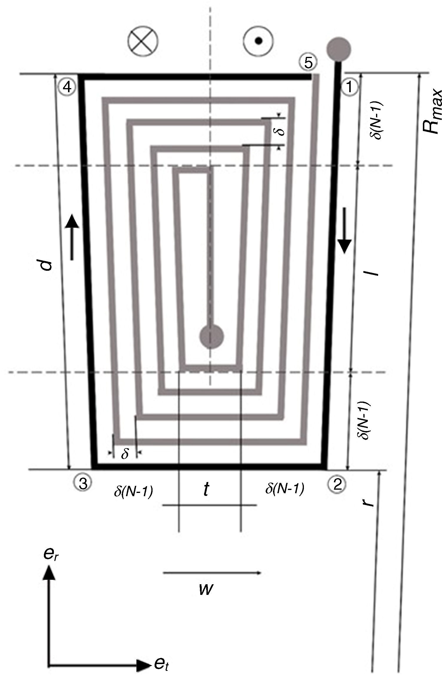
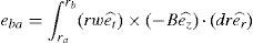
As shown in Figure 8, the model for the voltage is based on the analysis of a coil segment under a PM pole-pair. For more details, the analysis is shown for the coil segment 12345 (darker color segment, Fig. 8).

Current is flowed on the coil segment 12345 when the generator rotates (or oscillates) with an angular velocity ω (rad/s) under a distribution of the magnetic flux Bz(T). Using Fleming's right-hand rule, the current direction is imaged as shown in Figure 8.
Since radial segments 23 and 45 are parallel to the rotor velocity, there is no voltage induced on them. Therefore, voltage is induced only on the radial segments of the winding (12 and 34) when the magnets of the rotor pass over the windings. Hence, the analysis of segments 23 and 45 follows as
where the equation for a radial segment is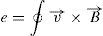
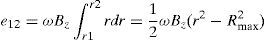
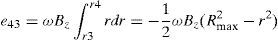
Then, the produced voltages e12 and e43 are
The produced voltage in the winding segment 12345 becomes then e15=e12+e43
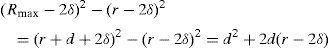
where Rmax=r+δ(n−1)+l+δ(n−1)=r+d, n is the number of winding turns, d is the length of a winding sector and δ is the width of a track plus the space between 2 tracks, thusfor the previous loop (N=2)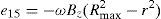

Therefore, for loop N
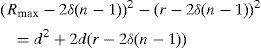
The produced voltage for the winding l sector area having N turns follows as e=e1+e2+⋯+eN:
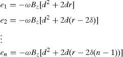
Therefore

By the triangular number definition, one can obtain:
and replacing Eq. (24) in the last term of Eq. (23) causes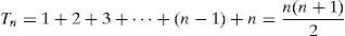


Then, the produced voltage relation for p pole-pairs of permanent magnets and L number of winding layers finally become:
4.3Analysis of the windings
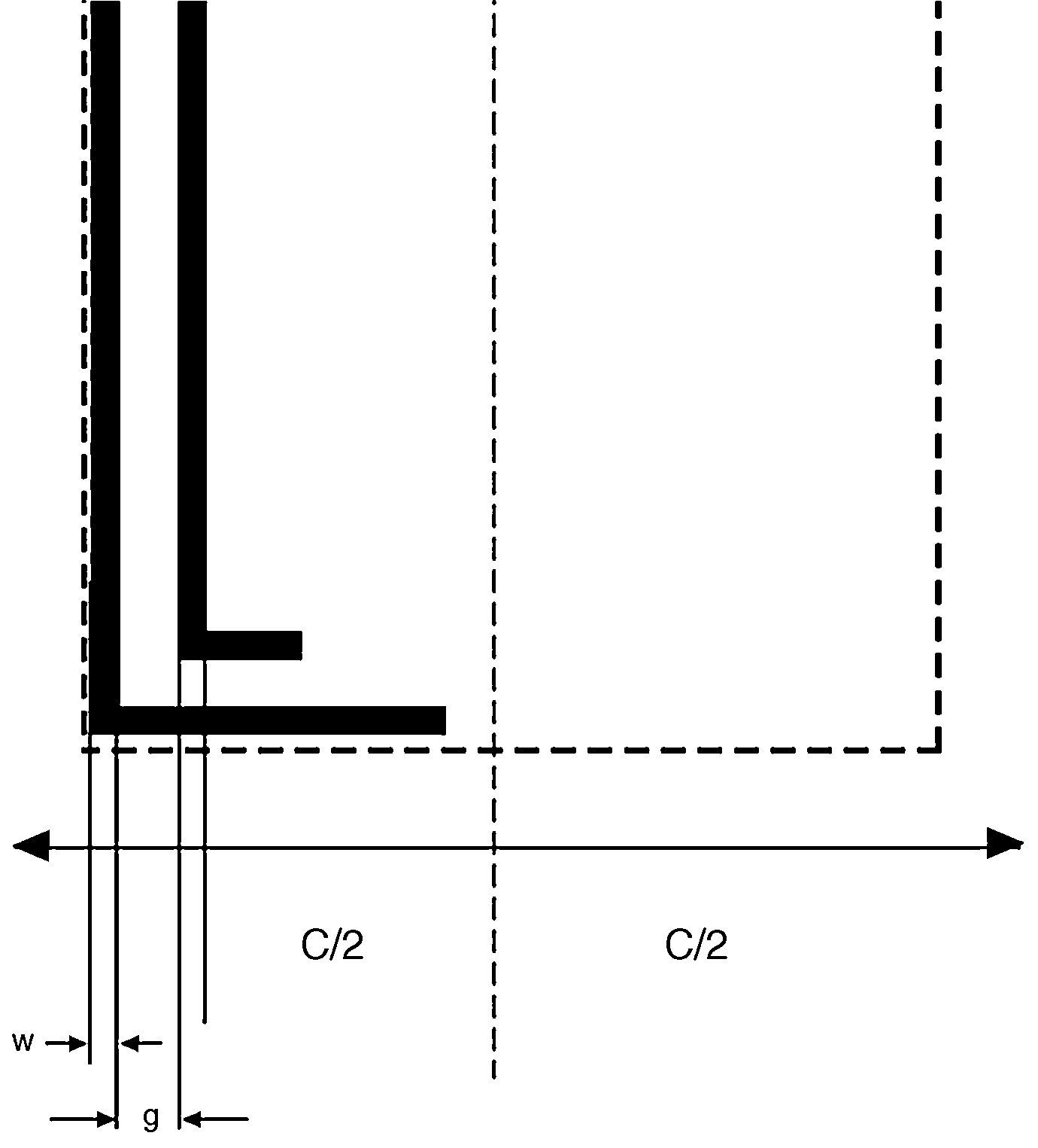
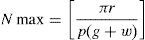
One of the first steps for the analysis of the windings is the calculation of the winding resistance. For this step, the length of the windings should be calculated. For the analysis, the winding pattern shown in Figure 8 is considered. Also, according to Figure 9, the turn numbers of the track of PCB in each sector of the winding is equal to Nmax (Eq. (29)):
where g is the distance between lines and w is the width of the copper tracks.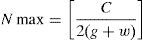

Also, C is calculated by Eq. (30).
where r is inner radius, p is the number of pairs of poles of a magnet generator. Using both Eqs. (29) and (30), it can be obtained:
To calculate the length of the windings, all of the vertical and horizontal tracks should be considered. Firstly, the length of a pair of poles is calculated. Then, this value is multiplied by the number of pole pairs and also by the number of layers of the windings. According to Figure 8, the length of the vertical tracks is:
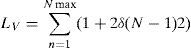
Also, the length of the horizontal tracks is:
where t is equal to 3w+2g.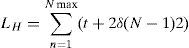
By summing Eqs. (32) and (33), the total length of a pole pair of the windings is obtained:
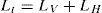
In addition, the total length of the windings of the proposed microgenerator is equal to Lt=p·l·(LV+LH), where p is the number of pole pairs and l is the number of layers of PCB. Therefore, the total resistance of the windings is equal to:
where A is the cross-sectional area of the tracks, ρ is the specific resistance of the tracks and Rc is the total resistance of the windings.4.4Power calculation
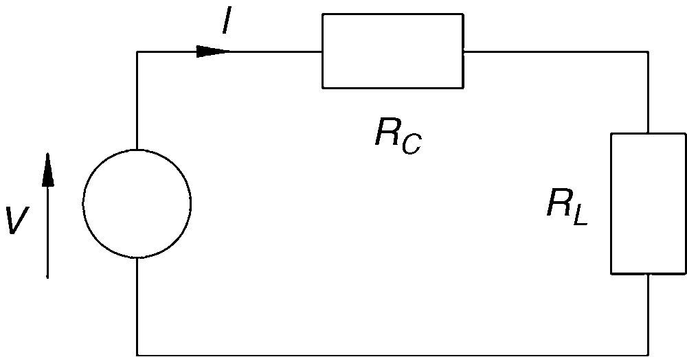
The produced power can be calculated according to the diagram presented in Figure 10 as a simplification of the proposed microgenerator circuit, the resulting current I can be calculated by Ohm's law as
where Rc is the winding electrical resistance and Rl is the load resistance. Also, the power dissipated into the load Rl is equal to
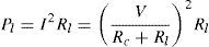

The previous relations can be helpful to determine the produced power of the proposed microgenerator. Using the theorem of the maximum power transfer (which explains that in order to have maximum power, the resistance of the load must match the internal resistance of the microgenerator, this is Rl=Rc) then the produced power is equal to
4.5Theoretical results
Based on Eq. (24) and using the parameters of the proposed system in Table 1, the output voltage of the system can be obtained for different situations. In a test, the rotor is deviated 180° to the right. Using the velocity of the rotor in this situation and considering Eq. (24), the total voltage across the windings, et, is equal to 187.06mV. Regarding Eq. (35), the resistance of the windings is 9.85Ω. Using Eq. (38), the maximum power that can be harvested from the proposed generator is 440μW.
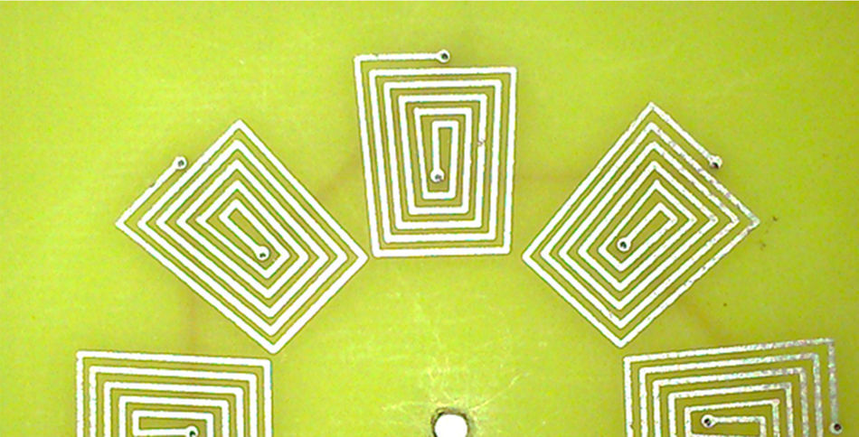
5Implementation of the proposed microgeneratorIn this section, the implementation process of the proposed microgenerator is presented. The microgenerator consists of different parts like rotor, stator and frame. The rotor consists of some NdFeB permanent magnets. Each set of four magnets makes a pair of poles and they can cover a winding on the stator. They are placed on a material and create a rotor. Different parts of the windings are series together and two end nodes are used as the output of the microgenerator. Figure 11 shows the winding of the stator on the board.

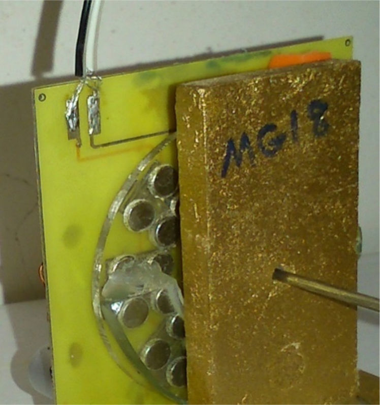
By connecting the designed rotor, the designed stator, some parts as a frame, some parts for rotation and an off-center weight, the microgenerator is completed. Figure 12 shows the photo of the designed microgenerator.
5.1Test results of the proposed microgenerator
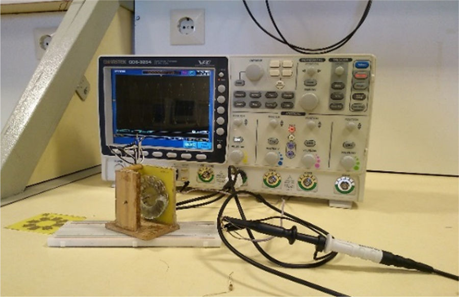
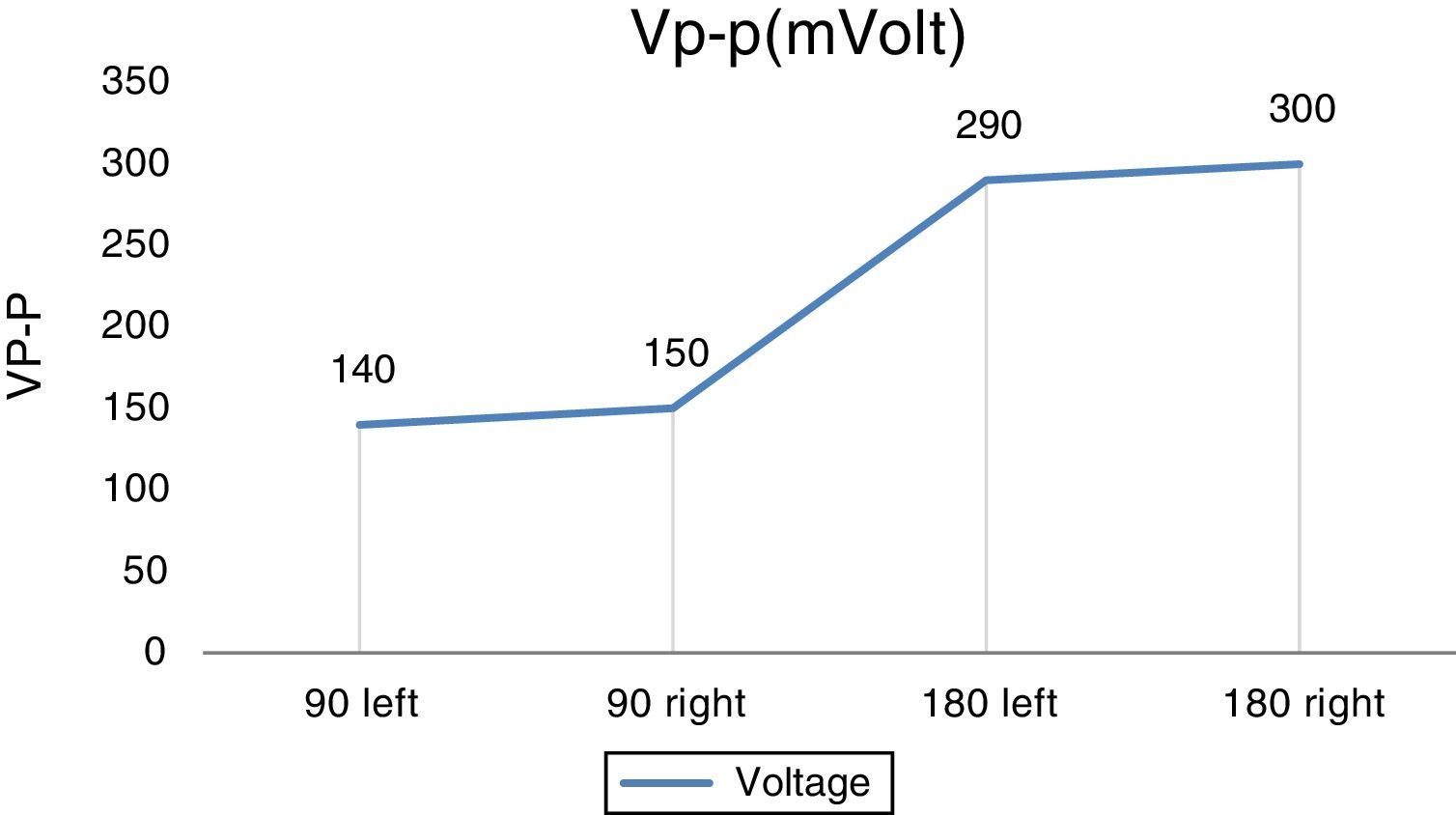
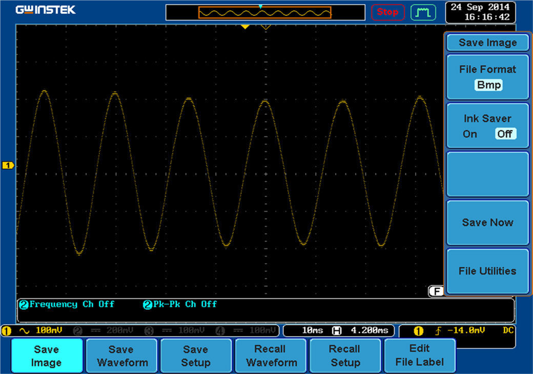
In this part, some test results are presented. Figure 13 shows the designed generator in the laboratory. The first test is a simple no-load test. In this test, the rotor is deviated in four states: 90° to the left, 90° to the right, 180° to the left and 180° to the right. Then the rotor is released. Figure 14 shows the maximum peak-to-peak output voltage of the generator in different states. Also, Figure 15 shows the output voltage of the generator with a 180° deviation to the right, in a digital oscilloscope.


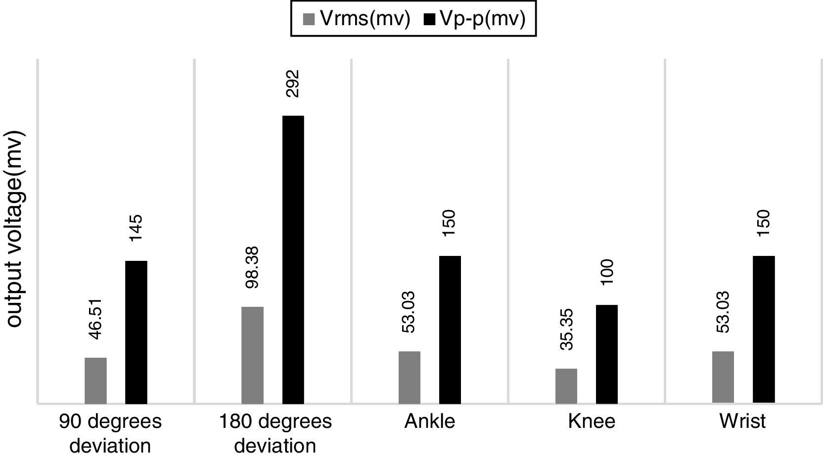
After the no-load test, the designed generator is tested with a different load and in different positions of the installation. The winding resistance of the proposed generator is 10Ω. Figure 16 shows the results for the 10Ω load in different positions of the installation: in the wrist, in the knee, in the ankle, with a 180° deviation and with a 90° deviation. It can be observed that the output voltage with a 180° deviation in rotor is the maximum.

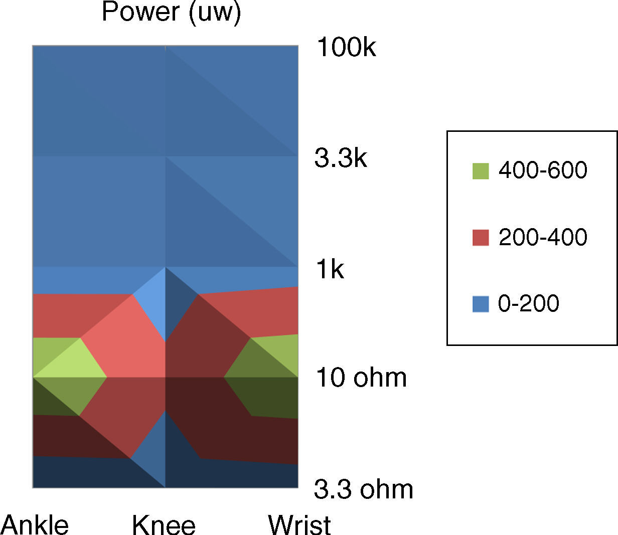
Figure 17 shows the results for different loads and in different positions of the installation. The load resistors are 3.3Ω, 10Ω, 1kΩ, 3.3kΩ and 100kΩ. Also the positions are ankle, knee and wrist. It can be observed that the output power with the 10Ω load and in the wrist is the maximum.
6Conclusion
An electromagnetic microgenerator was designed and built. This microgenerator converts human motions to electrical energy. The small size and use of a pendulum mechanism without gear are the two main characteristics of the designed microgenerator. The generator can detect small vibrations and produce electrical energy. The structure of the microgenerator has been explained in this paper. The performance of the microgenerator was evaluated by installing the generator in different parts of the body. Also, the generator was tested with different loads. The maximum harvested electrical energy during normal walking was around 416.6μW, when the generator was installed close to the ankle. This result is in agreement with the theoretical analysis of the proposed generator. This power is sufficient for different applications.
Conflict of interestThe authors have no conflicts of interest to declare.
Peer Review under the responsibility of Universidad Nacional Autónoma de México.