


This paper presents an image deformation algorithm and constructs an automatic facial expression generation system to generate new facial expressions in neutral state. After the users input the face image in a neutral state into the system, the system separates the possible facial areas and the image background by skin color segmentation. It then uses the morphological operation to remove noise and to capture the organs of facial expression, such as the eyes, mouth, eyebrow, and nose. The feature control points are labeled according to the feature points (FPs) defined by MPEG-4. After the designation of the deformation expression, the system also increases the image correction points based on the obtained FP coordinates. The FPs are utilized as image deformation units by triangular segmentation. The triangle is split into two vectors. The triangle points are regarded as linear combinations of two vectors, and the coefficients of the linear combinations correspond to the triangular vectors of the original image. Next, the corresponding coordinates are obtained to complete the image correction by image interpolation technology to generate the new expression. As for the proposed deformation algorithm, 10 additional correction points are generated in the positions corresponding to the FPs obtained according to MPEG-4. Obtaining the correction points within a very short operation time is easy. Using a particular triangulation for deformation can extend the material area without narrowing the unwanted material area, thus saving the filling material operation in some areas.
In recent years, studies on body movement behavior have been conducted in the areas of gaming, animation, and video. The most effective method to produce accurate and realistic facial expressions is motion capture, which requires specific hardware, software, and even expensive equipment. Thus, the penetration and popular use of this method is not easy. The Mehrabian oral communication effects model shows that when people speak, content accounts for only 7%, intonation and expression account for 38%, and body language with facial expressions account for 55%. Facial expressions have a major impact on interpersonal communication [1]. Recent advancements in technology have led to the wide use of networks and portable devices. Human communications often rely on instant messaging systems. In interpersonal communication, most people use expression words, default texts, and images to express themselves, thus lacking in other practices. Human emotional response is very complex and is most directly displayed by facial expressions. If people can learn the expressions and emotions in communication, then interaction and communication can be substantially increased. Generating different personal expressions in a simple, fast, and low-cost way is a widely studied issue.
This paper proposes a system for facial expression generation based on images of people with neutral expressions to generate face images with expressions. The facial expression generation system is divided into skin color segmentation, face detection, feature capture, image deformation, and correction. First, the system conducts face detection of the input image and segments the skin color areas in different color spaces. The color analysis method is used to find facial areas. After capturing the facial area in the image, the system searches and locates features (i.e., eyebrows, eyes, nose, and mouth) and defines them as feature points (FPs). When generating the expressions, the system moves the feature areas for distortion and deformation and carries out image correction of the surrounding materials to finally produce a new expression.
Research related to facial expression is mainly divided into face recognition and facial expression generation. The human face is first located in the image to make some changes, so most relevant research on facial expression is involved with face detection or recognition. Three main directions are followed in human face recognition:
- 1.
Template: Based on existing human face images, statistical analysis is used to established the template of the relative positions of a face and compare the other face images accordingly [2] [3] [4] [5]. As facial features have fixed relative positions, the templates established in advance can be used to effectively detect different face images.
- 2.
Feature: To search for the parts of facial features in the image, color difference image analysis is conducted by using facial features as standards. If the accuracy of the information is below a certain level, correctly distinguishing face structures becomes difficult. Hence, the capability of effectively positioning feature areas in human images determines the effectiveness of face recognition.
- 3.
Appearance: A large number of human face images using the Principal Component Analysis are trained to establish eigenfaces of different expressions and to obtain the total indicators by weighted average as a basis for face recognition [6] [7] [8]. In recent years, artificial neural network (ANN) and genetic algorithms (GAs) [9] [10] [11] has been used to obtain eigenfaces. Images with similar eigenfaces are inputted into the ANN system as their reference samples to train the ability of recognizing different faces.
Facial expression generation can also be divided into two directions: (1) database training by face images of different expressions to establish the facial change system [12] and (2) changing the single facial image according to the feature positions by using image deformation technology [13] [14] [15].
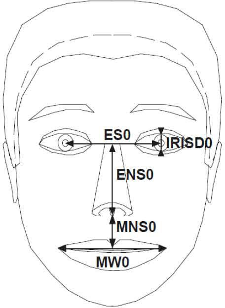
MPEG-4 is short for Moving Picture Experts Group, a set of standards for compressing video coding jointly published by ISO and IEC. In ISO/IEC 14496 standards, MPEG-4 defines the FP positions of five organs of a neutral face. This format also defines how to establish the human face image, namely, the FPs when facial expressions change and the Feature Animation Parameters (FAPs) of the movements of various FPs in video. The definitions relating to a neutral face are as follows. Eye viewing direction is in the direction of the Z-axis. Facial muscles are at a relaxed state. The edge of the iris is tangent to the eyelids. The diameter of the pupil is one-third of the diameter of the iris. The upper and lower lips are closed and the lip line is horizontal; the two corners of the mouth are at the same height. The mouth is completely closed, and the upper teeth should be in contact with the lower teeth. The tongue is flat at a horizontal state; the tongue tip should touch the junction of the upper and lower teeth.
Figure 1 shows the neutral expression face with the following elements: IRISD0 is the diameter of the iris, which is tangent to the upper and lower eyelids; ES0 is the length of the two pupil centers; ENS0 is the vertical length of the line connecting the eye centers and the center of the nose; MW0 is the connection length of the two mouth corners; and MNS0 is the length from the mouth to the nose center. These parameters are Facial Animation Parameter Units. Facial expression changes if these values (length) are changed.
![A neutral face state and FAPs [15] as defined by MPEG-4.](https://static.elsevier.es/multimedia/16656423/0000001200000006/v2_201505081706/S1665642314716712/v2_201505081706/en/main.assets/gr1.jpeg?xkr=ue/ImdikoIMrsJoerZ+w997EogCnBdOOD93cPFbanNcX6PcOHo8VDqRKrp6xHZ/NlPxKUvo805ICrHlplwxcm7hYIESfjCCTNDlVokL+8rOQ+uE0zfNvcTcQd5P+nNAsR7tyG0Argirw0CsIYDw2GxO93rpWxFoh1t4aibuFu9KCqIYYMWGEhzUZdNcg2nZuq5ZZce12bx+9W6+ZZwJToVmOtkk18D2SSqd2uVUzP9QpP45vNWDtZ9pKsIl5+Pf+xN3lJ7L6Q1u8u5uBpvpsqpsr3kqJgaFX1pA2R1VX6WvdMuhbKZrXbIYs6vvu1p/n8DQ0tVBAMjw0ZjqWmtj5kQ== "A neutral face state and FAPs [15] as defined by MPEG-4.")
A neutral face state and FAPs [15] as defined by MPEG-4.
MPEG-4 only defines FPs and their corresponding positions, but does not provide the method to capture face and FPs in the image. These FPs are positioned in the face images to make face image deformations and implement the motivation mentioned above [16]. This paper is divided into four sections. Section 1 is Introduction, explains the research theme, motive, and purpose, as well as introduces relevant theoretical literature of the research issues. Section 2 is Research methods, presents the research process and steps. Section 3 do show some Experimental results, illustrates the results of the implemented system. Section 4 gives for Conclusions, presents the results of the study.
2Research methodsThis paper uses face images of neutral expressions and forms an automatic system. After inputting the image into the system, the system automatically captures facial FPs. It then changes the FP locations using image processing techniques for the space conversion of features to generate a new expression. System processing can be divided into four blocks: skin color segmentation, noise filtering, feature positioning, and image deformation.
2.1Skin color segmentationThis section uses the color face image. Color image has the additional chrominance channel compared with the grayscale image. The use of skin color to capture human faces is a method often used in face-tracking research. This method can easily recognize and capture human face features and facilitate the image processing of the system [17]. For the positioning of the human face area, color image is used for skin color segmentation. The backgrounds of skin color and non-skin color are segmented to reduce system processing time. Considering that the relative positions of human face organs can enhance the accuracy of feature positioning, the Normalized Color Coordinates (NCC) color space of YCbCr and nRGB [19][20][24] are used for skin color segmentation. Given that the RGB color model is relatively sensitive to changes in light, it may easily result in recognition errors in skin color segmentation because of the impact of illumination strength. NCC color space can reduce the impact of the light source strength on the image. The RGB color model is thus converted into NCC for skin color segmentation. The conversion formula is as follow Eq. 1.
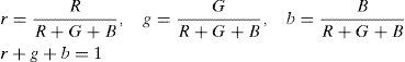
where r, g, and b are the normalized RGB colors. Only the r and g values are used in this study. The skin color distribution is in a fixed range [25]. Non-skin color pixels are filtered by setting the upper and lower bounds of the r values corresponding to the g values of the pixels. The conditional equation is as follow Eq. 2.
Meanwhile, the r and g values of the white pixels after normalization are at 0.33 in the range of Eq. 2 and are regarded as skin color that results in noise. Hence, when the r and g values are within the circle with 0.33 as the center and 0.02 as the radius, the pixels are regarded as white and should be filtered. The conditional equation is as follow Eq. 3.

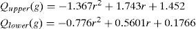
Some colors similar to skin color, such as yellow-green and orange, are easily left behind. Thus, more accurate skin color definitions should be used for separation. The RGB strength statistics of skin pixels are shown in literature [27]. The skin color segmentation can add Eq. 2 by inputting the normalized pixel (r and g) function S while combining with the white pixel filtering condition of Eq. 3 to derive the conditional equation of Eq. 4.
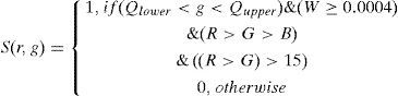
If a face image has brown hair after the skin color segmentation, the hair pixels can still leave residuals to form noise. As CbCr space has considerable detection capability in the case of similar colors [18] [20] [21], YCbCr is used to strengthen the filtering of similar skin colors. The conversion equation from RGB to YCbCr color space is as follow Eq. 5.
According to the Y (brightness) conversion formula, B (blue) has a minimal impact on the brightness intensity. When using NCC color space for skin color segmentation, the b value is not used; only r and g values are used for this reason. The yellow-brown hair pixels are filtered by the following conditional equation of Eq. 6 for YCbCr images.
Thus, skin color segmentation has separated the skin color area and the background. Through binarization, the filtered pixel is set as 0 (black), the retained pixel is set as 255 (white), and the image can be optioned for possible regions of the face.
2.2Noise filteringAfter skin color segmentation, many scattered and broken pixels are judged as skin color. The noise can easily increase the difficulty in feature capture. As the face occupies a block of continuous skin color, morphological operations [22] [23] are used to reduce such noise to remove broken and redundant blocks and to connect the thin, long cracks and gaps. The basic operations of morphology include dilation and erosion. The operation is based on structuring elements that are the factors of interest of the image. When the scanned pixel is consistent (inconsistent) with the structuring element, the pixel is added (deleted). No limitation on the size and shape of the structuring element exists, and the result inside the original image object or the surrounding subject does not necessarily equate to the morphology of the structuring element. This study used 3 × 3 squares as the operational unit, with its center serving as the center of the structuring element. Besides dilation and erosion, operations such as opening, closing, cleaning, and filling are carried out during the noise filtering process. All the operations are based on the binarized black and white images.
The face is usually the large continuous block of skin color pixels. Connected-Component Labeling [27] should be used to accurately identify the face area by filtering the small blocks outside the face as noise. Connected-Component Labeling is an image processing operation that identifies the continuous pixels blocks in the image. This operation is usually employed in the processing of binarized images. The connection methods include four-adjacent and eight-adjacent pixels, which are judged as parts of the same block. Labeling defines adjacent points with the same label values to distinguish the link block of the pixel. This study used the eight-adjacent method to process the pixels one by one with the center of the 3×3 mask. The two major steps of the processing process [26] [28] are Label-Assigning and Label-Merging.
2.3Feature positioningAs the chin and the neck are of skin color in skin color segmentation, they can be easily regarded as continuous skin color blocks. Thus, the neck may be misjudged as the face area, which increases the difficulty in face detection, positioning, and feature capture. Hence, the chin and the neck are segmented first.
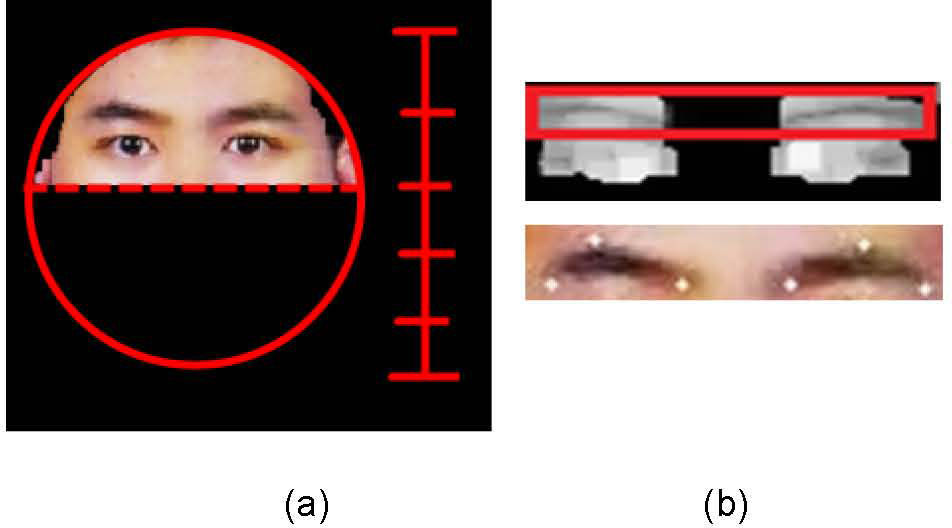
The average human face aspect ratio is about 1.3 to 1. The segmentation of the left and right parts of the face and the background can thus be processed. The face area can be obtained using the face width based on the maximum length from the left to the right side of the face. The multiplication of the face width is used as the length of the face. By depicting an oval with a face width as the short axis and the face length as the long axis, the area of the face covering the five organs can be obtained. After defining the facial area, the positioning of the eyes, eyebrow, mouth, and nose can be completed.
Eye positioning:The eye area consists of the white with high brightness and the pupil with low brightness. It is characterized by the sharp contrast of the pupil and the white. The eye has a different grayscale and color as the surrounding skin colors. Hence, the RGB image is converted into YCbCr color space. EyeMap [18] [29] is used to highlight the eye region. The Y values stand for the brightness features. The EyeMap operation is applied, and the operational equation is as follow Eq. 7.
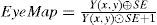
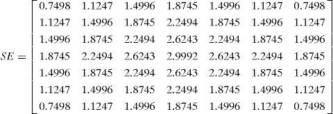
where is the dilation operation of image brightness channel Y using mask SE, and is the erosion operation. After the EyeMap operation, the result, including the eye area, can be obtained. However, using EyeMap only cannot accurately position the FPs of the eye. Canny edge detection is used as the auxiliary condition for the positioning of the FPs of the eye edges to more accurately capture the eye corner and eyelids.
Edge detection identifies the areas of dramatic changes in grayscale in image processing. Boundary points that are usually in the object’s border area are also commonly used for cutting objects and background. Considering that most of the face area is of skin color, the eye has black and white color and the contrast to the skin color is great. Edge detection can highlight the possible eye boundaries.
The eye is generally in the upper half of the face, so it can be identified in approximately the upper two-fifth section of the capture face region. After the aforementioned image processing, the following elements can be calculated. In skin color segmentation, the eye area is removed because of the large gap with the skin color so that the eye area is black in the binarized image. After the EyeMap operation, the results with the eye area can be obtained. Canny edge detection can display the pixels of possible boundaries. According to the above three types of results, the eye area is labeled in the EyeMap. The non-skin color in the skin color segmentation result and the pixels of values in the Canny edge detection result are determined to label the FPs of the two eyes.
Eyebrow positioning:According to the geometric relationships of human facial features, the eyebrow is above the eye at a fixed relative position. Eyebrow positioning is thus performed after capturing the eye features. Eye positioning using EyeMap can highlight the area of great black and white contrast to highlight the eyes, eyebrows, and nose. This study then searches for the eyebrows in the area above the eyes after locating the eyes.
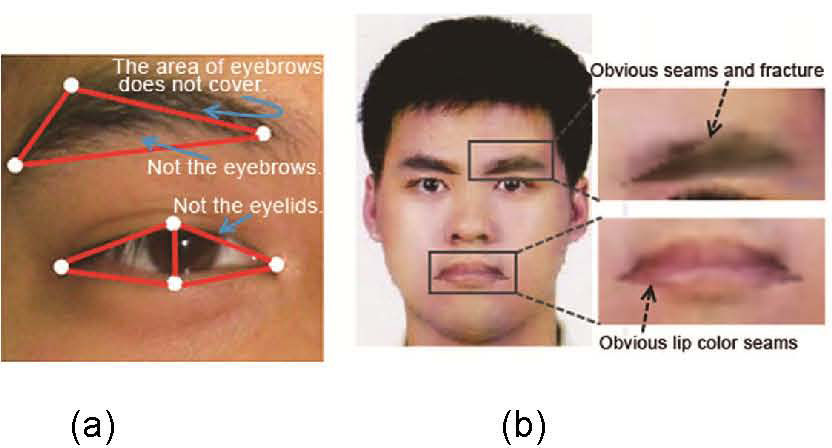
According to the relative position of the eyes and the eyebrows in the possible area of the eyes (Figure 2a), the eyebrow FPs can be obtained based on the following rules. Points close to the left and right ears with the lowest Y coordinates are FPs of the ends of the left and right eyebrows respectively. The highest point of the Y coordinate is the FP of the upper tip of the eyebrow. If more than one point exists, the points of the Y value closest to the left and right ears are the FPs of the upper tips of the left and right eyebrows respectively. Points with the X coordinate closest to the face center and the lowest Y coordinate are the FPs of the left and right eyebrows. The captured eyebrow FPs are labeled in the image as shown in Figure 2(b).
Mouth positioning: area at the upper two-fifths of the face is the eyebrow area, (b) eyebrow capture FP labeling results.")
Lip color pixel detection [18] [29] is used to capture the mouth FPs. According to the lip and skin color pixels’ r-g distribution, the lip color pixels are scattered at the lower edge of the skin color pixel range. The skin color segmentation judgment equation is used for modification as follows Eq. 8.
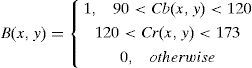
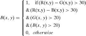
According to the statistical results of the lip color RGB histogram distribution [27] coupled with Eq. 9, the segmentation B(x, y) of the lip color can be strengthened.
As lip color and similar colors do not account for a large percentage of the face after the lip color segmentation, these parts should be in the lower half of the face. Connected-Component Labeling is used to find the maximum continuous area as the possible range of the mouth. For a more accurate positioning of mouth, this study used the method proposed by Hsu [18] and MouthMap [29] to highlight the mouth area. MouthMap uses the YCbCr color space with the following operational equation Eq. 10.

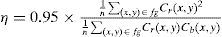
where Cb and Cr are obtained from the YCbCr color space for normalization in the range of [0, 255], n is the number of pixels of the area against the face, and fg is the range of the input image.
By the binarization of the MouthMap results and the segmentation of the lip colors to determine the lip color areas, the FPs for mouth positioning can be obtained based on the pixels of value. The steps are as follows. The center of the line between the leftmost and rightmost pixels is used as the X coordinate value of the mouth center. The uppermost and lowermost pixels with the X coordinate are used as the upper and lower FPs of the mouth, and the center of the line between them is used as the center of the mouth. Among the leftmost and rightmost pixels, the points at the shortest distance from the center on the Y coordinate are used as the left and right FPs of the mouth. The center of the line between the mouth center and the left and right mouth corners is the X coordinate. The points with the highest and lowest Y coordinates by vertical scanning are set as the FPs of the central area of the mouth.
Nose positioning:The nose is located between the eyes and the mouth. Its positioning should thus be performed after capturing the features of the eyes and the mouth. The nose can be found in the area from the center of the line connecting the two eyes and the upper part of the mouth. The positioning of the nose is determined by three steps: the positioning of the nose center, the wing of the nose points at both sides, and the nose bridge points at both sides.
In the first step, the RGB image is converted to grayscale. In the EyeMap operation of eye detection, the nose is highlighted for its darker color. The nostrils are more prominent on the face and are at a lower position when viewed from the front. Thus, the lowest points of the nostrils are used as the Y coordinate of the central point of the nose, and the central point of the nostrils is used as the X coordinate. In the second step, the aforementioned Canny edge detection results can highlight the nose edge. The positions scanned first are the points outside of the nose. If more than one leftmost and rightmost point exists, the points at the lowest position are the FPs of the nose wings at both sides. In the third step, the Sobel operation results are used. The central points of the line connecting the nose’s center of gravity to the eye centers are the Y and X coordinates. The leftmost and rightmost points in the vertical Sobel operation are the nose bridge FPs.
2.4Image deformationImage deformation is based on pixel coordinate conversion. In computer graphics research, Delaunay (1934) proposed to use triangles as the smallest unit for conversion and cut the point set in the image into triangular meshes through Delaunay Triangulation (DT). This technique is widely used in the construction of three-dimensional (3D) models [30]. Triangulation segments the point set into a triangle set. Changes in facial expressions are concentrated in the eyebrows, eyes, and mouth. If the entire face is segmented in expression deformation, this condition increases the triangular operations, and the wrinkles cannot be processed by triangulation operations. The organs are thus divided into different areas. Their FPs for expression have been identified in the previous step. The FPs are processed by triangulation.
A triangle is used as the unit for the individual coordinate conversion operation of image deformation. The area method is employed to determine whether the pixel coordinates are located inside the triangle. As to the coordinates of the three points [(Ax, Ay), (Bx, By), and (Cx, Cy)] of triangle ABC, the operational equation is as follow Eq. 11.

If a point P exists to allow the areas of triangles PAB, PAC, and PBC to equal the area of triangle ABC, then P is inside triangle ABC.
Face deformation research often uses the triangular mesh method, which is derived from the 3D modeling polygon using the face triangle formed by the least number of points as the unit [31]. The combination of a large number of triangular surfaces is used to describe the various polygons or polyhedrons extremely close to the reality curved surfaces. Graphics with more details and more complex shapes require more triangles. Using the entire face for triangulation [32] increases triangulation computation when triangular mesh characteristics are utilized as the basis for deformation. The areas of facial organs require more triangles for deformation. Therefore, the irregular polygons of the facial organs are composed of a number of triangles segmented by FPs. The DT operation can then be omitted. Instead, the facial organs are segmented by the triangles for deformation as previously defined by the system. Face image deformation may result in the discontinuity of surrounding area images and the organ image. As such, the surrounding area should be processed by triangulation alone, and the deformation operation should be performed to achieve the purpose of correction.
The face area triangulation and FP coordinate conversion result in many noise pixels and deformation area borderlines that obtain unnatural expressions. The interpolation method should be applied to compensate for the errors and damage caused by such deformations. Before the interpolation, the coordinates after the deformation should be converted. The coordinates in the original image should also obtain the surrounding pixel values required for the interpolation. The steps are as follows:
- 1.
Take a point A in the triangle ΔABC as the starting point and the sides of A with another two points B,C as two vectors AB⇀(X1,Y1) and AC⇀(X2,Y2).
- 2.
Points inside the triangle are considered as linear combinations of the two vectors. In case any point P is inside the triangle, the vector from the start point A to P is AP⇀(m,n). The joint solution to the equations of X1 t+Y1 s = m and X2t+Y2s = n. (t, s) is the coefficient of the vector linear combinations.
- 3.
After obtaining the (t, s) from the coordinates of the deformed image, they are converted into the vectors A′B′⇀ and A′C′⇀ of the original image ∆A′B′C′. The multiplication of the two vectors with the vector linear combination coefficient (t, s) an generate coordinates (X′, Y′).
The triangulation method of this study is based on the MPEG-4-defined facial FPs because the location and changing areas of features are in a fixed range. These features have been defined in FP capturing to highlight the relative positions of the organs. The coordinates of the deformed image and the FPs are defined according to the coordinates of the same image. Thus, the corresponding points of each pixel in the original image, as well as the pixel information for correction, can be obtained.
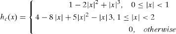
The original purpose of this method is to accurately determine the corresponding positions of the pixels in the deformed image and the original image for image correction. However, the corresponding positions to the original image is not limited by the same coordinate system because the triangle is regarded as a start point, and two vectors and all the points inside the triangle are the linear combinations of the two vectors. This study only needs to capture three points in the original image as the start point and two vectors to generate any specified area of the original image in a random location of the deformed image. After coordinate conversion, some pixel values may fall on the non-integer coordinates. However, the pixel values of the digital image should fall on integer coordinates, such that those falling on non-integer coordinates become noise. To display the pixels correctly, bicubic interpolation processing of the corresponding coordinates in the original image is applied to the pixel points after deformation. According to the pixel values of known surrounding integer coordinates, the convolution of the 16 surrounding points is performed based on Eq. 12.
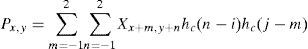
where hc is the kernel function of the convolution, and the equation is as shown in Eq. 13.
The segmented triangles are processed according to the FP sets by following the aforementioned steps until all the triangles in the face area are processed and corrected. Finally, the information of the deformed image is filled back into the original image to generate a new expression image.
3Experimental results3.1Feature positioningThe face image is first loaded into the system. The system performs skin color segmentation to filter white points, as well as areas with colors similar to skin color and brown hair, to determine the area of skin color. The result undergoes binarization processing to facilitate noise filtering. After determining the skin color area, the morphological opening operation is used for noise filtering to reduce fragmented and scattered points because hair and sideburns can easily result in cracking in the opening operation of the ear and face areas. Therefore, a closing operation is executed after the opening computation to connect the ears with the face and to fill up small blanks. Connected-component labeling is used to find the maximum continuous skin color area, and area removal operation is conducted to remove some noise blocks and outstanding boundary pixels. Area filling operation is performed to fill the inside of the skin color area. The face and neck are in skin color, such that the neck may be easily taken as the face during skin color segmentation. To control the influence of the neck on human face, the Canny edge detection method [7] is applied to identify the chin borders. The chin contour is affected by the light source and the presence of a beard. The results of Canny edge detection can be discontinuous and may not be a major part of the chin contour. The results cannot be used as the basis for neck and chin segmentation. Therefore, the face aspect ratio is used as the segmentation standard. Face aspect ratio is delineated by the top edge of the face and the face width. The face aspect ratio is approximately 1.3 to 1. As experimental testing results suggest, the face width is at its widest at the line connecting both ears. As a result, the face aspect ratio after the deduction of hair is approximately 1.1 to 1; if the forehead is covered by hair, the ratio is 1.05 to 1. In this experiment, 1.1 is used as the delineation ratio. The deviation in case of a shorter axis when both ears are covered by sideburns is negligible. The possible face area can be described by an oval, with the face length as the long axis and face width as the short axis.
Eye positioning: after determining the face area, the next step is to capture the FPs of the eyes, mouth, nose, and eyebrows. First, the eye FPs are captured, and the image is converted to grayscale. The possible eye area can be identified by applying the EyeMap operation to the grayscale image. Meanwhile, the possible eye boundaries can be identified by using Canny edge detection.
Finally, in the upper blocks of the face area, EyeMap, non-skin color area determined by skin color segmentation, and Canny edge detection can be used to identify and label the eye FPs in the image. Analysis shows that the eye is subject to the influence of light source, black eye, eyelash, and sparse eyebrow. Therefore, some rules are set to limit the range of eyes. Scanning is conducted to the left and right from the start point with the X coordinate of the face area central point in the downward direction. The scanning rules are as follows: (1) The distance between the upper and lower ends of the eyes should not be more than two-thirds of the distance between the left and right ends of the eyes. If the distance is greater than two-thirds, it is likely to fall on the eyebrow. Thus, scanning should be performed with two-thirds of the distance between the left and right ends of the eye as the border, and the upper and lower ends should be reset. (2) The Y coordinates of two eye corners should not be beyond the upper and lower FPs. If the coordinates are beyond the FPs, the left and right ends should be scanned with the upper and lower FPs as the borders. (3) The distance between the left and right ends of the eye should not be more than 2.5 times the distance between the upper and lower ends; if the value is beyond, the eye corner closest to the nose is used as the fixed point, and the distance of the fixed point from another eye corner is set as 2.5 times the upper and lower end points. The center of the line connecting the left and right end points is used as the X coordinate in scanning to set the upper and lower end points.
Eyebrow positioning: human eyebrow is affected by skin color, fine hair, and hair edge during eyebrow capture, and the central area of the eyebrow is relatively black after the application of EyeMap. However, the positioning results suggest that FPs are inside the eyebrow or the hair position and dark circle. To enhance the accuracy of deformation and reduce the degree of unnaturalness, the following rules are used to expand the range covered by eyebrow FPs and to correct FPs with significant errors: (1) Eyebrow FPs must be above the FPs of the eye. (2) The distance between the left and right FPs of the eyebrow is longer or equal to the distance between the left and right FPs of the eye. (3) FPs above the eyebrow should be located between the eyebrow start point and eyebrow end point. (4) Verify whether the distance between the eyebrow upper point and the eye upper point is more than three times the eye height. If the distance is longer, the FPs may fall in the hair. The eyebrow upper point should be repositioned based on the limitation. (5) Check whether the eyebrow start point and eyebrow end point are higher than the eyebrow upper point; if so, the eyebrow start point or eyebrow end point should be re-positioned in the range between the eye upper point and eyebrow upper point.
Mouth positioning: the mouth capture process first converts the image into YcbCr and then executes Mouth Map operation for the lip color segmentation of the original RGB image. The results of the two processes are compared and combined to identify the mouth boundary points.
Nose positioning: the nose can be found in the area from the center of the line connecting the eyes to the upper edge of the mouth. EyeMap is used for the positioning of the central point of the nose, Canny edge detection is used for the positioning of the wings of the nose points at both sides, and Sobel vertical edge detection is used for the positioning of the nose bridge points at both sides.
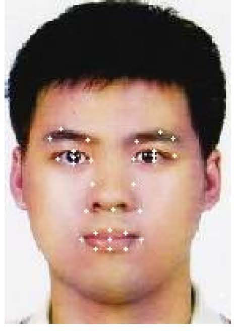
After completing all the feature capturing steps, the results are integrated and labeled in an image, as shown in Figure 3.
3.2Facial expression generation
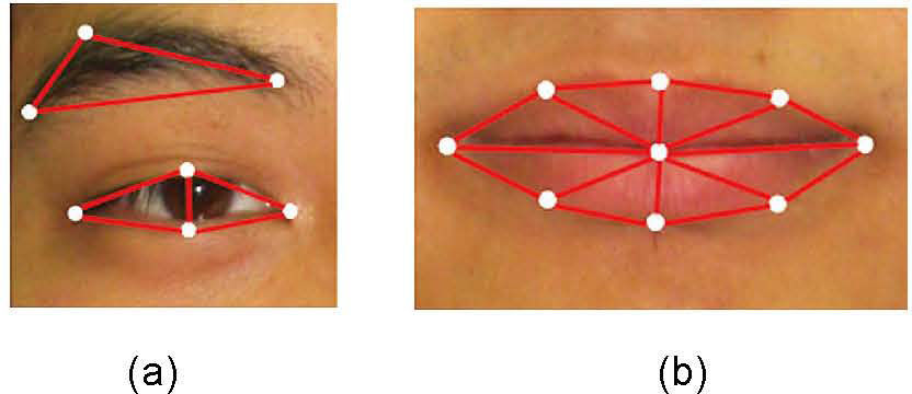
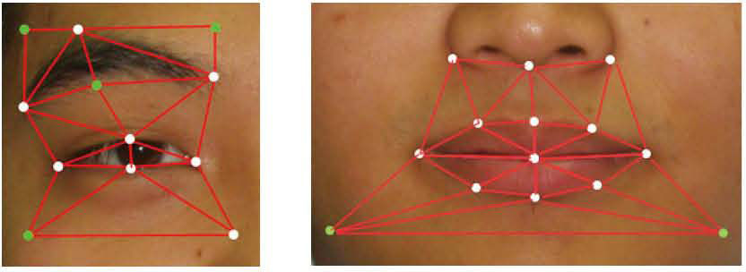
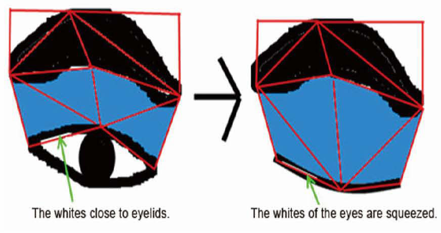
The triangulation of the FPs of the eyebrow, eye, and mouth with individual organs as units is shown in Figure 4. Changes in the mouth are often associated with lip directions, and the expressions are closely related to the direction of the mouth corner. By connecting the mouth center with other FPs, the segmented triangles can ensure the segmentation of the upper and lower lips along the lip line. However, the triangular areas segmented according to the FPs defined by MPEG-4 cannot cover the entire organ area. During deformation, the area to be deformed has clear boundaries from the surroundings and looks unnatural, as shown in Figure 5. Eye closing cannot be achieved because the eyes do not contain eyelids. The materials surrounding the organs and the deformed area should be corrected to increase additional points for wrapping the deformed organ to achieve the purpose of surrounding correction. The additional points are known as the correction points.
 eyebrow and eye triangulation, (b) mouth triangulation.")
 if the eyebrows cannot be covered after FP triangulation, then the eyelids cannot be covered by the eyes. Thus, eye closing cannot be realized, (b) the areas covered and not covered by eyebrow deformation exhibit an evident gap. The mouth and skin color areas have apparent boundaries after the deformation of the mouth. mouth.")
Triangles and deformation results according to the FPs defined by MPEG-4: (a) if the eyebrows cannot be covered after FP triangulation, then the eyelids cannot be covered by the eyes. Thus, eye closing cannot be realized, (b) the areas covered and not covered by eyebrow deformation exhibit an evident gap. The mouth and skin color areas have apparent boundaries after the deformation of the mouth. mouth.
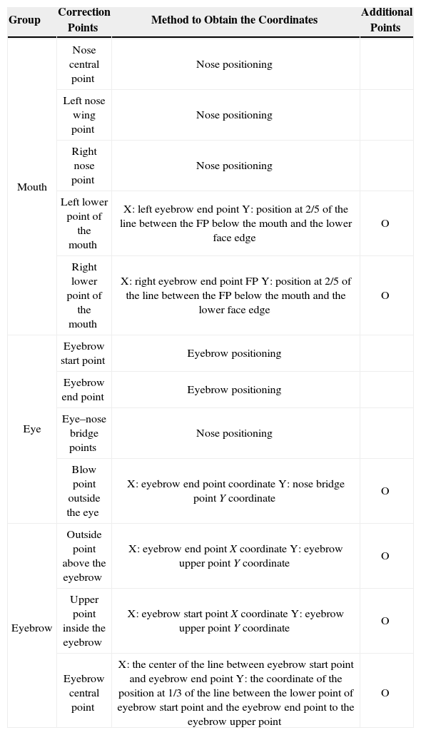
The additional correction points are used for the generated triangles surrounding the organs. Therefore, the coordinates are generated based on the coordinates of the obtained FPs. In the area above the mouth, the nose center and wing of nose point, along with the mouth FPs, can be applied in triangulation processing without additional correction points. As regards the area below the mouth, the coordinate at the two-fifth position of the line connecting the FP below the mouth and the face lower edge is the Y coordinate, and each correction point is defined at the left and right according to the X coordinate of the left and right eyebrow end points respectively.
The eyebrow is often curved. Thus, the triangle based on three FPs often includes an area of skin color, and the eyebrow edge is often eliminated. This condition results in an apparently unnatural fault in deformation. The problem of curve can be compensated by adding an eyebrow central point below the eyebrow. The X coordinate of this point is the center of the line between the eyebrow start point and the eyebrow end point, while the Y coordinate is the coordinate of the position at one-third of the line between the lower point of the eyebrow start point and the eyebrow end point to the eyebrow upper point. For the eyebrow edge, correction points are added above the eyebrow start point and the eyebrow end point to cover the entire eyebrow. The Y coordinate is the Y coordinate value of the eyebrow upper point, while the X coordinate is the X coordinate of the eyebrow start point and the eyebrow end point. The eyebrow lower edge is connected to the eye FPs to achieve the partial correction of eye and eyebrow.
Eye deformation focuses on the eyelid movements during eye closing and the upward movements of the eye induced by the pressure of the muscles below. Thus, eye deformation is the same as mouth deformation in that the upper and lower correction points should be increased. As regards the upper correction points, the range of the eyebrow is wider than that of the eye. Thus, after adding the central point of the eyebrow, three additional points can satisfy the upper correction. The inside points in the area below the eyebrow uses the nose bridge FPs. Thus, a correction point must be added in the area below the eyebrow. The X coordinate of this point is the X coordinate of the eyebrow end point, while the Y coordinate is the Y coordinate of the nose bridge points.
After the triangulation processing of the added correction points and FPs, the full task prior to deformation is completed. The results are shown in Figure 6. All the additional correction points include two for the mouth and eight for both eyes. The remaining area uses the FPs obtained during the feature capturing stage. All the added points are listed in Table 1.
.")
Correction points for mouth, eye, and eyebrows.
| Group | Correction Points | Method to Obtain the Coordinates | Additional Points |
|---|---|---|---|
| Mouth | Nose central point | Nose positioning | |
| Left nose wing point | Nose positioning | ||
| Right nose point | Nose positioning | ||
| Left lower point of the mouth | X: left eyebrow end point Y: position at 2/5 of the line between the FP below the mouth and the lower face edge | O | |
| Right lower point of the mouth | X: right eyebrow end point FP Y: position at 2/5 of the line between the FP below the mouth and the lower face edge | O | |
| Eye | Eyebrow start point | Eyebrow positioning | |
| Eyebrow end point | Eyebrow positioning | ||
| Eye–nose bridge points | Nose positioning | ||
| Blow point outside the eye | X: eyebrow end point coordinate Y: nose bridge point Y coordinate | O | |
| Eyebrow | Outside point above the eyebrow | X: eyebrow end point X coordinate Y: eyebrow upper point Y coordinate | O |
| Upper point inside the eyebrow | X: eyebrow start point X coordinate Y: eyebrow upper point Y coordinate | O | |
| Eyebrow central point | X: the center of the line between eyebrow start point and eyebrow end point Y: the coordinate of the position at 1/3 of the line between the lower point of eyebrow start point and the eyebrow end point to the eyebrow upper point | O |
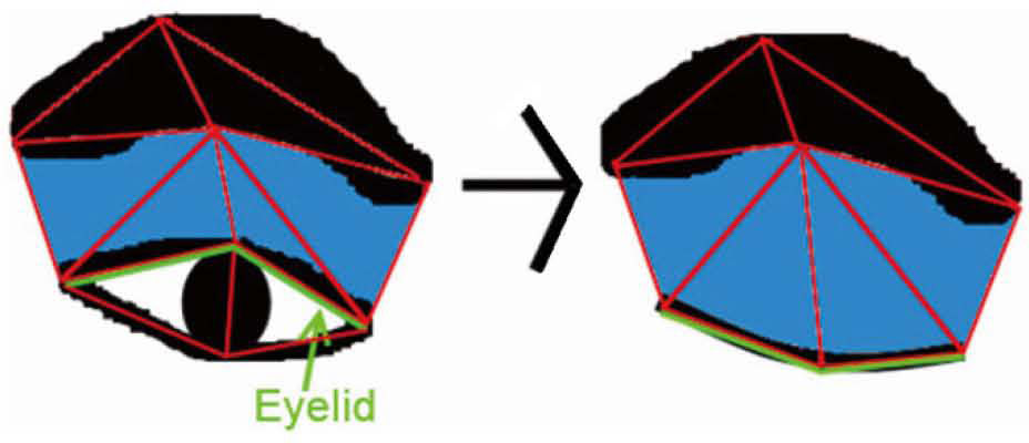
Various facial expressions are formed by the changes in facial organs. The shapes of the eye, mouth, and eyebrows are the major areas of influence. For the changes in the eyes, the eyelids are the major movable area. The eyelids can cover the internal area of the eye after deformation. Thus, the use of eye FPs alone cannot process the eyelids. The FPs of the eye and eyebrows are thus used in combination for triangulation. The movement of eyelids refers to the upward and downward movement of the central area with fixed eye corners. The eye shapes may shrink in the upward or downward direction. Thus, an additional eyebrow central point is added. The X coordinate of this point is the central value from the eyebrow start point to the eyebrow end point, while the Y coordinate is that of the point closest to the eye in the eyebrow area of the same X coordinate. The eyebrow center, eye corner, and eye upper ends are segmented into two eyelid triangles, as shown in Figure 7.

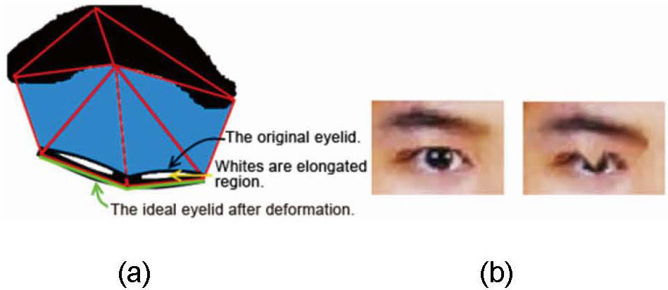
However, for the deformation results of such segmentation, the eyelid area segmented by triangulation with four FPs for the positioning of the eyes may generate eye white parts. In the eye closing deformation, the triangle with the line between the eye upper edge and the eyebrow center as the bottom side is expanded when the height remains almost unchanged. Meanwhile, the eye white area along the triangle edges is expanded in width. As a result, the eyelids cannot cover the eye area, and numerous unnatural results are observed in the eye white area, as shown in Figure 8.
 diagram illustrating a result wherein eyelids cannot actually cover the eye area and the eye white area becomes noise. (b) eyelid deformation cannot cover the entire eye and generates unnatural results.")
The eye triangulation method has limited application in normal eyelid deformation, as shown in Figure 9. The line between the eye and eyebrow is segmented by triangulation with the eyebrow start point (eyebrow end point), eye corner, and eye upper point. In eyelid deformation, such segmentation can make the triangle thinner and longer, and the eye white area becomes smaller owing to the pressure of the triangle edges. In this way, when the eyes are closed, the area becomes very small. The results are shown in Figure 10.


Eyebrow changes in expressions mainly include frowning and eyebrow raising. The deformation results from the movement of the distance between the eyebrow start point and the eyebrow end point at a certain percentage. The changes in FPs can be illustrated as shown below.
- 1.
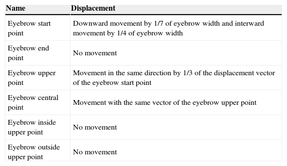
Frowning: change is shown in Table 2.
Table 2.Movement of FPs when frowning.
Name Displacement Eyebrow start point Downward movement by 1/7 of eyebrow width and interward movement by 1/4 of eyebrow width Eyebrow end point No movement Eyebrow upper point Movement in the same direction by 1/3 of the displacement vector of the eyebrow start point Eyebrow central point Movement with the same vector of the eyebrow upper point Eyebrow inside upper point No movement Eyebrow outside upper point No movement - 2.
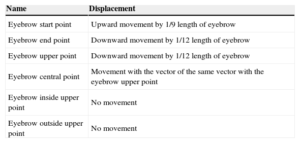
Eyebrow raising: change is shown in Table 3.
Table 3.Movement of FPs when raising eyebrows.
Name Displacement Eyebrow start point Upward movement by 1/9 length of eyebrow Eyebrow end point Downward movement by 1/12 length of eyebrow Eyebrow upper point Downward movement by 1/12 length of eyebrow Eyebrow central point Movement with the vector of the same vector with the eyebrow upper point Eyebrow inside upper point No movement Eyebrow outside upper point No movement
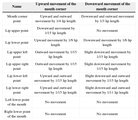
Mouth deformation mainly results from mouth corner adjustments. Similar to eyebrow deformation, mouth deformation is divided into the upward and downward movements of mouth corners. The movements of FPs are shown in Table 4. The colors at the border of the lip and surrounding skin have no apparent fault, and the lip has no apparent triangular edge. Thus, the image appears relatively natural.
Movements of the FPs during mouth deformation.
| Name | Upward movement of the mouth corner | Downward movement of the mouth corner |
|---|---|---|
| Mouth corner point | Upward and outward movement by 1/4 lip length | Downward and outward movement by 1/3 lip length |
| Lip upper point | Downward movement by 1/15 lip length | No movement |
| Lip lower point | Upward movement by 1/9 lip length | Downward movement by 1/6 lip length |
| Lip upper left point | Outward movement by 1/15 lip length | Slight downward movement by 1/15 lip length |
| Lip upper right point | Outward movement by 1/15 lip length | Slight downward movement by 1/15 lip length |
| Lip lower left point | Upward and outward movement by 1/15 lip length | Slight downward and outward movement by 1/15 lip length |
| Lip lower right point | Upward and outward movement by 1/15 lip length | Slight downward and outward movement by 1/11 lip length |
| Left lower point of the mouth | No movement | No movement |
| Right lower point of the mouth | No movement | No movement |
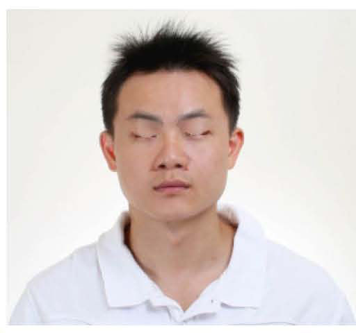
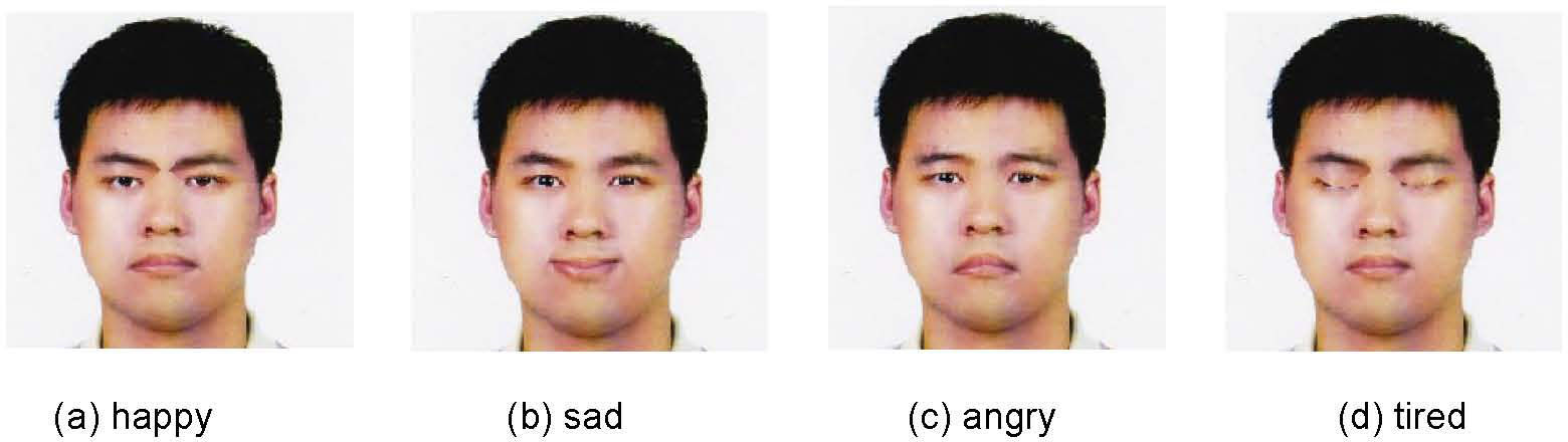
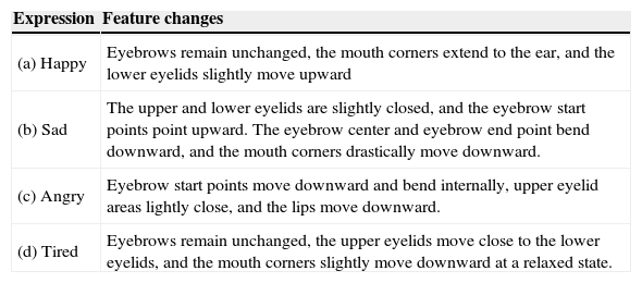
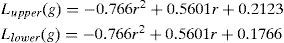
The eyebrow, eye, and mouth deformations required for expression have been discussed which is shown in Table 5. By using the new coordinates for image correction in bicubic interpolation processing, the resulting image loaded by the system captures the FP coordinates and stores the FPs until the next image is loaded or when the interface is closed. After image loading, the user may continuously operate or manually select the expression changes and facial expression generation buttons to generate different results. The expressions automatically generated by the system are shown in Figure 11.
Feature changes in facial expressions.
| Expression | Feature changes |
|---|---|
| (a) Happy | Eyebrows remain unchanged, the mouth corners extend to the ear, and the lower eyelids slightly move upward |
| (b) Sad | The upper and lower eyelids are slightly closed, and the eyebrow start points point upward. The eyebrow center and eyebrow end point bend downward, and the mouth corners drastically move downward. |
| (c) Angry | Eyebrow start points move downward and bend internally, upper eyelid areas lightly close, and the lips move downward. |
| (d) Tired | Eyebrows remain unchanged, the upper eyelids move close to the lower eyelids, and the mouth corners slightly move downward at a relaxed state. |

This study used the skin color distribution method for skin color segmentation. However, skin color in a color image is subject to the influence of race and light intensity. In a well-illuminated face image, the skin color area with a face can generally be identified. Full skin color areas can be segmented in cases of the yellow and white race. However, in case of low skin color brightness caused by relatively white, black, or red skin color or a weak light source, most of the facial area cannot be accurately segmented. When a large number of face blocks are left out, noise filtering and area filling can hardly retain the completeness of the face in subsequent face positioning. During skin color segmentation, if any area in the background is similar to the skin in color, a large area of blocks will be present in the background when the light source is bright. As a result, the background, rather than the face area, is retained in the selection of the maximum continuous area using the connection-object method. To address the problem, in the face and neck segmentation step, in addition to removing the pixels outside the oval, the percentage of pixels judged as skin color inside the oval is tested. If the number of skin color pixels is too low, the area is not the face area. Labeling statistics are then used to determine the candidate areas in descending order of labels.
Lip color and skin color segmentation are similarly influenced by the brightness of the light source. Thus, accurate positioning of the lip becomes difficult through lip color segmentation results because the lip line is a relatively apparent edge.
The experimental results suggest that the mouth corner can be easily detected by Canny edge detection. However, the detection results of the upper and lower edges of the lip are unsatisfactory. Mouth Map should thus be used to enhance the capturing of other FPs to limit the area of the mouth corner. With regard to mouth deformation, the movement mainly affects the mouth corner. When the two mouth corners do not deviate from the lip line, the remaining FPs become inaccurate. This process has a certain level of robustness in completing the deformation of the expression. After a simple relative position adjustment, the accurate position the deformation effects on the lips can be generated.
The proposed image deformation algorithm can also generate the deformation of the surroundings of the image at any position because the deformation area is unaffected by the relative position of the original image. For example, in the forehead, the coordinates of the upper and lower points are set by the eyebrow start points and eye aspect ratio, and the coordinates of the upper, lower, left, and right points of the mouth are used as the original image coordinates of the eyes to segment the four FPs of the eye into two triangles for transformation calculation. The results suggest that eye transformation can be generated in the specified forehead and mouth. Such transformation does not require calculating the displacement from eye to forehead or mouth. The process can be realized by changing the original image coordinates when calculating the two eye triangles.