


Progressively deeper and hotter oil wells have driven design modification that enhances the performance in sensors and downhole electronic instruments. Oil reservoirs in Mexico are located at mean depths of 6,000m; as a consequence, the requirements for measuring thermodynamic and geophysical parameters are challenging. This paper describes a bidirectional communication system that exchanges data from a down-hole high pressure and high temperature (HP/HT) measurement tool to the surface installation. The communication medium is a 7km mono-conductor 1K22 logging cable used also as a power supply transmission line. The system consists of a proprietary downhole measurement tool, composed of a HT/HP sensor and a high temperature DSP-based electronic device, and a data acquisition equipment located in the surface installation. The system employs a communication algorithm that automatically changes the carrier frequency of the modulation technique employed, to avoid issues derived from noise interference, cable attenuation and thermal drift of the front end passive elements. The laboratory tests results provide a firm basis for testing and evaluating the system in the field.
La extracción de hidrocarburos se realiza en fondos de pozo cada vez más profundos y calientes, lo cual ha impulsado modificaciones en los diseños de sensores e instrumentos electrónicos que se utilizan en estas aplicaciones para mejorar su rendimiento. Las reservas de petróleo en México se encuentran a profundidades promedio del orden de 6 000m; por lo consiguiente, los requisitos para la medición de parámetros termodinámicos y geofísicos son un reto tecnológico. Este documento describe un sistema de comunicación bidireccional que intercambia información entre una herramienta de medición de alta presión y alta temperatura (HP/HT), ubicada en el fondo del pozo, y un equipo de medición instalado en la superficie. El medio de comunicación es un cable mono-conductor de 7km tipo 1K22 usado para descender la herramienta, el cual también se usa como una línea de transmisión de la fuente de alimentación. El sistema de comunicación consta de una herramienta de medición en fondo de pozo, la cual cuenta con solicitud de patente, y está compuesta de un sensor HP/HT, un dispositivo electrónico de alta temperatura basado en DSP y un equipo de adquisición de datos situado en la instalación de superficie. El sistema emplea un algoritmo de comunicación adaptativo que cambia automáticamente la frecuencia de la portadora de la técnica de modulación seleccionada, para evitar los problemas derivados de la interferencia de ruido, la atenuación del cable y de la deriva térmica de los elementos electrónicos. Los resultados obtenidos en las pruebas de laboratorio proporcionan una base firme para la prueba y evaluación del sistema en campo.
The need for measuring and registering oil reservoir's characteristics has motivated the development of high temperature measurement tools employing specialized electronics and novel communications systems [1]. Oil well data logging state of the art use the electrical cable connections for communications as well as electrical power energy distribution media to supply down-hole electronics and tools.
Different bi-directional communications techniques have been published for down-hole measurements. Communication techniques range from simple baseband data transmission to sophisticated techniques as spread spectrum Code Division Multiple Access (CDMA) [2–6]. The referred communications systems do not specify an adaptive bi-directional transceiver, using a monoconductor coaxial cable as communication channel, which incorporates an automatic carrier frequency adjustment of the modulation technique employed for data transfer or adjustable filters for separating the transmission and reception carrier's frequencies.
These communications systems do not include a system capable of measuring the transmission and reception attenuation effect of signals in order to determine the best carrier frequencies for successfully transferring data in a highly attenuating medium. As a final point, these communications systems do not incorporate a method for performing signal characterization in real time of a corrosion resistant monoconductor cable such as the 1K22, as well as the signals attenuation produced by thermal drift of passive elements by generating test tones modulated by different techniques and the estimation of the signal to noise ratio (SNR) of the communications channels.
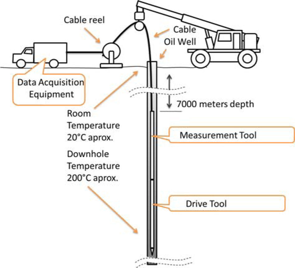
2Experimental setupThe down-hole measurement system is comprised by a Data Acquisition Equipment (DAE) located at the surface installation, a logging cable and a HP/HT measurement tool located at the bottom of the oil well as depicted in figure 1.

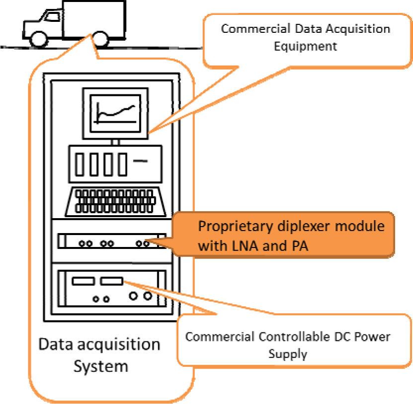
Control of the system is performed in a LabView® application that is implemented in the DAE, which includes a proprietary diplexer module and an AC or DC high power supply as illustrated in figure 2. The DAE utilizes a 1K22 logging Mono-Conductor cable not only for supplying energy remotely, but also to communicate in a bi-directional form to the down-hole electronics measurement tool.
3Expected problems
There are several problems in the implementation of a down-hole electronic instrument; however, for the communications system the main issues could be generated from: cable attenuation, thermal noise, wide thermal drift of passive elements and finally the reduced diversity of high temperature electronic devices available on the market.
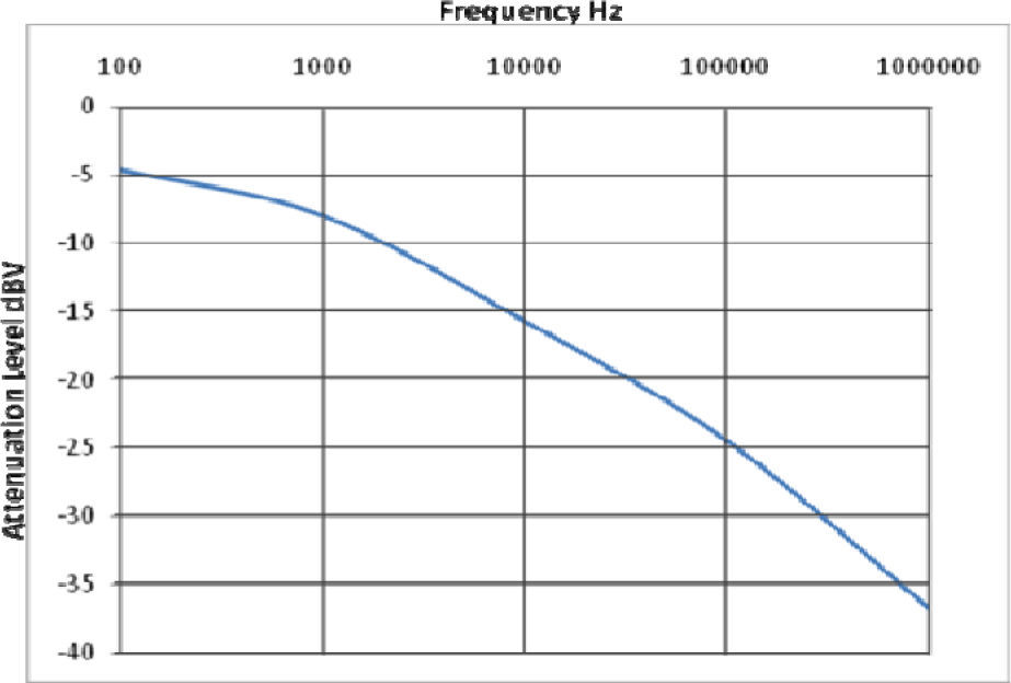
3.1Cable attenuationSignal attenuation, caused by the monoconductor 1K22 cable characteristics and environmental conditions, is the main obstacle to overcome for signal communication between the data acquisition equipment and the down-hole measurement tool. The 1K22 cable manufacturers provide important electrical and mechanical parameters. The degree of attenuation depends on the frequency of the communications carrier and the four electrical characteristics of the cable which are: electrical resistance of inner conductor and armor, distributed capacitance between them, the distributed inductance and conductance of the isolation material. A graph of attenuation vs. frequency has been obtained as shown in figure 3. The performance of the communications link is dependent of the modulation technique chosen for data transmission and the selected carrier frequency.
3.2Thermal drift of passive elements")
Thermal drift is a significant issue to take into account when designing for high temperature applications. High temperature gradients affect the communication circuits due to frequency response drift of the transmission and front-end filters in the reception where a stable tuning is desirable. Filters can be analogue, passive or active, or digital. Analog active filters have been avoided because of their high noise generation which would negatively affect the SNR at the receiver reducing its performance. Passive filters have been selected in the receiver design; however, they are sensitive to temperature changes when are implemented with discrete capacitors and inductors. These filters are key components that handle the transmission and reception of signals. In contrast, digital filters are practically immune to temperature changes as the case of digital filters. In this application, a combination of analog passive and digital filters has been implemented.
3.3High temp electronics componentsConsidering a design perspective, a reduced high temperature (200°C) set of components is available in the market, with a few electronic devices that can withstand the harsh high temperature environment. Despite this, the supply of these components is growing and today it is possible to find high temp digital signal controllers (DSC), regulators, MOSFETs, as well as wide range values of passive elements.
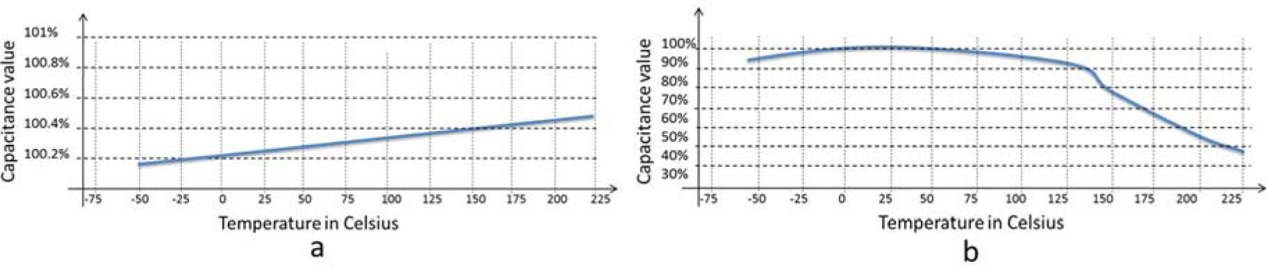
3.4High temperature passive componentsIn order to handle a very wide range of signal magnitudes, filters are based on discrete high temperature inductors and capacitors. The thermal drift of the inductors is small, it is in the order of 1% from 25°C to 200°C, and the DCR tends to double its value at 200°C. However, capacitors have a large thermal variation and cause the thermal drift of the frequency response of the passive filters. Figure 4 shows the capacitance change for two commercial dielectric materials.
 Capacitance change of XHT dielectric capacitors, b) Capacitance change of NPO dielectric capacitors from Presidio components Inc")
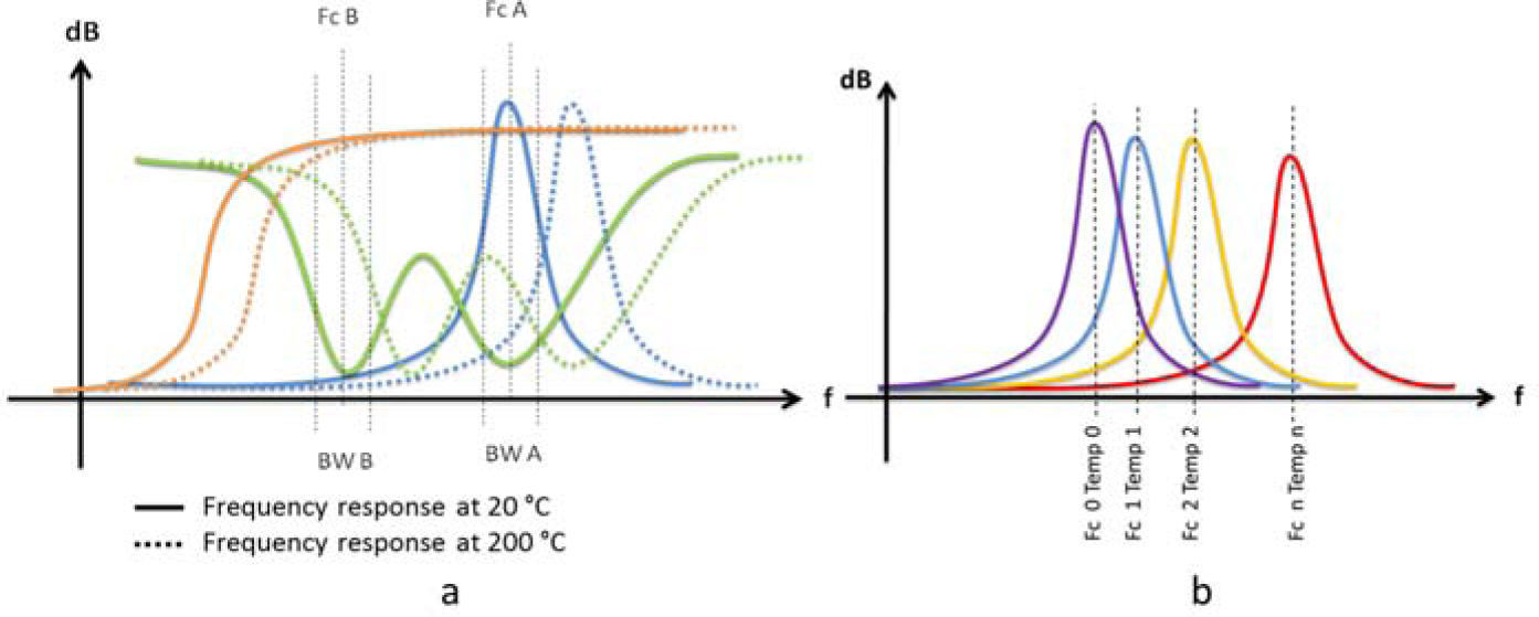
It is evident that choosing a NPO dielectric capacitor would significantly reduce the thermal drift effect; however, the problem with this type of devices is their limited capacitance values at reasonable package sizes. For example an XHT capacitor device can have a maximum capacitance of 1800pF when a same size NPO capacitor can have just 100pF [8]. Because of size convenience, XHT capacitors have been chosen for the design of filters although its capacitance value drops around 50% when reaching 200°C. This means that the drift of all filters have the same displacement, which makes possible to have them always tuned to the same frequency. This is better described in figure 5.
 Expected thermal drift of down-hole instrument's communications module's. b) Laboratory characterization of down-hole tool's front-end band pass filter related to temperature")
In figure 5a, the orange curve represents the response of a high pass filter, the blue curve represents the response of a band pass filter and the green represents the admittance of a wave trap. FcB and FcA are the centre frequencies of the two carrier communications signals and BWB and BWA are the bandwidth of each channel.
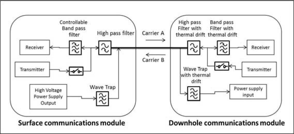
4Description of hardwareDue to the high temperature gradients encountered in down-hole data logging, the down-hole tools are built using high-temperature electronics parts to support an operating temperature up to 210°C. The electronic systems are protected by a titanium enclosure which supports a working pressure up to 22000psi. Each tool is attached together by section dividers which perform the physical and electrical connections of the modules. Besides, the data acquisition equipment is composed by a proprietary industrial grade electronics diplexer module, as well as commercial data acquisition equipment and a remote controllable power supply (see figure 2). The communication medium (1K22 Cable) is also used as a power transmission line; a Power Line Communications (PLC) [7] scheme has been implemented as shown in figure 6.

The selected frequencies for communicating the system are 20kHz (for sending data from the down-hole tool to data acquisition equipment) and 30kHz (for sending data from the data acquisition equipment to the down-hole tool). These frequencies have been chosen regarding a tradeoff between the attenuation level of the 1K22 cable that increases with frequency and the size of passive elements needed to handle low frequencies.
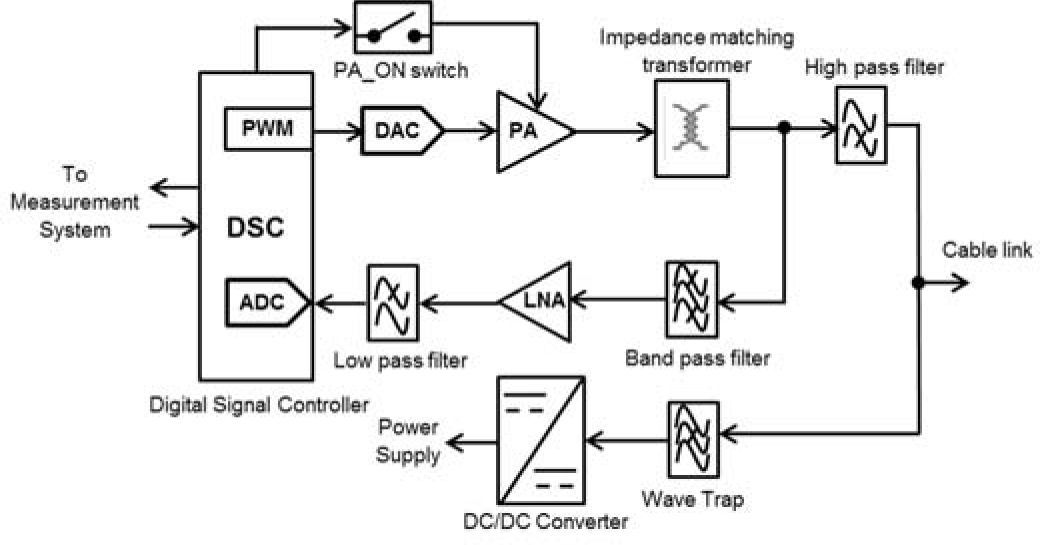
4.1Downhole communications moduleThe down-hole instrument has been designed based on a high temperature DSC, which is responsible of several tasks, such as reading data from pressure and temperature sensors as well as storing them in a non-volatile memory. There are two DSC in the down-hole instrument, one controls a measurement tool and the other controls a drive tool as depicted in figure 1. However, the DSC based module that establishes the communication with the DAE at the surface is the measurement tool. The block diagram of the communications hardware applied to the measurement tool module is illustrated in figure 7.

The high pass filter rejects all low frequency signals in order to decouple the power supply impedance and couples the transmission signal to the power line cable. The band-pass filter is responsible of attenuating the non-desirable signals out of the reception bandwidth, in order to provide the maximum signal level, at the Low Noise Amplifier (LNA) input. The LNA amplifies the communications signal to a level detectable by the Analog to digital converter (ADC) integrated in the DSC, which finally carries out the demodulation of the signals to recover the message and executes the instruction command. The LNA is an amplifier that produces very low noise itself; however, in order to avoid any aliasing at the ADC input, a low pass filter is applied between the LNA and the ADC input. The DSC can send messages by two of its Pulse Width Modulated Output Signals (PWM) that are converted to analog signals by a Digital to Analog Converted (DAC) which sends this signal to a Power Amplifier (PA) which finally sends the communications signal trough the impedance matching transformer that efficiently couples the signal to the 50Ohms 1K22 cable impedance. The Power Amplifier On Switch (PA_ON Switch) shuts down the power amplifier to avoid the noise produced by this element to come to the receiver section. Finally, the last element of the modem is the Wave Trap filter which avoid the communications signal to be attenuated or suppressed by the low impedance of the power supply connected to the 1K22 cable. The wave trap presents a high impedance to the communications signals and low impedance to other signals helping to conserve most of the power of the communications signal in the 1K22 cable.
4.2Surface communications moduleThe data acquisition equipment has been designed based on a commercial data acquisition module with analog inputs and outputs attached to a Diplexer device, which is responsible of providing not only the power supply and communications signals to the 1K22 cable, but also to carry out the recovery and conditioning of the communications signal to be detected by the data acquisition module.
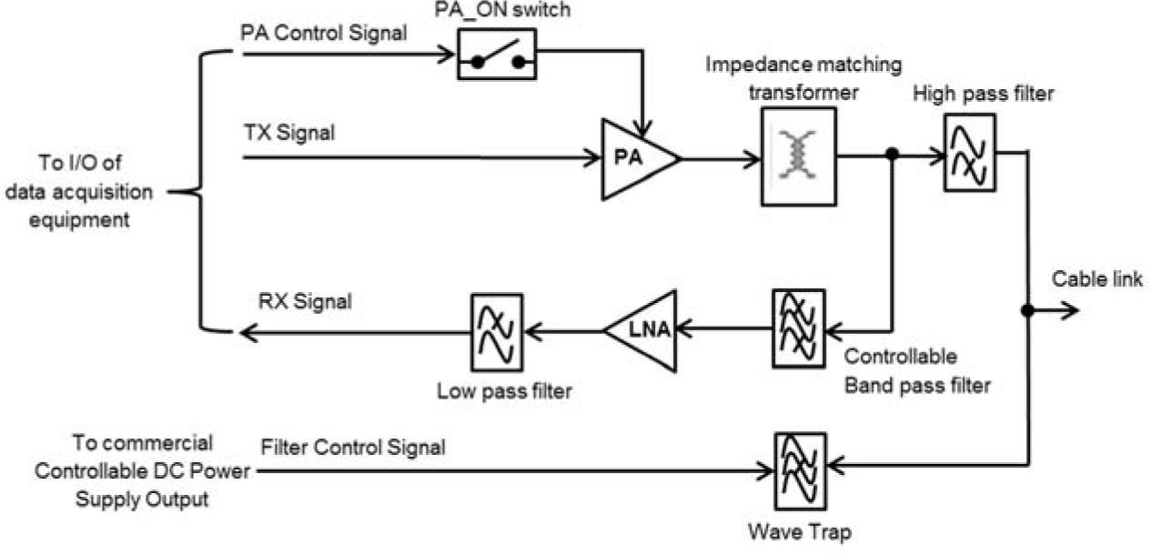
The operation of the diplexer module and the high voltage power supply is controlled by the data acquisition module trough control signals. The internal block diagram of the diplexer module is quite similar to the down-hole measurement tool as shown in figure 8.

The controllable band pass filter is necessary for tuning the LNA in order to carry out any change on the received carrier frequency.
5Adaptive communications techniquesThe thermal dependence of signal attenuation and filter tuning drift, leads to the use of adaptive communications techniques in order to guarantee the integrity of the data to be transferred via the high attenuating 1K22 coaxial cable. Two possible techniques where considered in the design to be able to track the central frequency tuning. These two techniques are described below.
5.1Dynamic frequency adjustmentThis technique is based on the characterization of the frequency response related to the temperature of the front-end filters; thereby, determining the best carrier frequency to be applied for each temperature operation. The results of the tests are captured in a bi-dimensional data vector that associates the best values of carrier frequency with a given down-hole tool's operating temperature. The data vector is loaded into the data acquisition equipment which decides the carrier frequencies to be applied based on the temperature measurement of the down-hole tool.
This is method minimize the effect of thermal drift of front-end filters at the downhole tool because carrier frequencies are chosen based on laboratory trials of true response of filters in a given operating temperature condition. The drawback of this approach is that it cannot predict other parameters that affect the communications link, such as the noise levels or the attenuation behavior of the 1K22 cable in field tests.
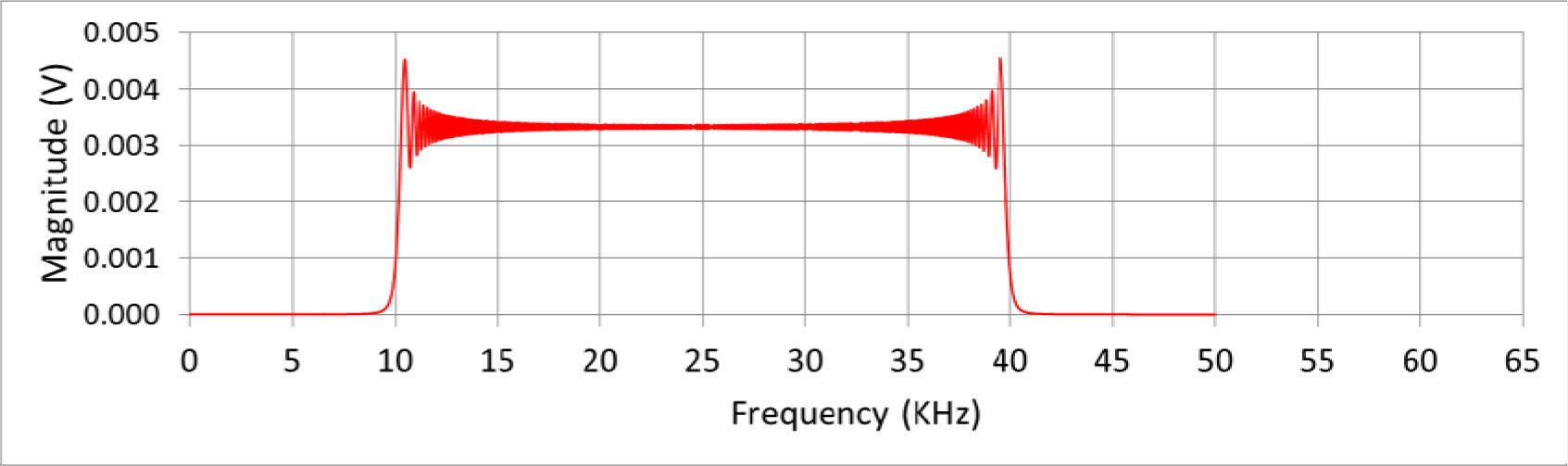
5.2Real-Time characterization of communications medium and filter responseA different method based on a dynamic characterization of the communications medium is proposed. In this approach, all effects of the parameters that can affect the communications link are tested together in real time. To carry out this characterization, a procedure is applied when the data acquisition equipment sends a communications calibration command to the down-hole tool, which enters in the receiver calibration mode to perform some measurements of its receiver's communications channel, while the data acquisition equipment sends a pulse consisting in a set of frequency steps to sweep from minimum to maximum of the desired frequency band. All frequency steps have the same duration, which are detected by the receiver in order to obtain the frequency value that has the best SNR for receiving data. This frequency configuration was used in the laboratory trials. The test signal contain the following characteristics: initial frequency (10kHz), final frequency (40kHz), step frequency (10Hz) and number of steps (3000). Figure 9 shows the frequency response of this pulse signal.

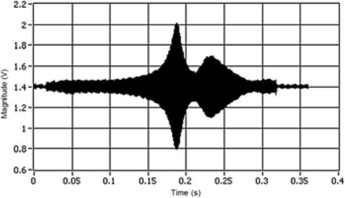
The test signal that sends the transmitter passes through the entire communications medium, i.e. the power amplifier, the impedance matching transformer, the high pass filter as well as the wave trap connection node. Then the signal make its way through the 1K22 cable, the receiver's wave trap node, high pass filter, band pass filter and low noise amplifier before reaching the receiver's inputFigure 10 depicts the received signal in time domain at the receiver's input.

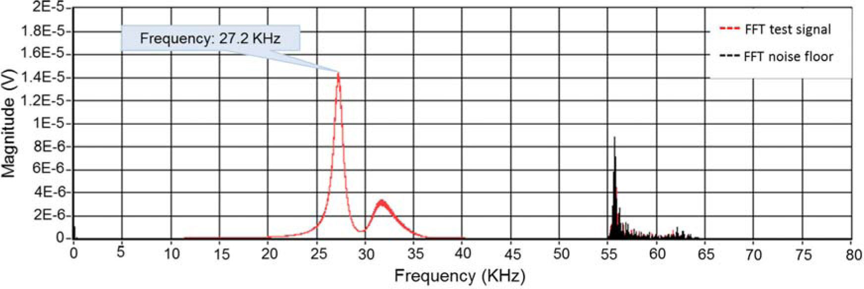
On the other hand, when receiving the noise floor signal, this signal is a combination of all noise sources that come from almost everywhere from the medium. The most significant signals also pass through all the front-end filters of the receiver, even though some thermal noise is also generated by the DSC close to the receiver's input. Both received signals that have been deformed through their path are sampled and stored for posterior processing. This process consists basically in obtaining the spectral power of the sampled signal by performing a Fast Fourier Transform (FFT), which generates data vectors that represent the power of the signal in frequency domain [9]. These data vectors are named the carrier vector and the noise vector. The final process is to obtain a data vector with the best SNR, whose highest value indicates the best carrier frequency to communicate data as shown in Figure 11. In this trail the yielded results depicted a frequency of 27.2kHz at 23°C.
6Adaptive communications techniques
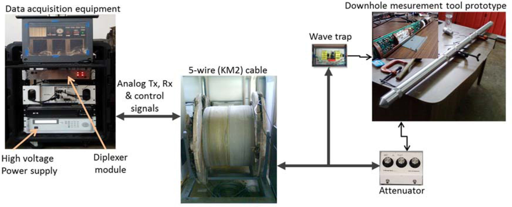
Some tests have been performed using an industrial grade prototype in the laboratory in order test the performance of the communications system of the down-hole measurement tool. For this purpose a 7km, 5-wire KM2 cable have been used as the communications channel to simulate the final 2-wire coaxial 1K22 cable. The experimental setup is shown in the Figure 12.

The cable attenuation is 40dB at room temperature, and additional attenuation was used to simulate the effect of temperature on the cable, with a commercial attenuator in steps of 10dB up to 70dB. A set of communication commands were sent through the cable to determine the sensitivity of the receiver. The attained results were successful above 110dB attenuation.
7ConclusionsDeveloping a down-hole instrument capable of communicating data through large and high attenuating logging cables is a challenging task. The high noise levels added to the narrow variety of high temperature electronic devices make this work more difficult. Several techniques that range from simple baseband data transmission to sophisticated techniques like spread spectrum Code Division Multiple Access (CDMA) have been developed. However, none of these techniques describe an adaptive communications system that characterizes the communications medium in real time in order to guarantee the bidirectional communications link. The proposed method based in sending tests signals in real-time is promising. The attained laboratory results have shown that the configuration of the proposed communications system performs very well, taking to the authors to the next stage of the work, which is to carry out a technological test in the field.
This research is part of the project number 137547, supported by the program CONACYT-SENER-HIDROCARBUROS. The authors wish to express their thanks to the Electrical Research Institute (IIE), CONACYT and PEMEX for supporting this work.