


In this study, effective strain is evaluated for large simple/pure shear deformations and new expressions are derived. The validity of these relations was checked by numerical calculations. In addition, finite element analysis of simple shear and pure shear modes of deformation was conducted using ABAQUS software. Additionally, two other major expressions for evaluating effective strain at large simple shear deformation were investigated and compared with finite element results. Based on FEM results, the linear relation between shear strain and effective strain large strains shall be replaced with the logarithmic one. It is also found that for the same amount of shear strain, a higher value of effective strain is accumulated in the material when it is deformed through simple shear rather than pure shear.
Simple shear and pure shear are considered as the most important modes in deformation of materials. While pure shear is an ideal deformation mode in metal forming operations (Segal, 1995), simple shear is considered as an optimal mode of deformation for grain refinement via severe plastic deformation (SPD) (Segal, 2002, 2006). Generally, most SPD techniques benefit from shear deformation of materials. In some techniques like equal channel angular pressing (ECAP) (Valiev & Langdon, 2006), high pressure torsion (HPT) (Zhilyaev & Langdon, 2008), twist extrusion (TE) (Beygelzimer, Varyukhin, Synkov, & Orlov, 2009) and simple shear extrusion (SSE) (Pardis & Ebrahimi, 2009), simple shear is a dominant mode of deformation while some other methods like pure shear extrusion (PSE) (Eivani, 2015) and accumulative channel-die compression bonding (ACCB) (Kamikawa & Furuhara, 2013) are based on pure shear deformation. In addition, in some other techniques such as cyclic extrusion-compression (CEC) (Richert & Richert, 1986) and cyclic expansion-extrusion (CEE) (Pardis, Chen, Ebrahimi, Toth, Gu, Beausir, & Kommel, 2015; Pardis, Chen, Shahbaz, Ebrahimi, & Toth, 2014; Pardis, Talebanpour, Ebrahimi, & Zomorodian, 2011) the two deformation modes (simple and pure shear) are both active. Since all of these SPD methods deal with giant straining of materials, the amount of accumulated equivalent strain can be considered as a suitable factor for comparing the degree of SPD imposed by these different techniques. Therefore, relations which convert shear strain to its equivalent effective strain are of great importance. This fact becomes even more important when considering the increasing interests on SPD processing of materials as well as development and modifications of various SPD techniques. However, fewer studies have been devoted to the basic relations between shear and equivalent strain values. In this study, these relations are reconsidered and investigated by finite element method (FEM). In addition, new expressions are presented for evaluation of effective strain at large shear deformation and their validity is examined by FEM. The results can be applied to estimate the accumulated strain after processing the samples by any specific forming/SPD technique. Before that, however, it is needed to determine the dominant deformation mode. In this regard, the kinematically admissible velocity field proposition for a given deformation process can make it much easier for considering simple shear/pure shear deformation modes in some techniques like Axi-symmetric forward spiral extrusion (Khoddam, Farhoumand, & Hodgson, 2011) and Vortex Extrusion (Shahbaz, Pardis, Ebrahimi, & Talebanpour, 2011; Shahbaz, Pardis, Kim, Ebrahimi, & Kim, 2016) where such classification might not be easily possible.
2Effective strain at large shear strains2.1Simple shearGenerally, there are two main expressions for evaluating the equivalent strain at large simple shear deformation. Shrivastava, Jonas, and Canova (1982) suggested the following common equation for evaluating nominal equivalent strain at large simple shear deformation.

However, Polakowski and Ripling (1966) stated Eq. (1) would not be valid at large shear strains as the directions of the maximum normal stress and strain are not coincident in simple shear deformation and derived the following Eq. (2):
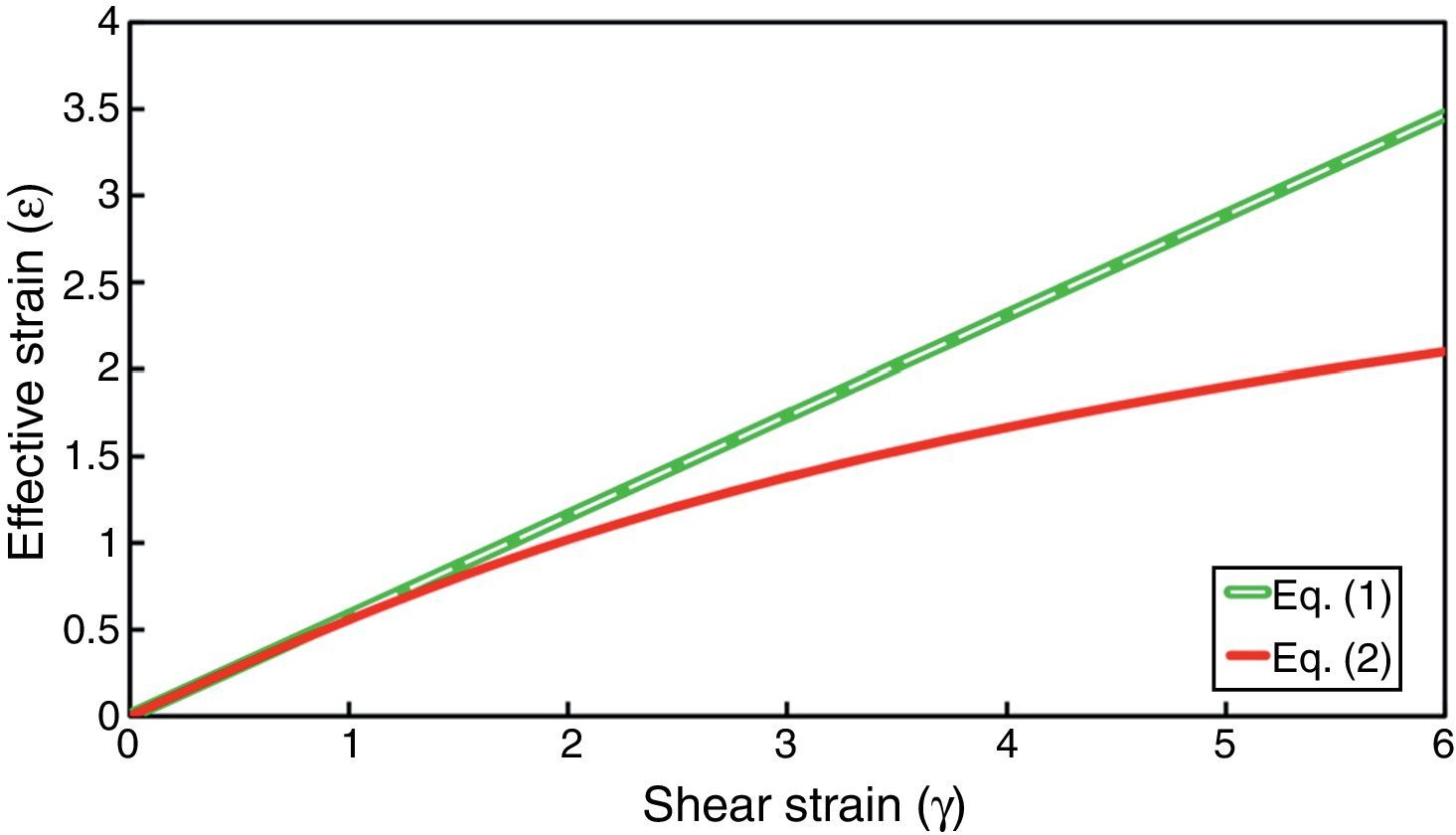
This equation had been previously proposed by Eichinger (1955). Furthermore, there are records on a similar expression presented by Nadai (1937) for evaluating octahedral shear strain in simple shear deformation. However, the resulting values of these two major expressions would be significantly different at high shear strain values as illustrated in Figure 1.
 and (2).")
Illustration of the equivalent strain as a function of shear strain calculated by Eqs. (1) and (2).
According to Figure 1, these two equations are nearly coincident at relatively low shear strains (γ<2). However, at higher shear strain values, the difference between the resulting equivalent strain values from these two relations becomes significant. Therefore, based on the increasing number of studies conducted on severe straining of materials by SPD, these relations should be reconsidered as the difference between them cannot be ignored.
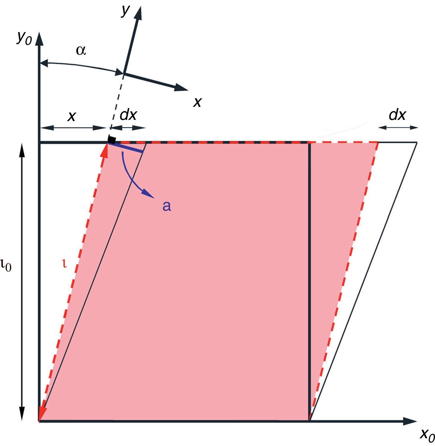
In our approach to evaluate equivalent strain for simple shear deformation, we consider a square of side length l0 deformed by simple shear into a parallelogram (Fig. 2).

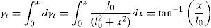
At this point, the amount of shear strain is defined by γ=x/l0 which is based on the initial side length (l0) and therefore, can be entitled as “engineering shear strain”. However, it would not be correct to use this relation for any additional increments of shear deformation as the geometry has been changed to a parallelogram. Therefore, we introduce a new term (γt) called “True simple shear strain” which is based on the current geometry dimensions and is defined as follows:
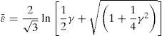
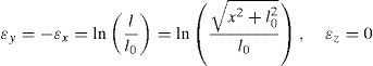
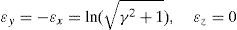
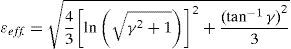
Integrating Eq. (3) yields:Meanwhile, during simple shear deformation, an element of length (l0) elongates to (l) and the corresponding strain components would be calculated as Eq. (5).Considering simple shear deformation of a square of unit length (l0=1), previous equations can be simplified to:Substituting Eqs. (6) and (7) into Mises criterion, the equivalent strain for simple shear mode of deformation can be calculated as follows:2.2Pure shear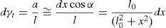

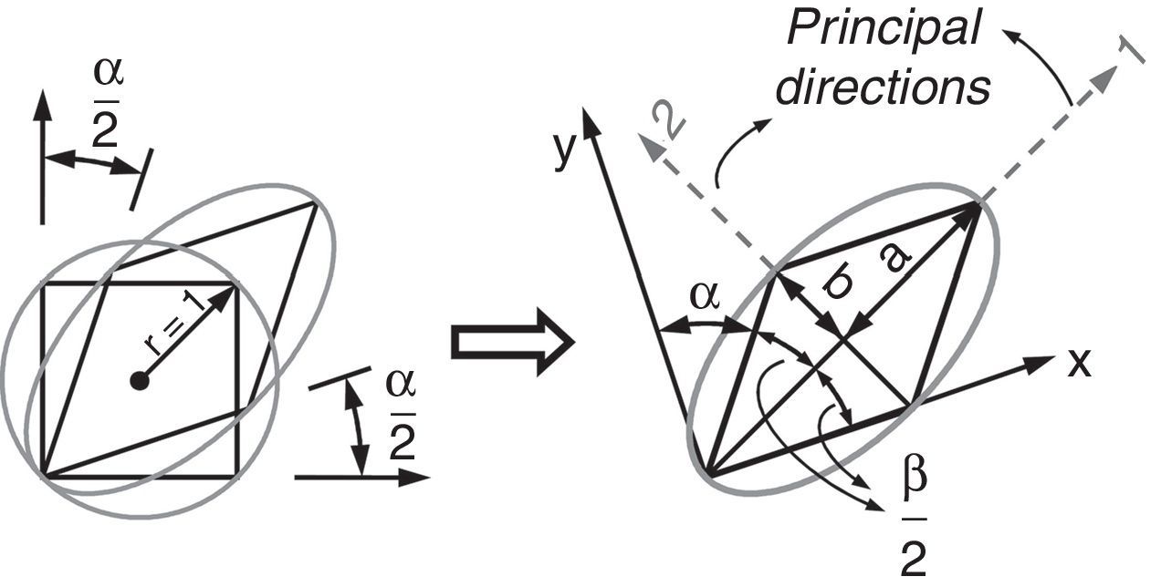
To evaluate equivalent strain in this mode, we can consider a square inscribed in a circle of unit radius. Deforming such geometry through pure shear changes this circle to an ellipse with major and minor diameters of 2a and 2b, respectively which are the principal strain directions (Fig. 3).

Due to volume constancy and plane strain conditions, the area of this circle remains constant during deformation process. Therefore:


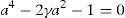
Similarly, the initial square element deforms to a parallelogram illustrated in Figure 3 and the following statement can be written:
where,Therefore:
Using this statement, shear strain can be expressed as follows:
Therefore:which results in:Due to plane strain condition, the state of strain can be defined as follows:
According to Mises criterion the equivalent strain value for pure shear mode of deformation can be calculated as follows:
3Numerical calculations
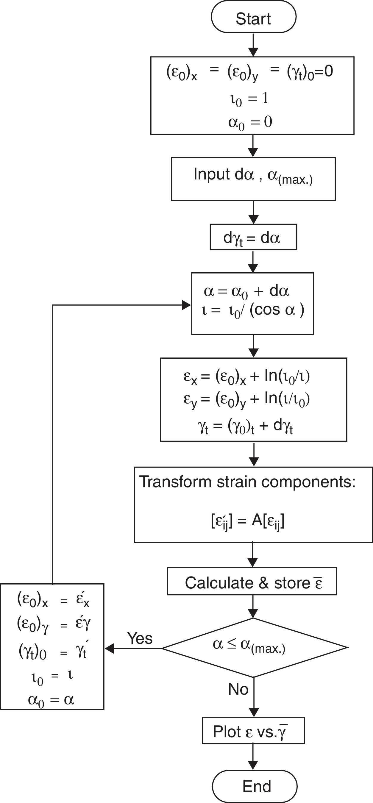
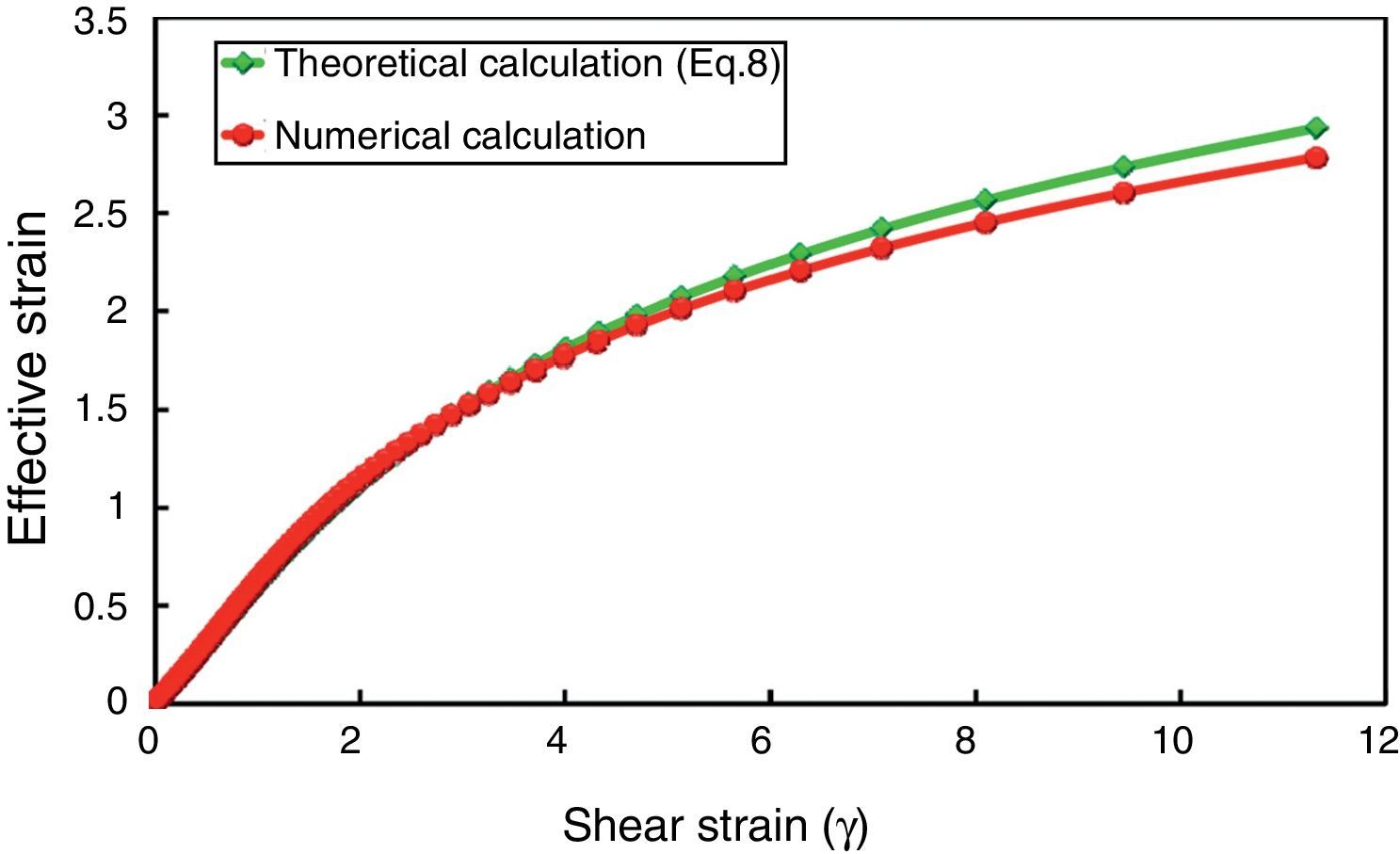
Unlike pure shear deformation mode, the orientation of principal axes rotate during simple shear deformation (Canova, Shrivastava, Jonas, & G'Sell, 1982), which is not considered in the previous part on theoretical calculation of simple shear. To examine the probable error caused by ignoring this fact, numerical calculations were performed. Calculation steps are illustrated as a flowchart in Figure 4.

In these calculations, a constant incremental distortion angle (dα) is considered for each deformation increment and calculation loop is continued until the final predetermined deformation state, with maximum distortion angle of αmax. with respect to vertical axes, is reached. The values in numerical calculations were considered to be dα=1° and αmax.=80° for this investigation. Simple accumulation of strain components at subsequent incremental deformation steps results in a graph which is equivalent to what is predicted by Eq. (8). However, in numerical calculations we considered the incremental rotation of axes between each consecutive step and the results are illustrated in Figure 5. This calculation was performed at each deformation increment by transforming the strain components of the previous step by (dα) and summing the transformed values with the strain components of the current incremental simple shear deformation.
) and numerical calculation results for simple shear deformation.")
Comparison of theoretical (Eq. (8)) and numerical calculation results for simple shear deformation.
Figure 5 compares the result of numerical calculation with that of theoretical calculation (Eq. (8)). Although rotation of axis is considered in numerical calculations, the result would not deviate significantly from the result of Eq. (8) (which does not consider transformation of strain component). Therefore, Eq. (8) would be valid for determination of equivalent strain in simple shear deformation.
4Finite element analysis procedureThe commercial finite element code, ABAQUS/Explicit, was used to simulate simple shear and pure shear modes of deformation. Due to the plane strain nature of these deformation modes, simulations were performed in 2D condition. Commercially pure aluminum was selected for finite element analysis. In order to eliminate the effect of work hardening on the results, the material was considered to exhibit perfect plastic behavior with 35MPa yield stress. Moreover, to reduce the effect of friction on the deformation behavior of material, frictionless condition was considered in this study. All of these considerations make it possible to investigate the effect of deformation modes only, while eliminating the effect of all external parameters on the results.
The sample was considered to be a square of 10mm side and was meshed with 4-node bilinear plane strain quadrilateral elements (CPE4R) (ABAQUS & Manuals, 2002). The boundary conditions applied in simulation process will be described in the following sections.
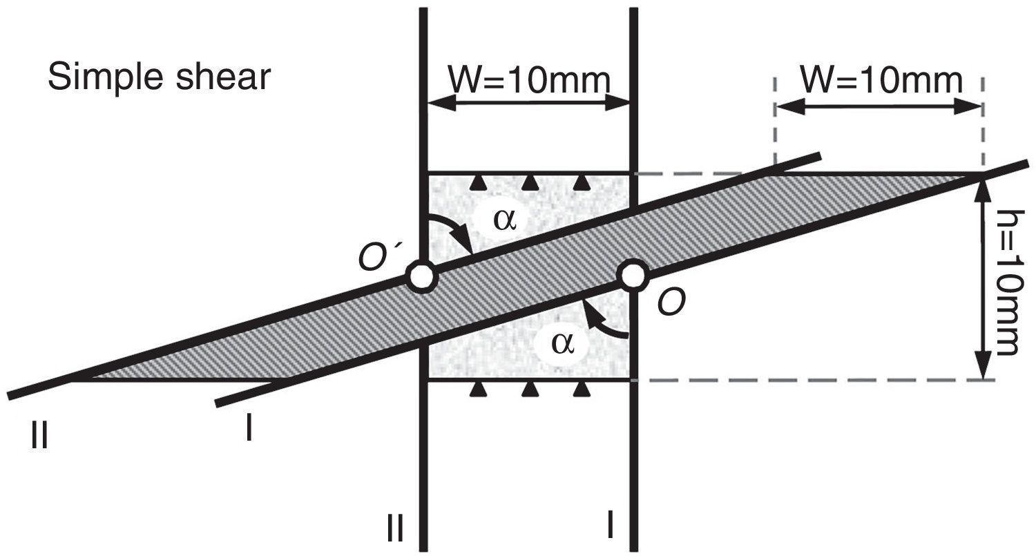
4.1Simple shear deformationTo simulate simple shear mode of deformation, the movement of elements along the top and bottom sides of the sample were constrained in vertical direction. The two other sides were constrained with two dies (I and II) which were fixed at O and O’ for any translational movements (Fig. 6). However, these dies (I and II) were given only one degree of freedom to be able to rotate in the same sense through a predefined value about points O and O’, respectively. The position of these points were considered in the middle of the left and right sides of the sample and the maximum rotation angle was considered as α=80° which would result in a shear strain of γ=tan(80)≈5.7. Such geometrical assembly and boundary conditions are illustrated in Figure 6 which are similar to deformation conditions in the cross section of samples deformed through simple shear extrusion (SSE) (Pardis & Ebrahimi, 2009).

During deformation of the sample through the illustrated assembly in Figure 6, the sample area remains constant and such setup almost guarantees the simple shear mode of deformation which is stated by Segal as an effective mode of deformation in severe plastic deformation (SPD) for grain refinement (Segal, 2002, 2006).
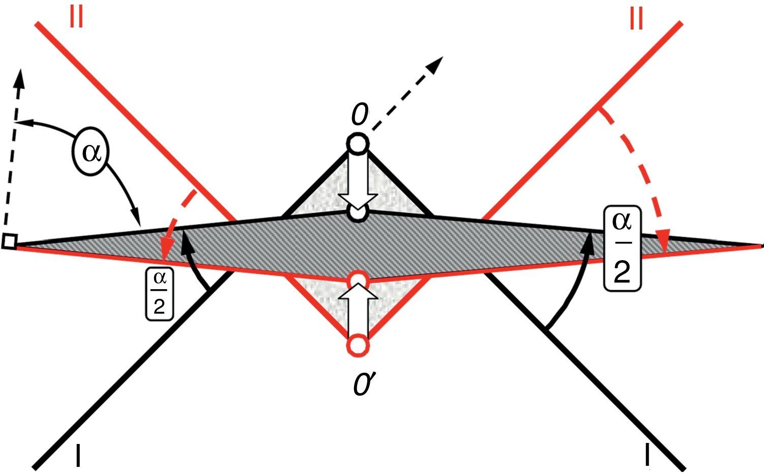
4.2Pure shear deformationThe assembly setup used in finite element analysis of pure shear mode of deformation is illustrated in Figure 7. In this case, the sample was constrained with two set of dies (nominated by I and II in Fig. 7). Rotating about O and O′, each set (I and II) was shifted toward each other so that the sample area remained unchanged (Fig. 7). The final rotation angle of each die was (α/2) and the total shear angle for the analysis of pure shear was considered to be α=80°, which would again result in a shear strain of γ=tan(80)≈5.7.
5Results and discussion
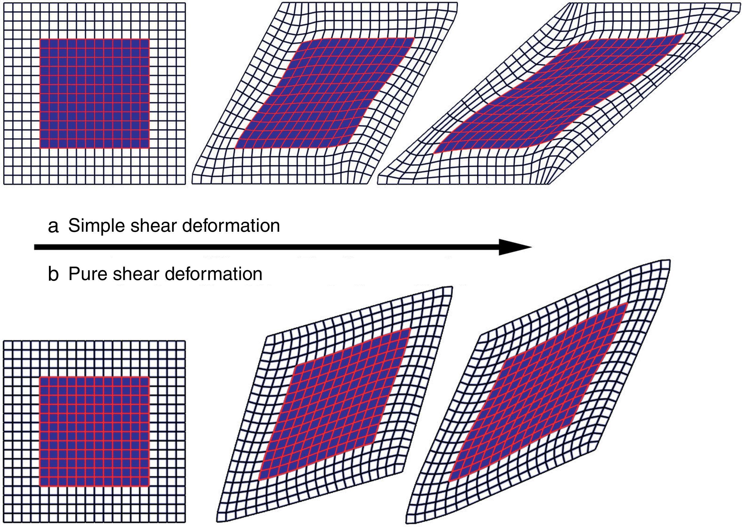
Examples of deformed shape of elements during deformation for both simple/pure shear modes are illustrated in Figure 8.
 simple shear and (b) pure shear.")
Inhomogeneous deformation of elements is seen at the borders. Moreover, the deformation mode at these areas is neither simple shear nor pure shear. Therefore, the inner region of the meshed sample (highlighted area in Fig. 8) was considered for data extraction and the average value of effective strain in the selected elements was recorded (from FEM results) for further investigations. Such selection of elements would eliminate the mentioned effect of deformation inhomogeneity near the boundaries. Knowing the shear distortion angle at each step during the simulation (αcurrent), the imposed shear strain was calculated by γ=tan(αcurrent) for simple shear and γ=tan(2(αcurrent/2)) for pure shear mode. The calculated value for each step was used to trace the relation between the imposed shear strain and its corresponding average value of effective strain (ε¯) in the selected elements obtained by finite element analysis (Fig. 8).
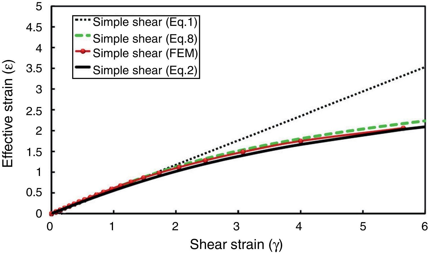
Figure 9 illustrates simultaneous plots of Eqs. (1), (2), (8) and also the finite element result for simple shear mode of deformation.
, (2), (8) and FEM.")
Comparison of the equivalent strains given by Eqs. (1), (2), (8) and FEM.
For γ<2 all equations result in nearly the same values. However, for higher values of γ, (γ>2), the strain values from these expressions deviate significantly (Figs. 1 and 9) which is due to the differences in the principles used in their derivation. Eq. (1) is based on definition of conventional shear strain and von Mises strain while Eq. (2) is calculated using the Hencky strain criterion and Eq. (8) is based on a new term defined as true simple shear strain which was applied in Mises criterion. As can be seen from Figure 9, similar values are predicted by Eqs. (2) and (8) and the curve obtained from finite element analysis is very close to the values provided by these equations.
According to the analytical and FEM results of this paper (Fig. 9), when a material is deformed through simple shear, the effective strain reaches a saturation value which has been introduced as (¿m) by Beygelzimer, Valiev, and Varyukhin (2010) beyond which, it is believed to be no changes in the grain size. Based on such experimental observations and the resulting hypothesis of double stage deformation in simple shear, they proposed a relation between shear strain and the resulting effective strain for simple shear (Beygelzimer et al., 2010) which is similar to Eqs. (2) or (8) of current paper. A similar relation was also presented by Stüwe (2003). In another work, Zhilyaev et al. (2003) proposed a logarithmic relation which is more close to the results of equations (2) and (8).
However, the linear relation (1) has been widely used in many studies and stated to be the correct (Shrivastava et al., 1982). Recently, the validity of Eq. (1) or (2) at high values of shear strain as well as their analytic derivations have become a matter of debate among many researchers. Onaka (2010, 2012) stated that the Hencky strain is an appropriate measure for large deformation and verified Eq. (2) to be the correct one. However, others (Jonas, Ghosh, & Shrivastava, 2011; Shrivastava, Ghosh, & Jonas, 2012) have criticized the Onaka results on applying Hencky formulation to large simple shear deformation and recommended Eq. (1) for evaluation of the equivalent strain in simple shear deformations. In this study and through another approach (numerical and analytic methods) it is shown that Eq. (8) is valid which can be used when monotonically deforming a material through simple shear up to high strain values (Fig. 9). Although such modified relations have been confirmed and was employed by some researchers (Qiao et al., 2014; Zhang, Gao, & Starink, 2010; Zhang, Gao, & Starink, 2011; Zhang, Starink, Gao, & Zhou, 2011), the conventional Eq. (1) is still applied in many studies on large simple shear deformation of materials by SPD.
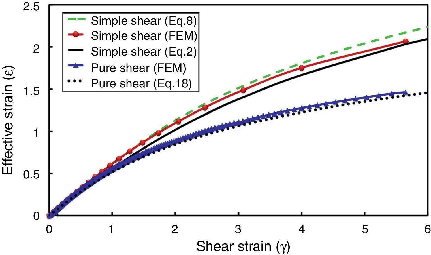
Plots of the relations (2), (8) and (18) are simultaneously illustrated in Figure 10 for simple and pure shear conditions. Meanwhile, the finite element results are also demonstrated in the same figure. It is seen that finite element analysis also confirms the validity of the relation derived in this study for evaluating the effective strain in pure shear mode of deformation. A similar relation has been also reported by Shrivastava et al. (1982) for this mode of deformation which was derived using deformation gradient tensor.

It is seen that less intense strains are accumulated in the material when deformed through pure shear rather than simple shear deformation (Fig. 10). This result is consistent with the idea that simple shear is an optimal mode of deformation for grain refinement through SPD (Segal, 2002, 2006).
6Summary and conclusions- 1-
New relations were derived and presented for evaluating the effective strain in simple/pure shear deformation mode by proposing a new definition as “true shear strain”. The validity of theoretical relation was checked by numerical calculation.
- 2-
Simple and pure shear deformation modes were studied by finite element analysis and the two major relations between the effective strain and shear strain for simple shear deformation mode were investigated. Finite element analysis revealed that the effective strain would have a logarithmic relationship with shear strain when a material is monotonically deformed through simple shear up to high strain values.
- 3-
For the same amount of shear strain, a higher value of effective strain is accumulated in the material when it is deformed through simple shear rather than pure shear.
The authors have no conflicts of interest to declare.
Financial support by the Research Council Office of Shiraz University through Grant number 94-GR-ENG-15 is appreciated. H.S. Kim acknowledges the financial supports by the National Research Foundation of Korea (NRF) grant funded by the Korea government (MSIP) (No. 2014R1A2A1A10051322).
Peer Review under the responsibility of Universidad Nacional Autónoma de México.