


Perlite is an igneous mineral composed by silicon, aluminum, oxygen and water. It can be expanded by heating it up at temperatures above 870°C, then it becomes plastic, and the steam formed inside pressures out of the mineral. Maximum expansion is possible if the particles are heated up quickly, since the expansion degree strongly depends on the remaining water in the particles at the time that they reach the temperature where they become plastic. The typical expansion process consist in pouring the particles in rotary kilns operated with natural gas, but it is proposed in this research that the particles can be heated quickly with microwaves at 2.45GHz. Particles of 0.08cm and 0.018cm of average diameter were expanded 10 to 20 times.
La perlita es un mineral ígneo compuesto de silicio, aluminio, oxígeno y agua. Se puede expander si se le calienta a más de 870°C, entonces se vuelve plástica, y el vapor que se forma en el interior de las partículas de perlita presiona al mineral hacia afuera causando su expansión. La expansión máxima es posible cuando las partículas de perlita se calientan rápidamente, dado que el grado de expansión depende fuertemente de la cantidad de agua que aun esté presente en las partículas al momento que éstas alcanzan la temperatura en que se vuelven plásticas. El proceso de expansión típico consiste en vaciar las partículas en hornos rotatorios que operan con gas natural, pero en esta investigación se propone que las partículas pueden ser calentadas rápidamente con microondas de 2.45GHz. Las partículas de perlita de 0.08cm y de 0.018cm de diámetro promedio se expandieron 10 a 20 veces.
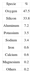
Among the volcanic rocks there is a group, known as rhyolite, compounded by silicon, aluminum, oxygen and molecular water. “Perlite” is a generic name for a siliceous mineral 1 that belongs to this group, and there is a wide range of composition according to the QAPF (Quartz, Alkali feldspar, Plagioclase, Feldespathoid) diagram, and typical composition for perlite is shown in Table 1. It is formed from a magmatic process during lava cooling while in contact with water at high pressures, generating volcanic glass. There are important sources of perlite in mines located in Dikili in Turkey, “No Agua” Peaks in New Mexico, USA, Laguna del Mauele in Chile, and Durango in Mexico. Perlite particles can be expanded, theoretically up to 25 times, by heating under certain conditions of temperature and time, resulting in a highly porous material. Its density, before expansion, is between 2200 and 2400Kg/m3. Perlite is extracted from the mines and crushed down to particles, which are fed in rotary kilns for carrying out the expansion process, then particles become less dense and often change their color from green, pale gray or even black, to white after expansion.
The expansion mechanism consists of heating the particles so that they become soft, due to a glass transition, and water is released, in form of steam, and expands the particle as it boils out of the material. The most appropriate temperatures for expansion are above the glass transition, typically 870°C, and below the sintering temperature, around 1090°C. The composition of the ore affects the softening temperature as well as the melting point, which normally is between 1260°C and 1340°C 1–4. Water that is released below the softening temperature produce particle fracture rather than expansion, then a quick heating for reaching softening temperature is very important for maximizing the expansion efficiency. If particles are heated slowly and all the water leaves the sample before achieving particle softening, then the expansion will be null.
One way for rapid heating of the sample could be increasing the temperature of the kiln, but temperature cannot be above of the melting point of perlite. Thermal conduction coefficient of expanded perlite has been reported between 0.04 – 0.06W/m K 5,6 therefore a high surface temperature does not necessarily result in a faster heating of the inner part of the particles. Indeed, materials with low thermal conduction coefficient exposed quickly to high temperatures result in high thermal gradients.
The aim of this research was performing by quick heating of the particles with microwaves for maximizing expansion efficiency.
2Materials and methods2.1PerliteCrude perlite (CP) for the tests is available from Termolita S.A. de C.V. 7 that extracts the material from its deposits in Durango, Mexico, and then crush it to particles for being expanded and later conform materials such as ultra-light insulating materials for the construction industry, thermal insulation blocks and leveling for roof decks and floor systems, wall finishes and thermal insulation. The most common particle sizes for expansion, and hence the chosen ones for this research, are: coarse, identified as CP-24+30 of 0.08cm average diameter; and fine, identified as CP-40 of 0.018cm. Particles size was measured over a plane, by stereoscopy, considering two dimensions X and Y, the largest one was taken as X; kind of Feret's diameter. Size distribution of the crude perlite particles is presented in the results and discussion section together with the expansion results. Mesh sizes correspond to the commercial description of the supplier.
Dielectric properties of perlite are reported as 2.68+0.018iF/m and 2.72+0.011iF/m at frequencies between 1.5GHz and 2.6GHz 8. Despite these values, other inorganic materials with about the same loss factor are relatively transparent to microwaves at room temperature, have been processed with microwaves 9,10 using a susceptor that absorbs energy and that is placed together with the material to be heated. Graphite has been reported as a suitable susceptor 11, its properties have been reported 12 and has been used in attempts for carbothermal reduction of MgO 13, spinel and nanotubes, that are considered unviable to be heated by microwaves from room temperature due to their low permittivity, have been successfully processed 10,14–16. Therefore, particles of 0.005cm of graphite, as a thermal susceptor, were placed together with the perlite for initiating heating.
2.2Experimental arrangementA household microwave oven operated at a nominal power of 1000W at 2.45GHz was employed in this research.
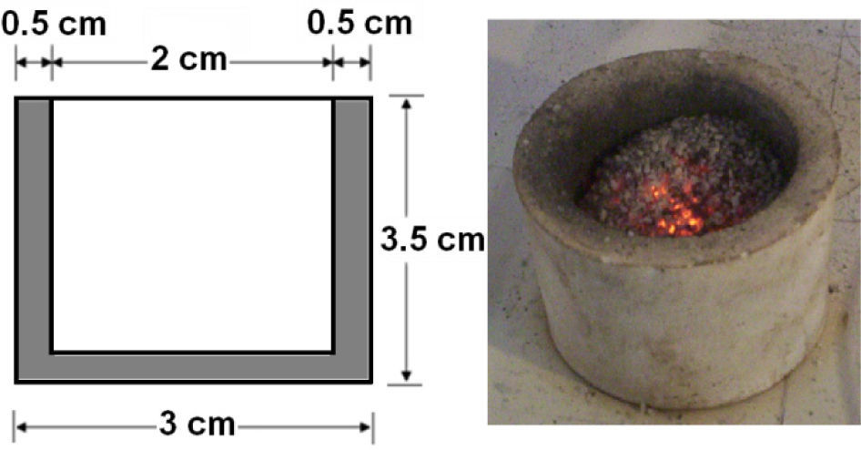
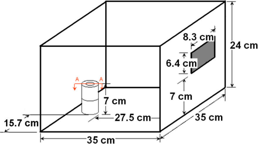
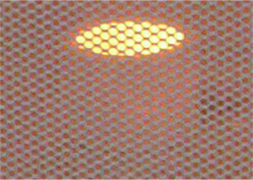
The most suitable location for placing the sample in the cavity was determined by tests with an alumina crucible filled with graphite (figure 1) and located in different places over the floor of the cavity. One of the places were graphite showed incandescence, about 500°C, in less than 5 seconds was taken for conducting the expansion tests. It was decided after additional experiments considering height over the floor that the best option was placing two crucibles, one above the other with the sample inside in the crucible on the top (figure 2).
 and a picture of one of them after the test.")

Thermal evolution of the sample was followed with an optical pyrometer of narrow angle pointing to the surface of the sample in the crucible. Temperature measurement is always an issue in microwave processing; first step was finding a good location for the pyrometer, aiming it through different holes over the cavity that are used for ventilation and that are accessible after removing the external cover of the oven. The holes in the shield of the door were also considered following previous reports 17.
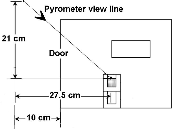
It is expected under the hypothesis of microwave volumetric heating that the surface of the sample is cooler than the inner part due to the heat losses, while possible graphite combustion could increase the temperature of the same surface covered by the optical pyrometer. For having and idea of the reliability of the temperature measurements, a thermocouple was quickly inserted at the end, right after microwave power was shut off, of some tests conducted for this purpose. Measured temperature in the sample was higher, but the maximum difference was less than 50°C, then it was considered that measurements were reliable since they are in the accuracy order of this technique were other sources of error, such as hot spots in the sample and the door interference, are present. After all of these considerations the pyrometer was fixed in front of the oven aiming to the sample through the door, as the scheme of figure 3 shows.
2.3Perlite / graphite ratio")
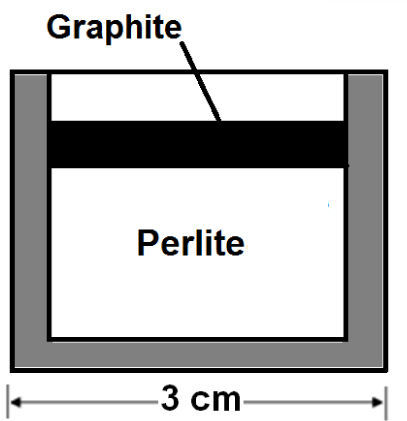
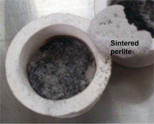
The appropriate amount of graphite was estimated following a method used in a previous research with MgO and Al2O318. A sample of 10g of perlite PC-24+30 without graphite, as reference, exposed to microwaves for 5 minutes reached only 200°C, which indicates that perlite has certain absorbance because empty crucibles did not reach more than 60°C in the same time. Another test consisted in heating 9g of perlite covered with 1g of graphite (figure 4); it heated to 800°C in about a minute. In this second tests the particles were collected by digging from the surface of the sample; 57% of the particles in the first layer under the graphite, doubled their size, but less than 0.2cm below this layer the perlite was not expanded.

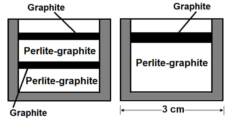
After confirming the effectiveness of the graphite as susceptor of microwaves, it is necessary to find the optimal arrangement in terms of perlite expansion. Three arrangements with 2g of graphite and 8g of perlite were tried: (1) perlite in the crucible covered with graphite (as in figure 4), (2) two alternated layers of graphite and mixture of perlite-graphite, and (3) mixture of perlite-graphite covered with a layer of 0.5g of graphite (figure 5). The total mass of graphite is the same for the three arrangements; all of them were exposed to microwaves for 60 seconds and the sample in the oven looks like in figure 6.
. Mixture of perlite-graphite covered with a layer of graphite (right)")

Two extremes were found in the samples from arrangement (1); sintering close to the graphite layer, and no expansion and no change far from that layer. In the second arrangement (2), perlite was sintered (figure 7), and in the case (3), practically all the sample presented expansion with few sintered particles; most of them far from the graphite.

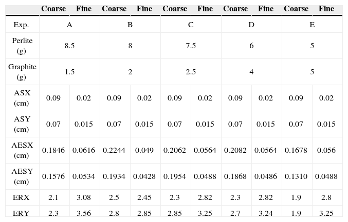
According to the results of these preliminary tests, the third arrangement was used and the experimental set of Table 2 was designed. The experimental time of 120s ensured that the entire sample was heated up, but when the sample reached 870°C, the test was terminated, even if 120 seconds had not elapsed.
Results of the tests for expanding coarse perlite (CP-24+30) and fine perlite (CP-40)
| Coarse | Fine | Coarse | Fine | Coarse | Fine | Coarse | Fine | Coarse | Fine | |
|---|---|---|---|---|---|---|---|---|---|---|
| Exp. | A | B | C | D | E | |||||
| Perlite (g) | 8.5 | 8 | 7.5 | 6 | 5 | |||||
| Graphite (g) | 1.5 | 2 | 2.5 | 4 | 5 | |||||
| ASX (cm) | 0.09 | 0.02 | 0.09 | 0.02 | 0.09 | 0.02 | 0.09 | 0.02 | 0.09 | 0.02 |
| ASY (cm) | 0.07 | 0.015 | 0.07 | 0.015 | 0.07 | 0.015 | 0.07 | 0.015 | 0.07 | 0.015 |
| AESX (cm) | 0.1846 | 0.0616 | 0.2244 | 0.049 | 0.2062 | 0.0564 | 0.2082 | 0.0564 | 0.1678 | 0.056 |
| AESY (cm) | 0.1576 | 0.0534 | 0.1934 | 0.0428 | 0.1954 | 0.0488 | 0.1868 | 0.0486 | 0.1310 | 0.0488 |
| ERX | 2.1 | 3.08 | 2.5 | 2.45 | 2.3 | 2.82 | 2.3 | 2.82 | 1.9 | 2.8 |
| ERY | 2.3 | 3.56 | 2.8 | 2.85 | 2.85 | 3.25 | 2.7 | 3.24 | 1.9 | 3.25 |
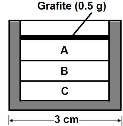
After the microwave processing the particles were recovered from three zones in the crucible (figure 8). It was found that the material in the top zone (zone A), which was in contact with the graphite layer, was sintered, while perlite in zones B and C are expanded, although zone B also presents particles incipiently sintered. Loosen particles from zone B were taken for the expansion measurement.

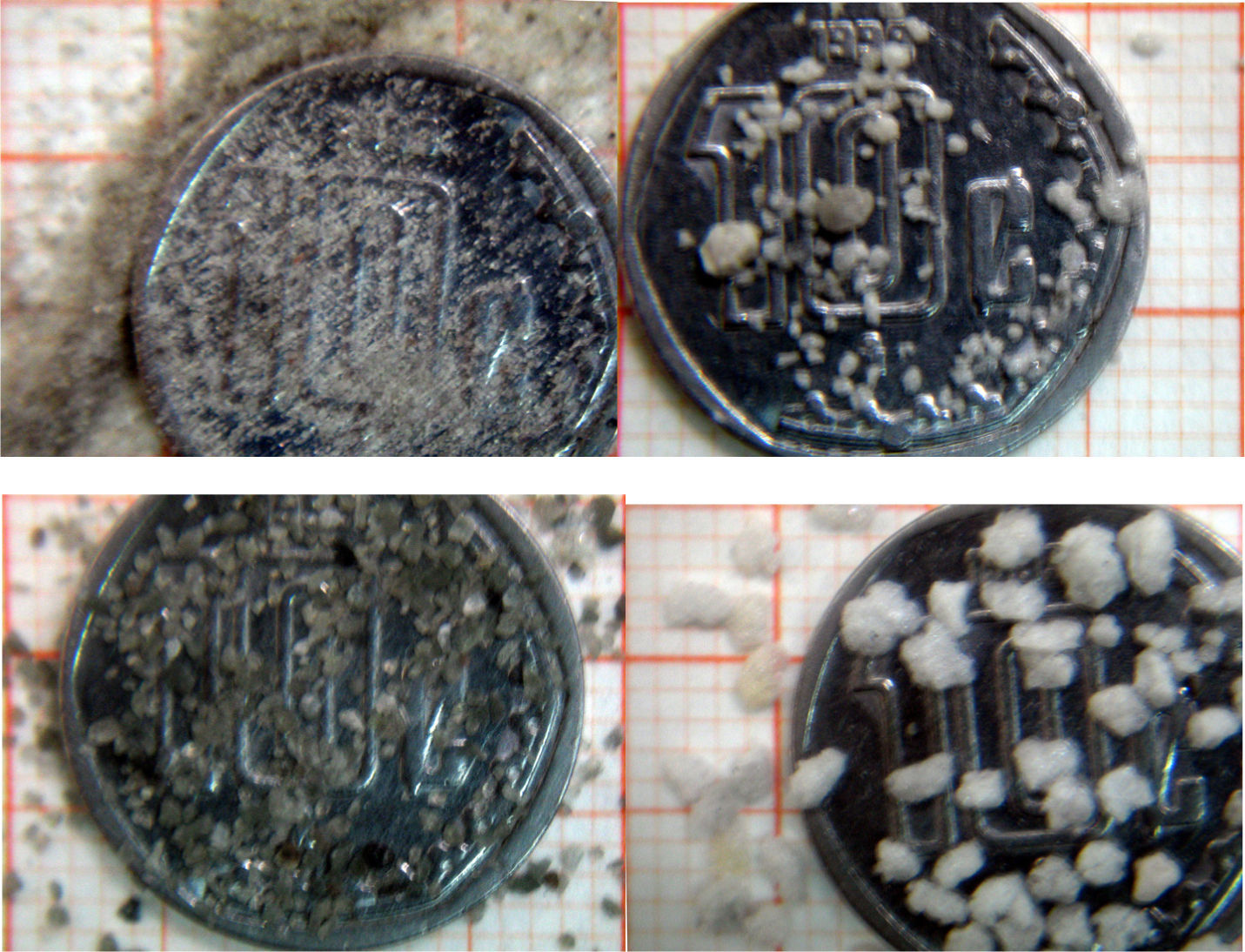
Figure 9 shows a comparison of the particles CP-40 and CP-40+30 before and after expansion. It can be seen that in general they preserve their original shape. Measurements from each experiment, showing the expansion ratios, are summarized in Table 2.
 and CP-40+30 (below). The grid is 1mm2")
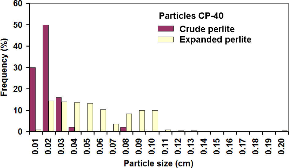
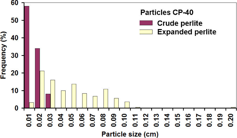
Histograms of expanded CP-40 are shown in figures 10 and 11; it can be noticed that most of the particles grew linearly between 2 and 3 times along axes X and Y.


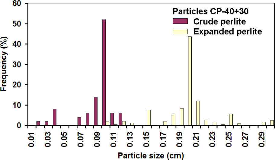
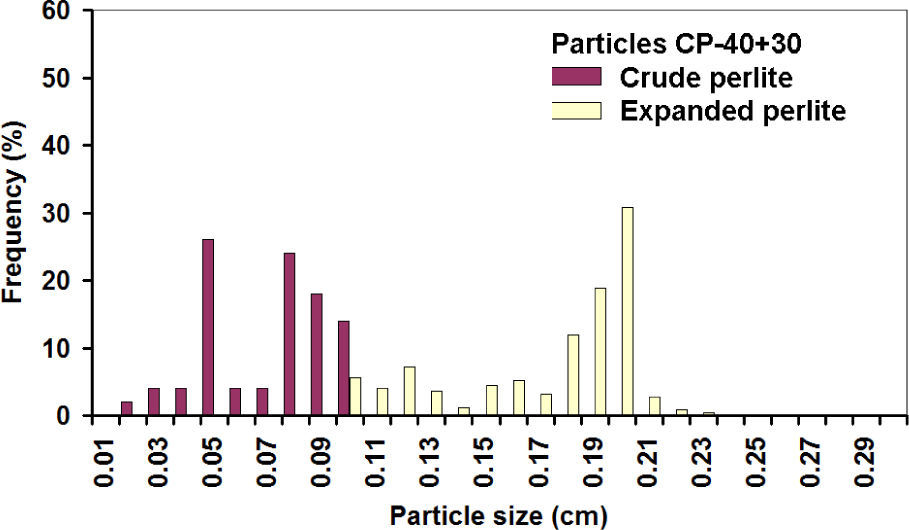
It is assumed that the same happened with the third axis, and then the linear increase of 2.15 times corresponds to a volumetric expansion of 10 times, while a 2.71 value corresponds to the theoretical values of 20 times. Similar expansion grades were obtained in the PC-24+30 (figures 12 and 13). In this case, the populations before and after the expansion are well-defined, showing that indeed expansion occurred in all the particles, achieving about the same theoretical expansion.


The overlap of the crude particle distribution and expanded perlite for the fine particles is explained because for the CP-40; only particles smaller than mesh 40 are considered, thus very fine particles were counted in the first class interval. The first class interval in the distribution of crude coarse particles is not overload since CP-24+30 sizes are limited between meshes 24 and 30.
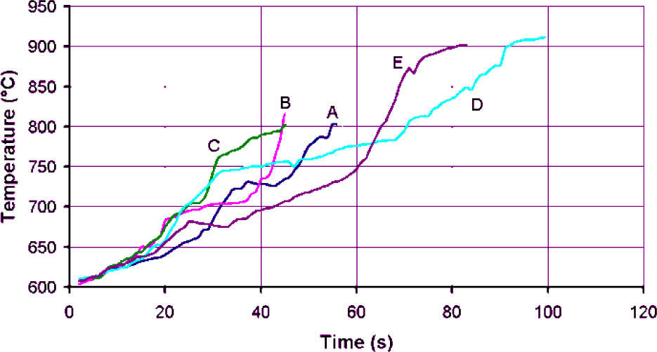
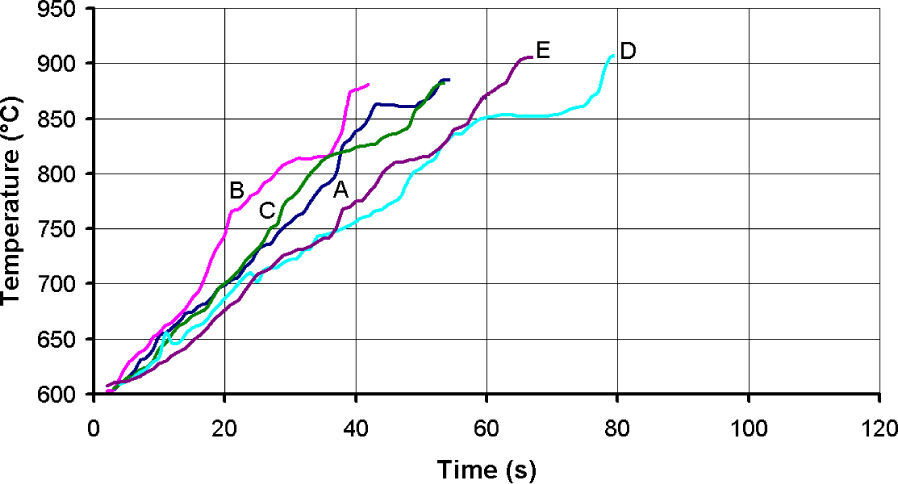
Thermal evolution of the test of particles CP-40 and CP-24+30 are shown in figures 14 and 15 respectively. The heating slopes show that fine materials absorbed less microwave energy than larger ones; the idea was to stop the test when temperature reached 870°C, but that was not always possible. In the case of CP-40 particles, during the tests A, B and C a flame was formed over the crucible that forced to terminate those tests ahead of time.


Despite the efforts of covering the sample with more graphite or perlite, it was not possible to avoid the flame. The plots are cut at the maximum achieved temperature, which happens to be around 870°C. However, an interesting observation here is that in tests A, B and C of fine particles the maximum achieved temperature is in the order of 800°C, and the obtained expansion is in the same order than that achieved in the rest of the tests taken to 870°C. Something that must be explained is the rapid increased to 600°C, which is the minimum temperature that the optical pyrometer is able to take, and how the heating slope in figure 14, was reduced from about 200°C/s to 2.5°C/s, while in figure 15 the respective heating slope changes to about 5°C/s. The explanation is that at first, few particles of graphite that heat up quickly to that temperature are detected by the pyrometer, but average temperature is not that high, and as more material gets hotter, the system reads a volumetric temperature more uniformly. It was confirmed that the samples that took longer to reach 870°C, which is the supposed beginning of the expansion, are the most sintered because they stayed longer at sintering temperature. The overheating after stopping the test at 870°C is an evidence of non uniform temperature and that the inner of the sample is hotter and heat is transferred to the surface were the pyrometer is measuring the temperature. The temperature gets uniform after the test is finished and that is the reason why the thermocouples inserted at the end of the tests have a good coincidence with the optical pyrometer readers. It can be also noticed that samples with less graphite heated up at higher rate, one probable explanation is that graphite becomes less absorbent at high temperatures, and if the amount of graphite, which is of low density, is larger such as in tests D and E, graphite volumetrically was taking the control of the heating process. In the case of the experiments with less graphite, it is expected that perlite increases its capacity for absorbing microwaves at high temperature as alumina and spinels do, and although that was not confirmed in this work, it is possible to speculate that in those cases perlite takes the control of the heating process.
Since the optical pyrometer was fixed in a location for all the tests, the thermal profiles comparison is valid for determining that the maximum heating slope was obtained with 2.5g of graphite and 7.5g of fine, and 2g of graphite with 8g of coarse perlite, suggesting that there is an optimal amount of graphite to be employed. Graphite did not get in combustion for any of the tests of coarse perlite. Regardless the heating slopes and the achieved temperatures, the expansion was about the same in all of the cases, since temperature exceeded 800°C the sintered zone was larger in those cases were temperature was higher and sustained by longer time, as in tests E and D, which are richer in graphite, reducing the amount of expanded free particles. Given that this effect is more noticeable in all of the cases with more graphite, at the same time than in this condition the sintered zone is larger, and indeed less sample is being heated, it is advisable to reduce the amount of graphite, even if tests are reduced in time because of combustion.
4ConclusionA method for expanding perlite by means of microwaves was presented and demonstrated that linear expansion is between 2 and 3 times, which volumetrically implies that even theoretical, 20 times expansion, is feasible.
Given that in all of the cases the expansion of perlite was obtained regardless that the tests were stopped or the perlite / graphite ratio employed, it can be assumed that the expansion of perlite is possible at suggested temperature of 870°C.
Graphite was a suitable substance to act as a thermal susceptor, in large amounts is less efficient in this function. Since only loosen particles in the sample were taken for measurement, in the tests with more graphite which lasted longer, the sintered zone was also larger and fewer particles were recovered. It is important to minimize the amount of graphite for maximizing the amount of free particles.
Authors express their gratitude to Alejandra Soni García for her help during her Summer Stay of Science (PROVERICYT); Consejo Nacional de Ciencia y Tecnología (CONACYT) / Programa de Apoyo a la Ciencia y Tecnología (PAICYT-UANL). Zarel Valdez is currently a researcher of the Centre National de la Recherche Scientifique at the Laboratoire Plasma et Conversion d'Energie (LAPLACE laboratory) in the University of Toulouse, France.