


The nonlinear feedback cascade model of the underactuated IWP is obtained through a collocated partial feedback linearization and a global change of coordinates. A nonlinear controller is designed with the nonlinear recursive technology. The system stability is proved with Lyapunov theory. The simulation results show the system is globally asymptotically stable to the origin.
Many researchers focus on the inertia wheel pendulum (IWP) to look it as a test bed for the effectiveness of control algorithms [1-5]. There are two control problems in this system: one is to control the pendulum swinging up from the hanging position to the upright vertical position; the other is to stabilize the IWP around its unstable equilibrium point. Much remarkable work is done: a control energy approach based on the passivity [1] is used to solve the balance problem of the IWP. The interconnection and damping assignment passivity based control [2] is used for the asymptotic stabilization of the IWP around its top position while two necessary matching conditions have to be satisfied in order to obtain a stabilizing controller. A nested saturation function [3] is used to stabilize the IWP. To reduce the dependence upon the Lyapunov functions, a backstepping approach [4] is proposed and a complex controller is obtained. A recursive design algorithm is designed for the inertia wheel pendulum, but a sigmoid function is needed [5].
In this paper the asymptotic stabilization is considered for the underactuated and strongly damping IWP around its unstable top position. Our main contribution is to utilize a suitable set of transformations that allows us to accomplish a nonlinear control design with the recursive technology to bring the system to the unstable top position. This paper is organized as follows. In Section 2 we present the IWP model and the model transformation to obtain the strict feedback cascade model. In Section 3 we develop the control strategy based on the recursive technology. In Section 4 some simulation results are given and Section 5 is the conclusions.
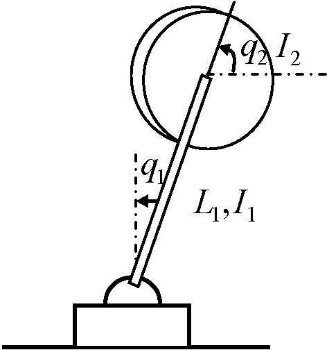
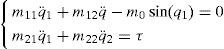
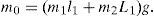
2The IWP system modelThe inertia wheel pendulum is shown in Figure 1, which consists of a physical pendulum with the equivalent mass m1 and a revolving wheel with the equivalent mass m2 at the end. The motor torque produces an angular acceleration of the revolving wheel which generates a coupling torque at the pendulum. The task is to stabilize the pendulum in its upright equilibrium point while the wheel stops rotating. The specific angle of the rotation of the wheel is not important. The revolving wheel is actuated and the joint of the pendulum at the base is unactuated. That is to say, it is a benchmark example of the underactuated mechanical system [6, 7], which has one control input τ and two configuration variables (ql, q2), and its Euler-Lagrange equations of motion can be obtained as


In order to simplify the system dynamics. The following collocated partial feedback linearization [8] is used
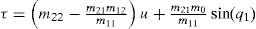
The dynamics of the shape variable q2 is simplified to

The following global change of coordinates [9] is designed
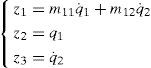
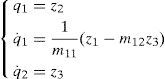
to transform the system dynamics into a nonlinear system as
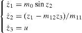
Since that q2 does not play any important role in the dynamics of the IWP, it is ignored as a state variable. From Eq. 4, it can be seen that the system model of IWP is a nonlinear feedback cascade model.
3The nonlinear controller design through recursive technologySince the model of IWP can be transformed into a cascade nonlinear system with a collocated partial feedback linearization Eq. 2 and a global change of coordinates Eq. 3, the controller can be designed with the recursive technology. The design process is:
Step 1.From the dynamic equation of state xl in the IWP system model Eq. 4

Firstly look z2 as the virtual control input and define a reference trajectory z2r for z2 to follow as

which leads to an error e2 defined as
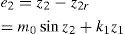
where, k1 is a positive constant.
Consider a scalar positive definite Lyapunov function given by
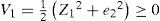
The time derivative V˙1 is given by
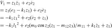
We note that the variable z3 enters the right hand side of Eq. 7. We now proceed to look z3 as the control variable and design a reference trajectory z3r for it to make the second term of right hand in Eq. 7 be non-positive.
Step 2.In step 1, the time derivative of the Lyapunov function V1 is obtained in Eq. 7. In order to make the V˙1 be a negative definite function, state z3 is looked as the virtual control input in Eq. 7. A reference trajectory z3r is defined as

The tracking error e3 defined as
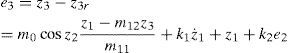
So
We modify the scalar positive Lyapunov function V1 ≥ 0 as
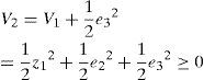
Differentiating V2
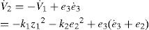
From Eq. 8,

The system control variable u = ż3 enters in the right hand of the Eq. 11.
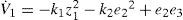
Step 3.In order to make the V˙1 be a negative definite function, we can make the following equation hold since the control variable arises.
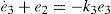
Such that
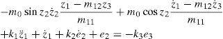
Therefore, the control law can be obtained from Eq. 13 as
Theorem 1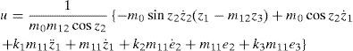
The feedback cascade model Eq. 4, which is transformed from the IWP system described by Eq. 1 through the collocated partial feedback linearization Eq. 2 and the global change of coordinates Eq. 3, is asymptotically stable under the control input Eq. 14.
Proof:The recursive design process has proved: the time derivative of the chosen positive definite Lyapunov function V2 is negative definite. That is to say, the three terms of the right hand in Eq. 9 is asymptotically approach to 0. Since that the first term z12/2 approaches to 0, z1 must asymptotically approach to 0. From the second term e22/2 approaches to 0, e2 must asymptotically approach to 0 and it is known from Eq. 6 that z2 must asymptotically approach to 0. The third term e32/2 approaches to 0 implies that z3 asymptotically approach to 0 from Eq. 8.Therefore, the system states (z1,z2,z3) of the IWP described by Eq. 4 asymptotically approach to (0,0,0).
Remark 1Both the collocated partial feedback linearization Eq. 2 and the global change of coordinates Eq. 3 in the second section are invertible transformation, which is
It can be seen from Eq. 15 that (z1,z2,z3) asymptotically approach to (0,0,0) implies that (q1,q˙1,q˙2) approach to (0,0,0,0). The control input τ can be calculated with Eqs. 2, 14 and 15.
Remark 2There is a singularity when z2 = ±π/2 in the controller Eq. 14. The method to deal with the singularity in the simulations is: the cosz2 in Eq. 14 is represented by a positive number (φ) for z2 ∈ (π/2−Δ, π/2) or Z2 ∈ (−π/2, −π/2+Δ), and by a negative number (−φ) for z2 ∈ (π/2, π/2+Δ) or z2 ∈ (−π/2−Δ,−π/2). The value of φ can be decided by the output limit of the actual controller.
Remark 3The design method is proposed for the nonlinear feedback cascade system Eq. 4, so it can be used for all the underactuated mechanical systems that can be transformed to the cascade system Eq. 4, such as the TORA and the Acrobot. Compared with other recursive controllers, the proposed algorithm is simple and easy to be implemented as the implementation of the neural control systems [10].
4Simulation studiesIn order to test the proposed control algorithm, the following system parameters [11] are used:
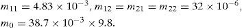
The parameters of the nonlinear controller are chosen as

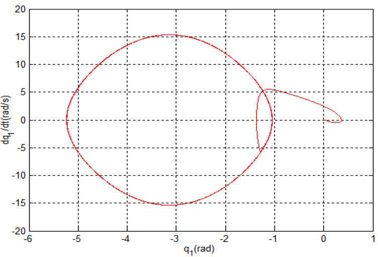
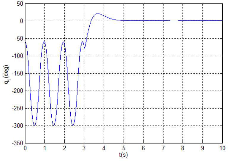
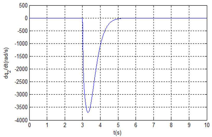
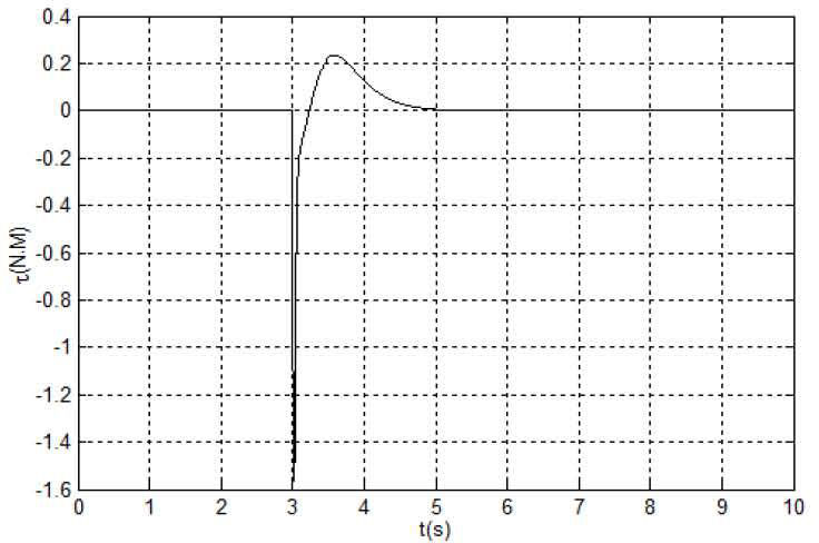
The simulation results are shown in Figures 2-5.


The simulation results in Figures 2-5 are obtained under the initial state (zl, z2, z3) = (0, −60°,0) i.e. (q1,q˙1,q2) and the proposed control algorithm is added at 3rd second. Figure 2 is the phase plane of the (q1,q˙1), Figure 3 is the time response of ql, Figure 4 is the time response of q˙2 and Figure 5 is the control torque τ of the IWP. It can be seen from the simulation results that: the IWP system is freely swinging before the control algorithm is added and the IWP system is asymptotically stable under any initial states with the proposed control algorithm. On the other hand, the control performance can be improved through adjusting the parameters of the proposed controller. Lots of simulation experiments show that the parameters k2, k3 respectively correspond to the system state q1,q˙1, therefore it is easy to adjust the parameters for an improved system performance.
5ConclusionsA collocated partial feedback linearization and a global change of coordinates are used to transform the underactuated IWP to a nonlinear feedback cascade system. A nonlinear control algorithm is proposed with the recursive technology. A Lyapunov function is found step by step in the design procedure and illustrates the system stability. The design method is proposed for the nonlinear feedback cascade system, so it can be used for all the underactuated mechanical system that can be transformed to the cascade system.
This work is supported by a Project of Shandong Province Higher Educational Science and Technology Program (No.J13LN25) and the National Natural Science Foundation of China (61175086).