


Cactus prickly pear (Tuna) harvest is a complicated operation that continues in a rudimentary way, in the majority of cases manual and with the help of tools such as knives and rods which sometimes affect the fruit. In this research is analyzing the possibility of building a tool that meets the characteristics sufficient for a good harvest, one of the factors to consider is access due to the restrictive features of the cactus prickly pear (height and distribution of the joints), forcing the use of tools to achieve it (with sometimes unfavorable results). This is how arises the need to create a device that adapts to the needs and solve the problem of harvest of tuna. Field studies which were fundamental to the design, such studies were obtained measurements and tests of strength, which were carried out with instruments properly designed for the type of fruit. Generated a picker mechanism of cactus prickly pear (tunas), which according to your design could achieve a high level of harvest compared to which today has, thanks to the configuration of the mechanism and the way they get their movements lead to a suitable environment for personnel performing this activity.
Cactus prickly pear (Tuna) is an operation that is performed manually and with the support of rudimentary as knives and rods tools even with the passage of time. This activity consists of two steps, the first is to reach the fruit and the second release it, the first step is usually attended by pole when the fruit is high, while that for the second the fruit with one hand and held a small cut to the stalk or a twist to the tuna of approximately 90° producing a torque, leaving the fruit detached. Analyze the possibility of building a tool that meets the characteristics sufficient for a good harvest and improve the working environment; it refers necessarily to investigate (Durán-García, Romero-Méndez, Delgado, García, & Delgado, 2013).
Having volumes of harvest at the industry level and low cost, is a determining factor to carry out studies on the mechanization of the harvesting process (Ortiz-Laurel & Rössel-Kipping, 2011). The harvest of tuna and especially of the type Alfajayucan, is dangerous and difficult especially when you are looking for in more quantities, because there are factors that make it difficult to achieve the desired goals; one of these factors is the access due to the restrictive features of the cactus prickly pear (height and distribution of the tuna), forcing the use of tools to achieve it (Rossel, Ortiz-Laurel, & García, 2004). As is necessary to create a device that adapts to the needs and solve the problem of tuna harvest complying features such as: (1) remove the fruit without causing damage, (2) reaches the fruit more remote, (3) improve the working environment, (4) be operated under any environmental condition, (5) harvest level is greater than the one done manually and (6) easy to use for the operator.
A series of studies carried out in the orchards of the community of Victoria, municipality of Pinos, Zacatecas (Mexico); we collected data of importance for the sizing of the arm. Data, it was estimated that the production level is approximately 6.500tons, harvested entirely by hand; the daily collection is equivalent to 240kg of tuna Alfajayucan; It therefore seeks to arm more than the harvested manually. To comply with the proposed alternatives were analyzed to separate the fruit from the stalk, as well as hold subject while it is transported to the storage bin. In the development were taken into account existing devices for harvesting of tuna and other fruits (Durán-García et al., 2013; Mueller, Shoop, & Laycock, 1994; Ortiz-Laurel & Rössel-Kipping, 2011), in addition to physical restrictions such as length and diameter of the tuna, wide, thickness and weight of the joint (NMX-FF-030-SCFI-2006).
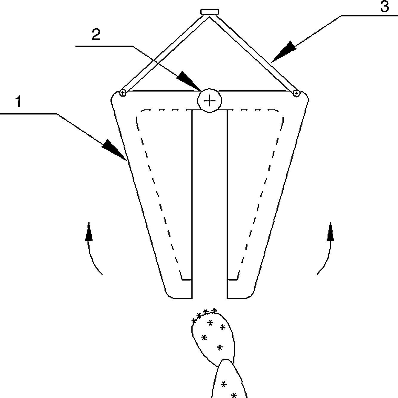
Known restrictions generated alternative to conceptualize the device of cutting and clamping, resulting in the alternative shown in Figure 1, which works in the following way: the brackets (item 3) are elevated by means of a hydraulic piston, overcoming the action of a spring; this movement allows the blades of collects (point 1) open the angle necessary to gain access to the fruit, the blades are subject to a fixed point from which is made the rotation (point 2). At the moment of device in the desired stops applying pressure to the actuator and the spring shovel return to its original position, setting the fruit, once harvested the tuna, this is fixed in the tank and the actuator is operated to release the fruits.

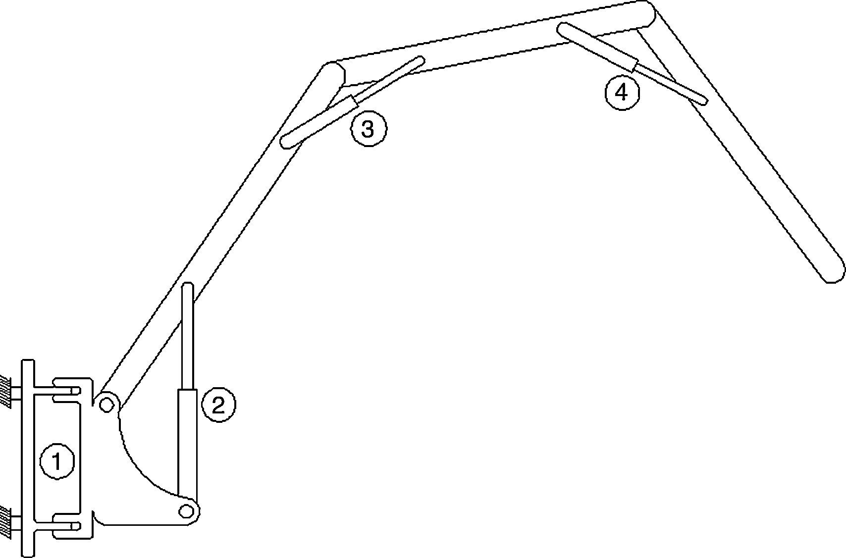
To position the cutting tool and prevent damage to personnel, a mechanism of 4° of freedom are studied and proposed the use of a tractor to provide support and power to the arm for mechanical harvesting of tuna (Figure 2).

The arm corresponds to a mechanism of open chain of four degrees of freedom, in which each link operation is carried out by means of hydraulic Pistons. The link 1 will have an angle of action of 160°; the remaining three will have a range of 80°. The parameter considered in the choice of positioning mechanism was the maneuverability, as it is reflected in the desired volume of harvest.
2Development2.1Structural calculationThe reactions in each one of the elements of the machine are determined in this section.
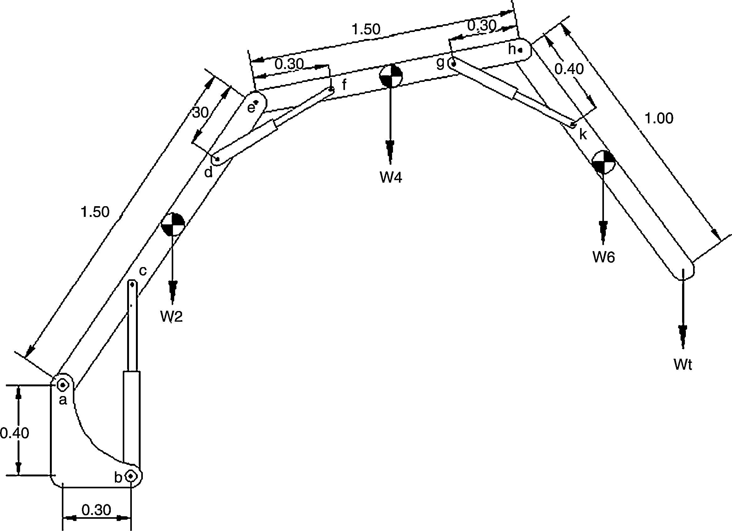
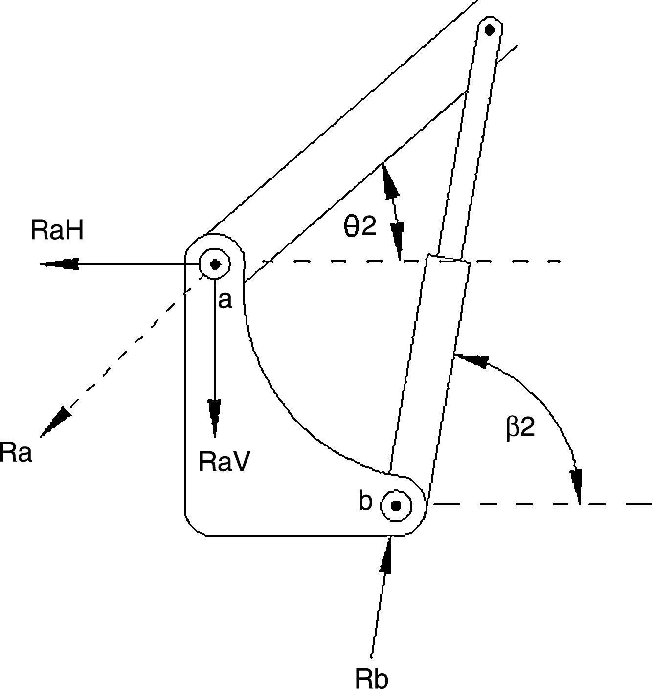
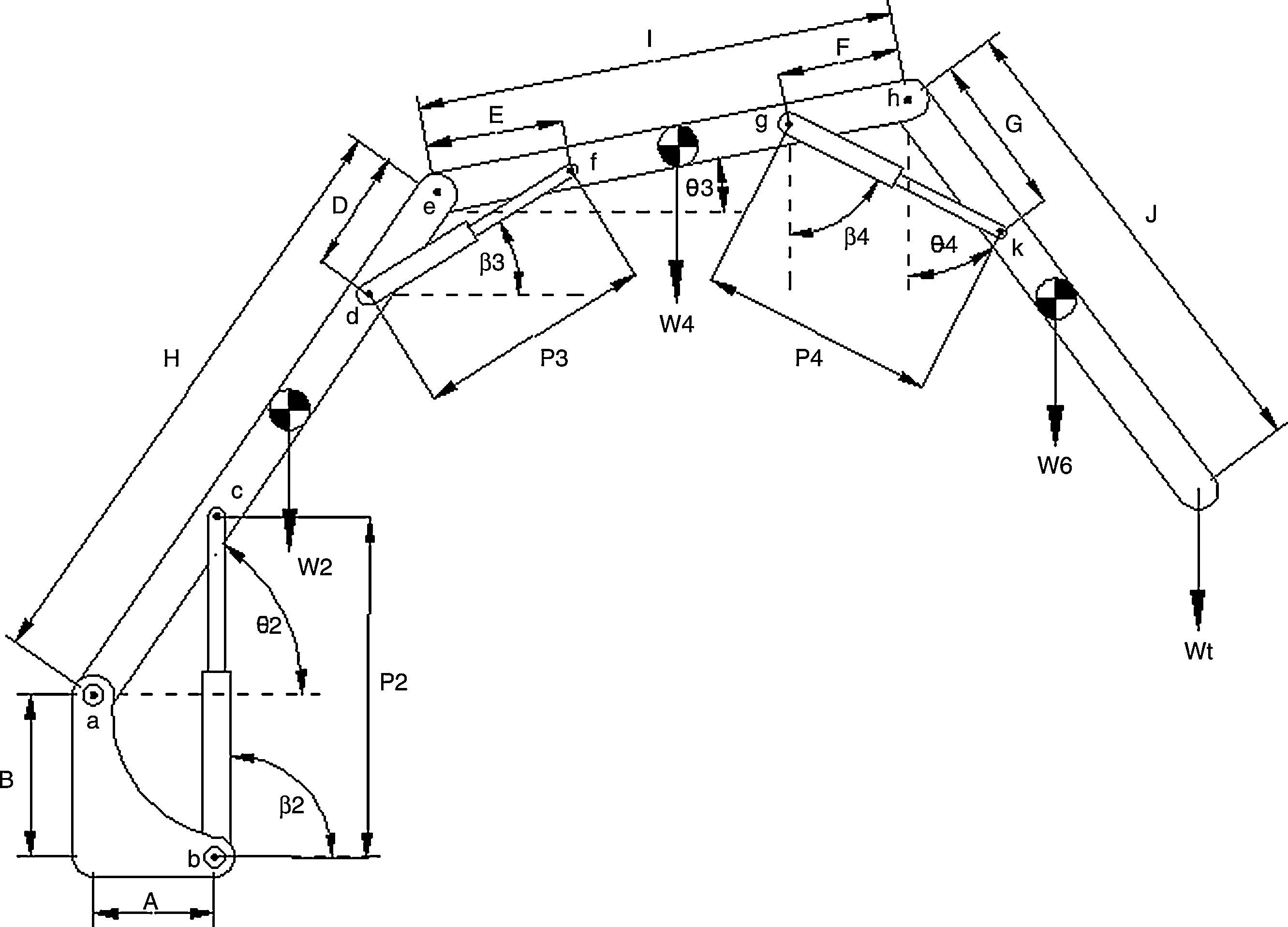
The W2, W4 and W6 loads correspond to the weight of each item; W1, W3 and W5 is the weight of the hydraulic actuators, Wt corresponds to the force exerted by the load to be lifted (Figure 3). The first step in the structural calculation is to determine the external reactions, such reactions are calculated taking into account the burden of all the frame and considering that at points “a” and “b” (union of the mechanisms of movement, vertical and horizontal, Figure 4) are given the reactions of the total load.


To determine the value of the reactions is sum of moments from point “a” (Figure 5, Eq. (1)).
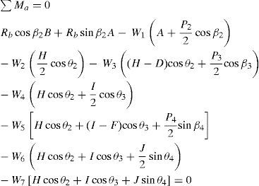

Known Rb reaction is to determine the value of the components of the reaction at “a”. Subsequently, the frame is disassembled and reactions and the led bar of the mechanisms 2, 3 and 4, with dimensions H, I and J are determined; analysis begins in the mechanism 4.
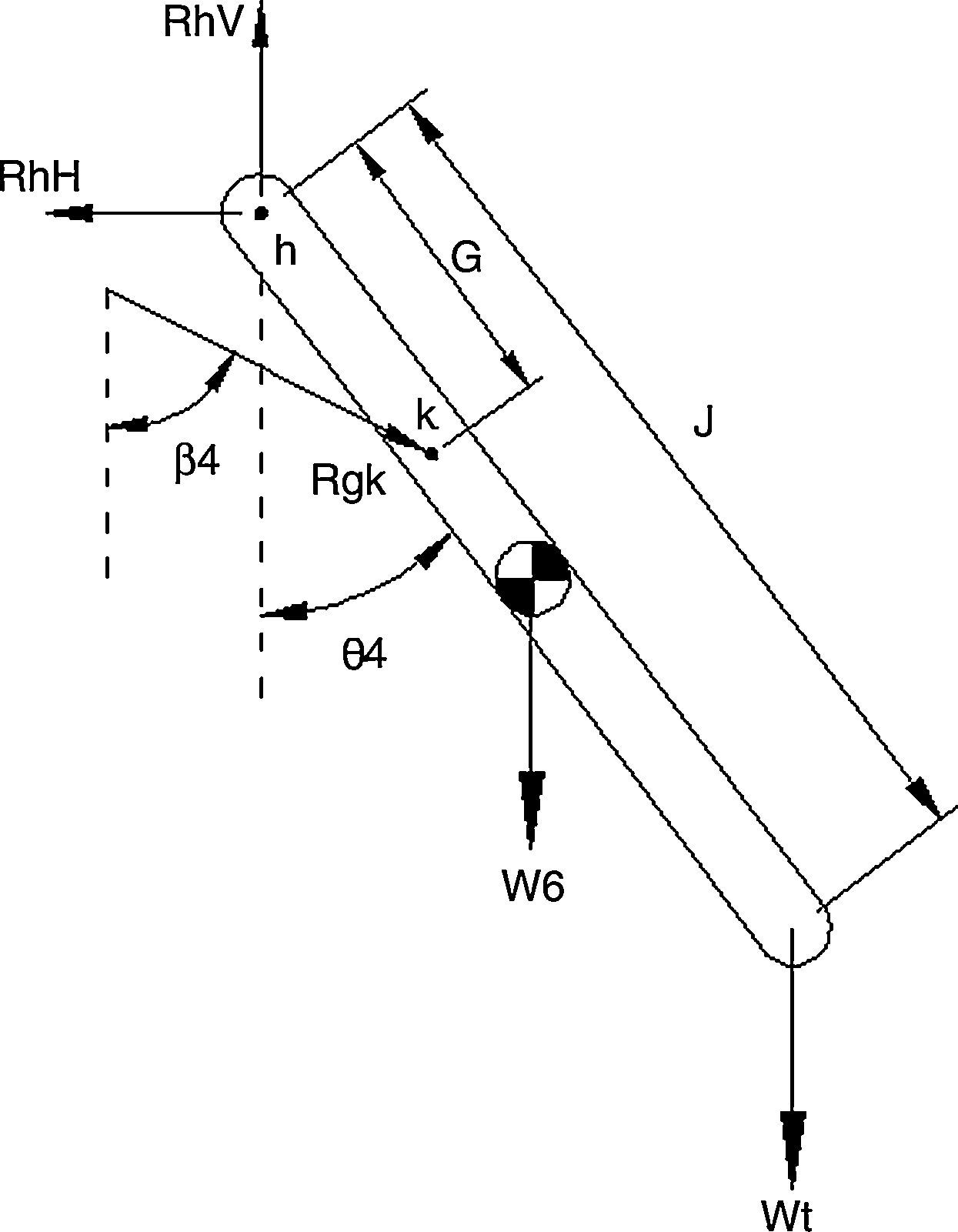
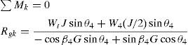
2.2Structural calculation of the link led on the mechanism 4Figure 6 shows the diagram of forces acting on the led bar. Reactions are produced directly by the load to lift, varying in relation to the working angle. Each of the elements is subject on a node, that the components are equal and opposite on each of the elements. To know the reactions RhV, RhH and Rgk involved in the mechanism is sum of moments in the “h” point, giving form to Eq. (2) in which the only unknown variable is Rgk.

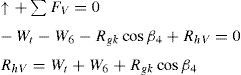
The rest of the variables is through the sum of vertical and horizontal forces, obtaining values of RhV and RhH (Eqs. (3) and (4)).
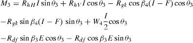
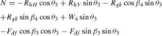
Found the value of reactions remains to know the efforts, for this determines the resulting (Gere, 2003) which is in the form of bending moment (M) and (N) axial forces along the beam (Eq. (5)).
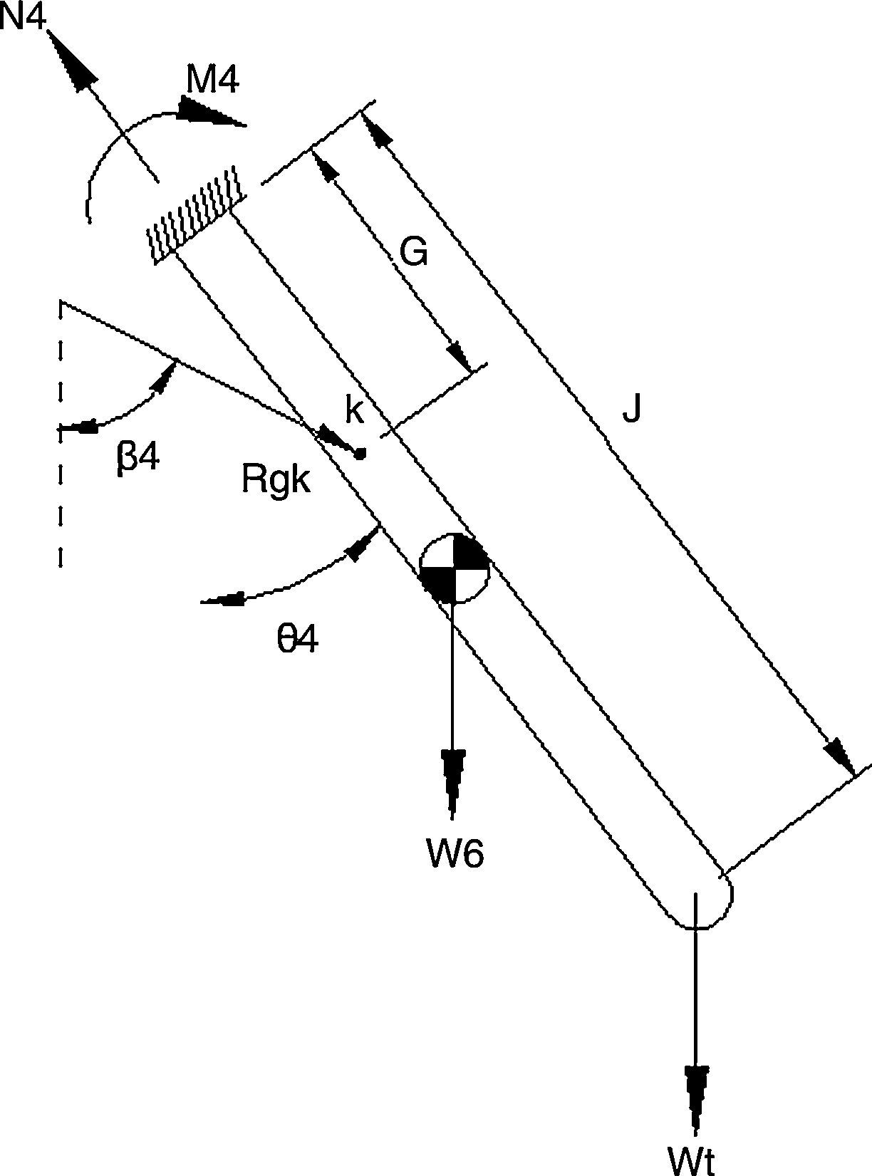
where A is the area of the cross section and I the moment of inertia of the cross section with respect to the neutral axis, as well for the effort on this element is calculated the bending moment (Eq. (6)), which is obtained by summation of moments at the point h (Figure 7).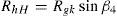
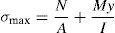
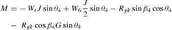

Figure 7 shows moments and axial forces in four mechanism led bar.
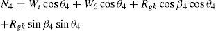
Obtained the value of the bending moment, is the total axial force (Eq. (7)) which acts on the element.
The maximum effort to tension and compression are obtained with the bending moment, axial force and the geometry of the element (0.14 by 0.10m). The value of these efforts was numerically determined by MATLAB, the maximum effort to tension and compression is 7.73MPa and minimum of 17.7kPa (Pa=N/m2).
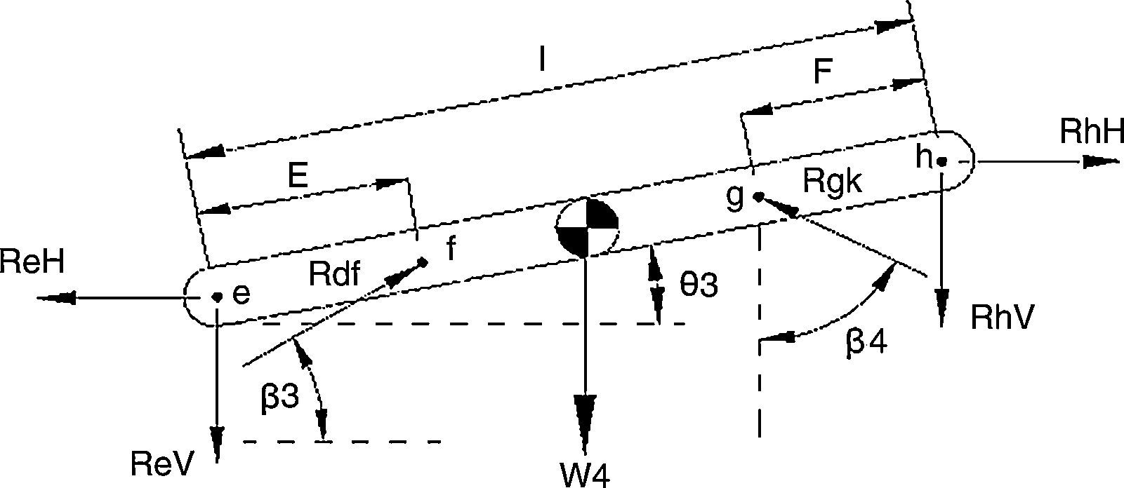
2.3Structural calculation of the link led on the mechanism 3Known h reactions it is possible to consider the solution of the three mechanisms, each of the elements is subject on a node, that the components are equal and opposite on each of the points, subtract to know the reactions at the opposite end of the element (point e, Figure 11).
To know the reactions ReV, ReH and Rdf, is sum of moments from the point e, giving form to Eq. (7) in which the only unknown variable is Rdf (Figure 8).

For the effort on this element is calculated (moment Eq. (8)), doing sum of moments from the point e (Figure 8).
Determined the value of the bending moment, is the axial force acting in this element (Eq. (9)).
With the bending moment, axial force and geometric characteristics (0.16 by 0.10m), gets the maximum effort to tension and compression. The value of these efforts is numerically using MATLAB resulting in a maximum effort to tension and compression of 17.4MPa and a minimum of effort of 0.57MPa
2.3.1Structural calculation of the link led on the mechanism 2The two mechanism led bar is which supports mechanisms three, four and five (Figure 9).

The reactions present in this element are all known as share points of union with elements of the arm which were previously analyzed. These include union according to Figure 3 are: a, e and c known the value of reactions, subtracts know of efforts (Figure 9).
The effort on this element is determined by calculating the bending moment, which is obtained by summation of moments from the point to Eq. (10) and Figure 9.
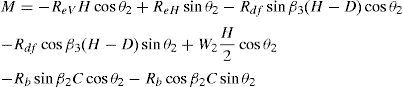
We have obtained the value of the bending moment; the total axial force is located.
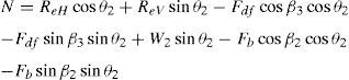
The bending moment and axial force and the geometrical characteristics of the element (0.20 by 0.10m) gets the maximum effort to tension and compression. The value of these efforts is numerically via MATLAB resulting in the maximum effort to tension and compression of 25.5MPa and 2.54MPa.
Determined efforts, it is possible to select the material to be used for the construction of the elements (opted for aluminum) which according to Gere (2003) has a maximum value of effort to creep between 41 and 152MPa.
2.4Force on the piston2.4.1The mechanism of harvest pistonIt is a single acting piston that drives the shovels they bear fruit, mechanism in initial or rest state meets both shovels closed due to the action of the spring, to gain access to the fruit actuates the piston which overcomes the spring (opening such shovels), when you have positioned the fruit is left to operate the piston and the mechanism returns to its initial position.
On the mechanism of harvest (Figure 10), vectors represent the position of each of the masses, these are derived to determine the vector speed of each mass and once again to know the acceleration vector:


Known the magnitude of the vectors, the free body diagram, is as follows:
The numeric value of these unknowns was obtained by means of a code in MATLAB.
Force minimum in the piston 17.000907N.
Force maximum in the piston 21.013257N.
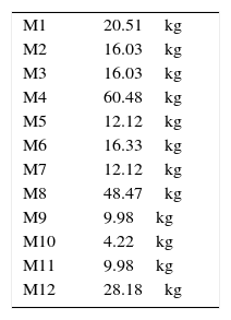
Position mechanism is formed by three actuators, and each one gives movement to an independent mechanism. The mass of each component of the machine consists of concentrated masses and this serves to calculate the force on each of the actuators. The value of each mass is obtained according to Eqs. (13)–(15).


Eq. (13) assures that the value of concentrated masses is equal to the value of the mass of the corresponding element, Eq. (14) assures that the time by each of the masses is the same regardless of the proposed length, finally Eq. (15) equal moment of inertia of the studied the sum of times element generated by concentrated masses. To find the value of such masses were resolved constraint equations by substitution, leaving in the following manner:
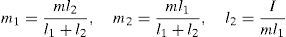
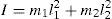
Solved the constraint equations, the next step to find the equivalence of the masses is to propose the length l1, and thus find the length l2 depending on the moment of inertia and the mass of the element; the value of the two concentrated masses is defined by the length values. These equations were solved numerically by the following data:
The distribution of the masses found lengths shown in Figure 11.

With concentrated masses known vectors of position, velocity, and acceleration of each, with respect to a fixed system and the vector of each of concentrated masses is divided into components corresponding to each axis. The vectors of the mass 1 and 2 do not imply a force on the mechanism's position since they are not based on the actuators; therefore do not have speed or acceleration.
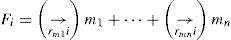
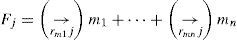
The calculation of the strength of each mechanism implies the multiplication of each of the masses by its corresponding acceleration for the force needed to make a move to a desired speed, Eq. (18) gives the value of the strength in the studied actuator.
The range of force in the two mechanism of 579.18–2123.19N, which is easily reached by the operating pressure given by the auxiliary hydraulic tractors than 45 HP tractor. These tractors have a pressure 8MPa in the auxiliary, therefore according to Eq. (19) gets the minimum area for the needs; the minimum area in this actuator is 2.65×10⁻⁴m2.
The range of force in three various mechanism of 535.5–1312.2N, whereas pressure 8MPa, the minimum area in this actuator is 1.64×10⁻⁴m2.
The range of force in the four mechanism range of 420.49–629.42N, whereas pressure 8MPa, the minimum area of this actuator is 0.78×10⁻⁴m2. The entire arm Assembly is shown in Figure 12, the colors represent each of the actuators.
3Conclusions in scheme and (b) in operation).")
In the development of the work was perform a field study, which was fundamental for the sizing of the arm, said study were obtained measurements and tests of strength, which were perform with instruments properly designed for the type of fruit. The bearing capacity of the mechanism was completed with a series of calculations, which sought to maintain the device within the operating range found in the field study.
Generated an arm of tunas, which has the ability to achieve a high level of crop in comparison to what is harvested manually; thanks to the configuration of the mechanism and the way that obtains its movement, it provides a suitable and proper environment for personnel performing this activity.
Conflict of interestThe authors have no conflict of interest to declare.
Peer Review under the responsibility of Universidad Nacional Autónoma de México.