In orthogonal frequency division multiplexing (OFDM) systems, an integer part of a frequency offset (IFO) that causes ambiguity in data demodulation is estimated generally by comparing correlations between the received and local signals for IFO candidates. In this paper, we propose an IFO estimation scheme that provides a tradeoff between the estimation performance and the computational complexity including a conventional scheme as a special case. In the proposed scheme, template signals are formed by combining frequency-shifted training symbols, allowing the receiver to reduce the number of IFO candidates in the estimation process. Numerical results illustrate the tradeoff of the proposed scheme: The proposed scheme exhibits a tradeoff between the correct estimation probability and the computational complexity taking the number of the training symbols used to construct the template signal as a parameter.
Due to its high spectral efficiency and immunity to multipath fading, orthogonal frequency division multiplexing (OFDM) has attracted much attention in the field of wireless communications [1]. For example, the OFDM technique has been adopted as the transmission method of various standards in wireless communications, including wireless local area network (WLAN) [2]-[4], IEEE 802.16 [3], and Long Term Evolution (LTE). However, OFDM systems are very sensitive to the carrier frequency offset (FO) caused by Doppler shift or the mismatch of the oscillators [5]. The carrier FO is generally expressed as a sum of an integer and a fractional parts: The former shifts the subcarrier indices of data, causing an ambiguity in the demodulation process, and the latter is a fractional part with an absolute value smaller than a half of the subcarrier spacing, resulting in an intercarrier interference.
To deal with the problem, several schemes have been proposed to estimate the fractional frequency offset (FFO) [6], [7] and integer frequency offset (IFO) [8], [9]. In [6], the FFO is blindly estimated by using the cyclic prefix (CP) of an OFDM symbol. The scheme of [7] utilizes a training symbol with identical halves instead of CP to improve FFO estimation performance. On the other hand, for IFO estimation, an estimation scheme was proposed in [8] using the correlation between the received and locally generated training symbols. However, the scheme of [8] is very sensitive to the timing offset, and thus, in [9], an estimation scheme robust to the timing offset was proposed considering the coherence phase bandwidth (CPB) in its estimation process. However, the scheme of [9] still has the problem that the computational complexity increases rapidly, as the number of subcarrier increases.
In this paper, a novel IFO estimation scheme is proposed to provide a tradeoff between the estimation performance and the computational complexity. Specifically, the proposed scheme combines the frequency-shifted training symbols to construct the template signals reducing the number of IFO candidates, and then, finds an IFO candidate that maximizes the IFO metric among the IFO candidates.
2Signal modelAn OFDM training symbol is generated by using inverse fast Fourier transform (IFFT) and the nth training symbol zn can be expressed for n = 0, 1, 2,..., N-1 as
where Zk is a training symbol in the Kth subcarrier and N is the number of subcarriers.
In the presence of frequency and timing offsets, the received OFDM symbol rn can be expressed as
where f0 and n0 represent the frequency and timing offsets normalized by the subcarrier spacing and sampling interval, respectively, and wn is the complex additive white Gaussian noise (AWGN) sample with mean zero and variance σw2.
The normalized frequency offset f0 can be divided into an integer and a fractional parts as f0= ε + ff, where e is the integer part of f0 and ff ∈ [−0.5, 0.5) is the fractional part of f0. Since our focus in this paper is on the estimation of ε, we assume that the FFO ff is perfectly estimated and compensated (i.e., f0= ε). The received OFDM symbol is demodulated after the FFT operation. The Kth FFT output Rk can be expressed for k = 0, 1, 2,…,N − 1 as
where Wk is the FFT output of Wnn=0N−1.
Figure 1 shows an example of a received OFDM symbol in frequency domain without and with an IFO in the absence of channel and noise. From the figure, we can see that the IFO causes a shift on the received OFDM symbol in frequency domain, and thus, the demodulated OFDM symbol in the presence of an IFO is an index-shifted version of the original OFDM symbol.
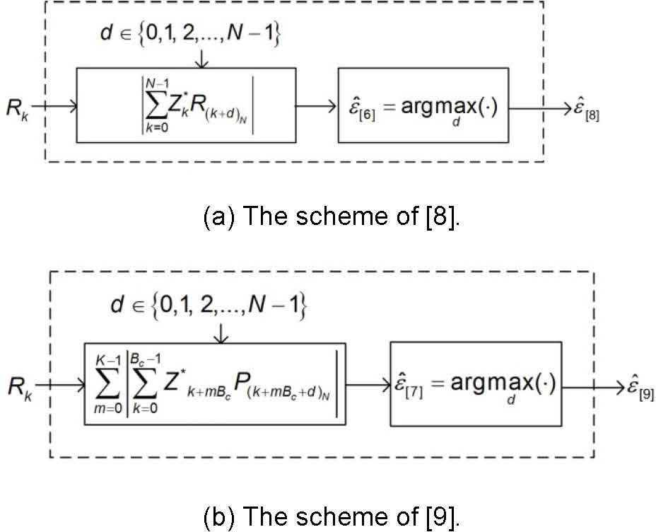
3Conventional schemeIn the conventional scheme of [8], the IFO is estimated by finding an IFO candidate that maximizes the correlation function between the received and local OFDM training symbols in frequency domain as
where d is an IFO candidate in {0,1,⋯, N − 1}, (.)N is the modulo-N operator, and (∙)* is the conjugation operation. Figure 2 shows the normalized correlation values of Eq. 4 as a function of timing offset. From the figure, we can see that the correlation value becomes smaller as the absolute value of timing offset increases. Thus, the scheme of [8] based on the maximum value of the correlation value could be very sensitive to the timing offset.
Normalized correlation value of the scheme of [8] as a function of timing offset.
In the conventional scheme of [9], the correlation operation is performed individually within each CPB block, and then, the correlation values are summated. Here, the CPB Bc is defined by [9]
where nt is a maximum tolerable timing offset of the system, and the timing offset estimation process after the IFO estimation is assumed to guarantee the estimation of the timing offset smaller than nt..
To estimate the IFO, the scheme of [9] calculates the correlation between the known training symbol Zkk=0N−1 and the circularly shifted version of the received training symbol in frequency domain, and then, obtains the IFO estimate ϵˆ7 as
where K = N/Bc. Figure 3 shows the normalized correlation values of Eq. 6 as a function of timing offset. From the figure, we can observe that the correlation value has no zero-crossing point unlike that of the scheme of [8].
Normalized correlation value of the scheme of [9] as a function of timing offset
Figures 4 and 5 show the correlation values of the schemes in [8] and [9] as a function of the integration range when d = ε, Bc = 256, and N = 1024, respectively. As shown in the figures, the correlation of the scheme of [8] oscillates in the presence of the timing offset, which would results in a significant estimation performance degradation. On the other hand, the correlation values of the scheme of [9] increase monotonically as the integration range increases when n0 < Bc overcoming the effect of the timing offset. However, the scheme of [9] has high computational complexity since the correlation values are calculated for all possible values of d.
The correlation values of the schemes in [8] as a function of the integration range when d = ε, N = 1024, and Bc=256.
The correlation values of the schemes in [9] as a function of the integration range when d = ε, N = 1024, and Bc=256.
The correlation function ∑m=0K−1|∑k=0Bc−1Zk+mBc*R(k+mBc+d)N| in the absence of noise has its maximum value when d = ε, and the difference between ∑m=0K−1|∑k=0Bc−1Zk+mBc*R(k+mBc+ϵ)N| and ∑m=0K−1|∑k=0Bc−1Zk+mBc*R(k+mBc+d)N|d≠ϵ becomes larger as the value of N increases. Figure 6 shows the normalized version of ∑m=0K−1|∑k=0Bc−1Zk+mBc*R(k+mBc+d)N| I as a function of d when N = 1024 and ε = 256 as an example. From the figure, we can see that the correlations from the incorrect IFO candidates would not affect the IFO estimation although we summate the frequency-shifted received training symbols with different IFO candidates when the number N of the subcarriers is a large value.
In this paper, we propose an IFO estimation scheme using combined training symbols as shown in Figure 7. Unlike the conventional schemes of [8] and [9] shown in Figure 7(a) and (b), the proposed scheme estimates the IFO in two stages as shown in Figure 7(c). Firstly, we combine the circularly shifted versions of the received training symbol in frequency domain to generate a template signal as
where G is the number of the frequency-shifted training symbols used to construct the template signal. Then, we correlate the template signal with the local training symbol to obtain ϵ˜; as
for d=0,G,…,N/GG, whose example is shown in Figure 8 for G = 5. The correlation operation in Eq. 8 is performed only for N/G+1 IFO candidates reducing the complexity significantly. Finally, G IFO candidates (i.e., ϵ˜;,ϵ˜;+1, and ϵ˜;+G−1) are investigated to choose the final IFO estimate ϵˆp as
for d˜;=ϵ˜;,ϵ˜;+1,ϵ˜;+G−1. The correlation in Eq. 9 is performed only for G IFO candidates, and thus, the proposed scheme performs correlation operation for N/GG+1 times, while the conventional schemes in [8] and [9] performs N times. In addition, we can easily see that the conventional scheme in [9] is a special case (G = 1) of the proposed scheme, where the final step of Eq. 9 is not necessary since the candidate for ϵˆp is ϵ˜; only, and thus, ϵ˜;p=ϵ˜; when G = 1. It is noteworthy that the proposed scheme is applicable to various OFDM systems that utilize training symbols by reducing the number of IFO candidates using a template signal based on the training symbols.
5Numerical resultsTo evaluate the estimation performances of the schemes, we compare the correct estimation probabilities of the proposed and conventional schemes, defined as the probability that the final
IFO estimate equals to ε. We assume the following parameters: N = 1024, Bc = 32, nt=16, ε = 20, and the CP with length of 16 samples.
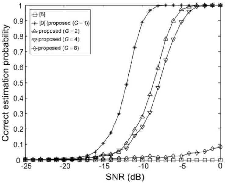
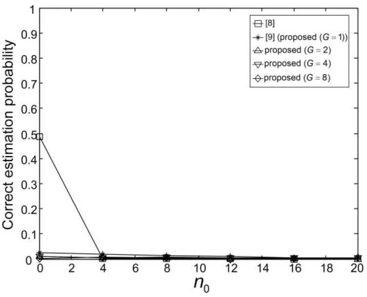
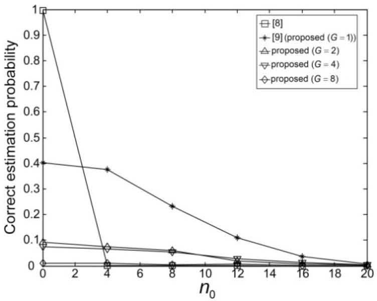
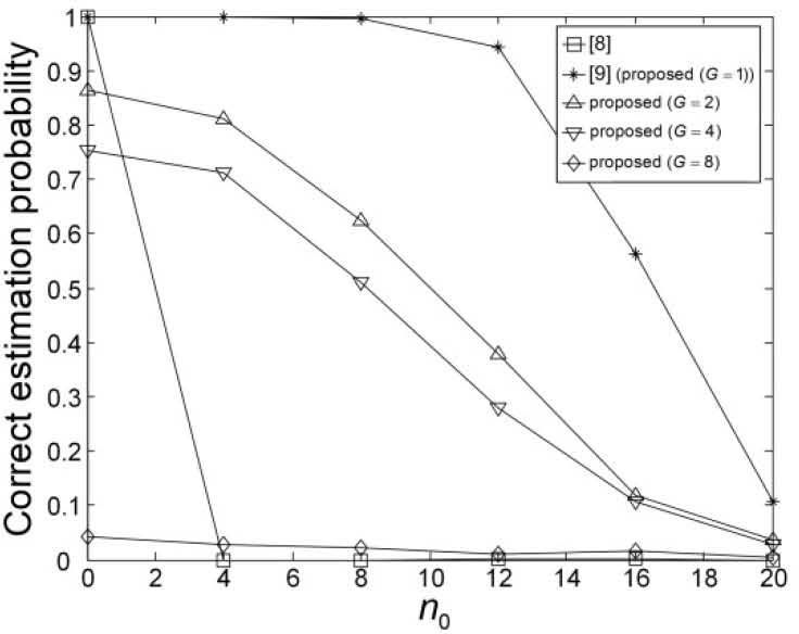
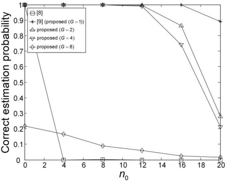
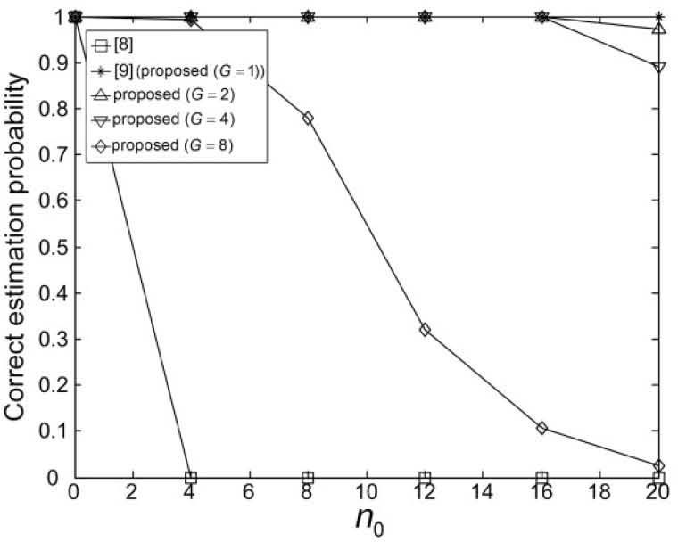
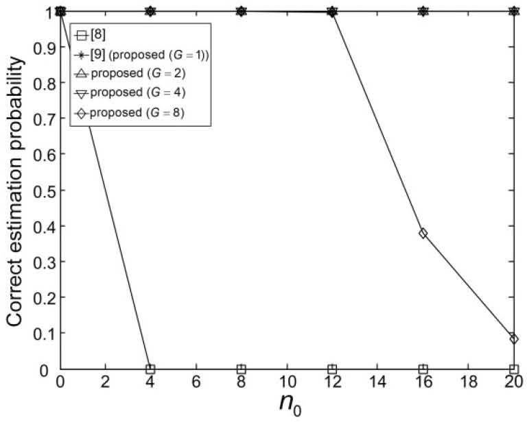
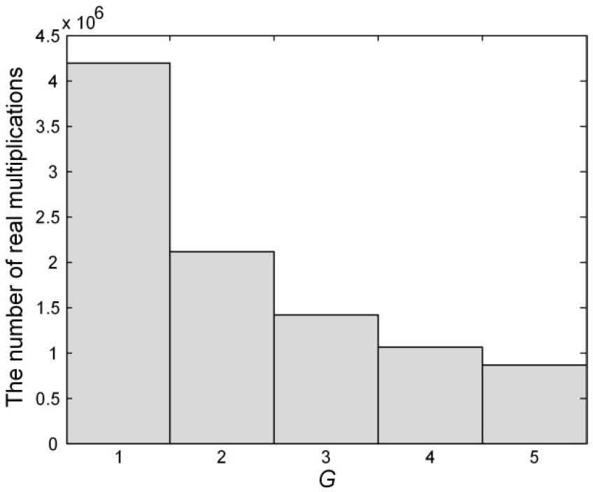
Figures 9-14 show the correct estimation probabilities of the proposed and conventional schemes as a function of SNR, where the SNR is defined as σs2/σw2 with the variance σs2 of the transmitted signal when the timing offset equals to 0, 4, 8, 12, 16, and 20 samples, respectively. Figures 15-20 show the correct estimation probabilities of the proposed and conventional schemes as a function of timing offset when SNR equals to -25, -20, -15, -10, -5, and 0 dB respectively. From the figures, we can see that the scheme of [8] fails to estimate the IFO in the presence of timing offset, meanwhile the scheme of [9] (i.e., the proposed scheme when G = 1) shows the best correct estimation probability performance. The proposed scheme has a degraded correct estimation probability as the value of G increases; however, as shown in Table 1 and Figure 21, the proposed scheme can estimate IFO with much reduced computational complexity. Here, we consider the computational complexity in terms of the number of real additions and the number of real multiplications. A complex addition operation is counted as two real addition operations and a complex multiplication operation consists of two real addition and four real multiplication operations.
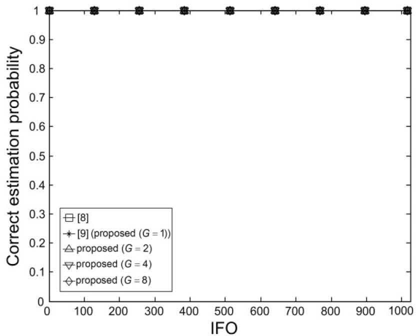
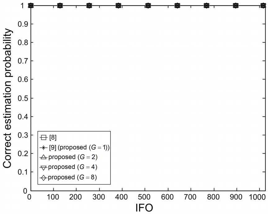
Figures 22 and 23 show the correct estimation probabilities of the proposed and conventional schemes as a function of IFO in the absence of timing offset when the SNR equals to -10 and 0 dB, respectively. From the figures, we can clearly see that the correct estimation probabilities are the same for all IFO values for proposed and conventional schemes, which implies that the proposed and conventional schemes are not a function of the IFO and they provide the unbiased estimation results.
As a practical application of the proposed scheme, we can estimate the SNR of the received OFDM signal as in [10], and then, we can choose a value of G that reduces the computational complexity while keeping the correct estimation probability.
6ConclusionIn this paper, we have proposed an IFO estimation scheme with a reduced complexity by employing template signals consists of multiple frequency-shifted training symbols. The proposed scheme has been shown to provide the tradeoff between the estimation performance and the computational complexity in terms of the correct estimation probability and the number of real multiplications and additions, respectively.
This research was supported by the National Research Foundation (NRF) of Korea under Grant 2014R1A5A1011478 and by the Convergence Information Technology Research Center (C-ITRC) support program supervised by the National IT Industry Promotion Agency (NIPA) under Grant NIPA-2014-H0401-14-1009 with funding from the Ministry of Science, ICT and Future Planning (MSIP), Korea, and by Priority Research Centers Program through the NRF of Korea under Grant 2009-0093828 with funding from the Ministry of Education, Science and Technology.






![Normalized correlation value of the scheme of [8] as a function of timing offset. Normalized correlation value of the scheme of [8] as a function of timing offset.](https://static.elsevier.es/multimedia/16656423/0000001200000006/v2_201505081706/S1665642314716670/v2_201505081706/en/main.assets/thumbnail/gr2.jpeg?xkr=ue/ImdikoIMrsJoerZ+w96p5LBcBpyJTqfwgorxm+Ow=)


![Normalized correlation value of the scheme of [9] as a function of timing offset Normalized correlation value of the scheme of [9] as a function of timing offset](https://static.elsevier.es/multimedia/16656423/0000001200000006/v2_201505081706/S1665642314716670/v2_201505081706/en/main.assets/thumbnail/gr3.jpeg?xkr=ue/ImdikoIMrsJoerZ+w96p5LBcBpyJTqfwgorxm+Ow=)
![The correlation values of the schemes in [8] as a function of the integration range when d = ε, N = 1024, and Bc=256. The correlation values of the schemes in [8] as a function of the integration range when d = ε, N = 1024, and Bc=256.](https://static.elsevier.es/multimedia/16656423/0000001200000006/v2_201505081706/S1665642314716670/v2_201505081706/en/main.assets/thumbnail/gr4.jpeg?xkr=ue/ImdikoIMrsJoerZ+w96p5LBcBpyJTqfwgorxm+Ow=)
![The correlation values of the schemes in [9] as a function of the integration range when d = ε, N = 1024, and Bc=256. The correlation values of the schemes in [9] as a function of the integration range when d = ε, N = 1024, and Bc=256.](https://static.elsevier.es/multimedia/16656423/0000001200000006/v2_201505081706/S1665642314716670/v2_201505081706/en/main.assets/thumbnail/gr5.jpeg?xkr=ue/ImdikoIMrsJoerZ+w96p5LBcBpyJTqfwgorxm+Ow=)


