In this paper an analytical approach is conducted to evaluate the droop control method in an islanding microgrid. Droop control is the key solution for sharing the demand power between generators in autonomous microgrids where there is no support from the electricity distribution grid. In the paper, three important load types are investigated to verify the droop control performance. First, coupling of active power and reactive power is considered in the microgrid and a new method is proposed to facilitate separate control of powers. In the proposed method the effects of droop gains on decoupling of active power and reactive power control, voltage regulation, power oscillation and system stability are studied. In the second load type study, by applying the different types of faults, induction motor characteristics are observed. By simulation results it is shown that the fault intensity and duration will determine how the microgrid attains to fast frequency convergence and how fast protection system operation can improve system stability. In the third case, imbalanced nonlinear load is studied in the microgrid and the influences of embedded controllers on harmonic distortion, system balance and voltage regulation are observed.
The interconnection of small generation systems like solar photovoltaics, micro turbines, fuel cells, wind turbines and energy storage devices to low voltage distribution network will lead to a dynamic power system. These power sources give the capability of decentralized generation and are known as distributed generators (DGs) (Chowdhury & Crossley, 2009; Sumithira & Nirmal Kumar, 2013).
A microgrid which includes local DGs and loads, can operate in two different modes of operation. In interconnected mode it is connected to the main upstream grid, being supplied from or injecting power into it. Other mode is autonomous mode of operation and the microgrid is disconnected from distribution network (Balaguer, Lei, Yang, Supatti, & Peng, 2011; Majumder, Ghosh, Ledwich, & Zare, 2009).
DGs improve the service reliability and decrease the need for future generation expansion planning. Moreover, in concept of islanding microgrid it extends up the possibility of making sources responsible for local power quality factors in a way that is not conceivable with conventional centralized power generation (Fu et al., 2012; Marwali & Keyhani, 2004; Zhengbo, Linchuan, & Tuo, 2011).
Unlike conventional generators which almost exclusively produce 50 or 60Hz electricity, the majority of DGs are connected to the grid via voltage source inverters (Strzelecki & Benysek, 2008). The basic control objective for DGs in a microgrid is to achieve accurate power sharing while regulating of the microgrid voltage magnitude and frequency. Centralized control of a microgrid based on communication infrastructure is also proposed. However, in remote areas with long distance between inverters, it is impractical and costly to use communication link.
Decentralized controllers are investigated to eliminate communication links. Thereby power sharing for microgrid generators is achieved by means of droop controllers. In some studies a static droop compensator is reported for power sharing (Chandorkar, Divan, & Adapa,1993; Katiraei & Iravani, 2006). Droop control is enhanced featuring the transient response performance (Guerrero, De Vicuna, Matas, Castilla, & Miret, 2004). To decrease the active power (P) and reactive power (Q) dependency, droop controllers with virtual frequency–voltage frame (Li & Li, 2011) and virtual output impedance (Chiang, Yen, & Chang, 2001) are also discussed. For nonlinear loads, harmonic based droop controllers are proposed (Borup, Blaabjerg, & Enjeti, 2001; Lee, & Cheng, 2007; Marwali, Jung, & Keyhani, 2004). Although these control methods can improve the overall power quality factors, but they have complexities in adjusting control parameters.
As it can be seen in literature review, there is no comprehensive study of microgrid in presence of important load types and only one kind of load is considered in each article. In this paper microgrid with droop control is analyzed in presence of different kind of loads. Step change in active demand power, dynamic loads such as induction motors in fault condition, and imbalanced harmonic distorted loads are three types of loads considered in this paper. Load characteristics effects on power quality factors are observed in simulation results. These studies can properly comprise the most important loads being utilized in a sample microgrid.
2Droop controlDroop control for a sample microgrid is considered in direct-quadrature-zero reference frame which facilitates control process by transforming time variant quantities of voltage and current in three phases reference frame to direct current (dc) quantities. Figure 1 illustrates the alternative current (ac) three phases (abc) and direct-quadrature-zero (dq0) coordinate frames.
Reference voltage for pulse width modulation (PWM) signals of inverters is generated by three back to back power, voltage and current controllers (Marwali & Keyhani, 2004; Pogaku, Prodanovic, & Green, 2007). Figure 2 shows a DG unit connected to the microgrid by inverter. Output filter (LfCf) and coupling inductance (Lc) are connected before the terminal bus. It is assumed that the input source of inverter is an ideal dc link. Inner controllers are further discussed.
2.1Power controllerDroop control scheme mimics the operation of governor and exciter in synchronous generators and determines output frequency and voltage of DGs according to the active and reactive powers derived from their terminals. In order to determine frequency and voltage by droop equations, instantaneous active and reactive powers (p and q) should be calculated from the generator output voltage and current (v0 and i0) as they are shown in Figure 2. i is the current of coupling inductance where its values in dq0 reference frame are id and iq, vod, voq, iod and ioq are the values of output voltage and current variables in dq0 reference frame along d-axis and q-axis respectively.
According to Eqs. (3) and (4) to derive P and Q, above quantities should be passed through low pass filter in which ωf is the cut-out frequency. Reference voltage (vod*) and frequency (ω) of power controller can be obtained by Eqs. (5) and (6) respectively.
In above equations ωn and Vn are nominal frequency and voltage of microgrid. K1 and K2 are droop gains; these gains relate to economic and technical features of each DG unit. Droop gains are kept the same for all generators in this paper for simplicity. Reference voltage along the q-axis (voq*) is set to be zero in order to have positive sequence components in three phase system.
According to droop characteristic, frequency of each DG changes continuously by variation in its active power. When a disturbance occurs, frequency will reach the steady state amount after transition time. DGs have different frequencies in compare to each other during transient time because they face different impedances. As one frequency is possible for generators of a microgrid, active power is divided between DGs in a way that produce same frequency for them. Therefore DGs should produce same P in same active power droop gain (K1).
2.2Voltage and current controllersReference voltage and frequency generated by power controller are fed to back to back voltage and current controllers (Fig. 3) to create reference currents (id* and iq*) and reference inverter voltages (vid* and vid*) in dq0 reference frame. Both controllers are designed to reject high frequency disturbances and provide adequate damping for the output filter. Inner proportional-integral (PI) controllers guarantee zero steady state error and improve system transient response. Also feed-forward loops isolate DGs from load disturbances. F is the current feed-forward gain and it has not unit.
3Simulation resultsObserving DGs reactive power when a step change is occurred in active power, induction motor characteristics in fault conditions and power quality evaluation for nonlinear load are three load scenarios applied to a sample microgrid. Matlab simulations evaluate the control scheme which was discussed in previous section.
Figure 4 shows the microgrid single phase schematic. It contains three buses with a DG in each bus. Network and controller parameters like resistance and reactance of lines, inverter output filter, switching frequency and droop gains are given in Table 1. fs is the inverter switching frequency. Coefficients of inner PI controllers are tuned in each section by trial and error method.
In order to observe P and Q dependency, a step change in the demand active power is made by a controlled current source in bus 1 as it can be seen in Figure 5. All the active power requested by network and loads is 12kW before the demand change. After 1s 9kW of total P is increased approximately.
Figures 6 and 7 show active and reactive powers generated by DGs in each three buses. Three DGs produce equal P in steady state time because their droop gains have the same value. But in transient state the active power of DG1 has much greater value with respect to two other DGs. It should be considered in protection system design.
Although the change in active power is made in bus 1, reactive power produced by each DG has noticeable change. In microgrids with resistive lines P and Q are mainly coupled to each other. In order to mitigate the coupling of DGs generated active and reactive power, droop gain should be tuned as well as maintaining system stability. Increasing the reactive power droop gain is considered as a solution to improve the power sharing performance. In Figures 8 and 9, active and reactive powers generated by DGs are shown for new reactive power droop gain (K2=0.6) which is chosen by trial and error method.
In this case active powers of DGs are the same as before but reactive powers are influenced less than previous case from change in the active power demand. Although P and Q are properly decoupled by increasing K2, but it consequences oscillation in Q and for higher values of reactive power droop gain it contributes to instability and low voltage regulation.
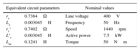
3.2Induction motor in fault conditionIn order to study dynamic loads in a microgrid with droop control, induction motor as the most common industrial load is chosen to be examined. Motor characteristics like stator and rotor current and rotor speed are observed in fault conditions. Single phase schematic of the circuit is shown in Figure 10 where M1 and M2 are induction motors. Motor parameters are also given in Table 2 where rs and Ls are stator resistance and inductance. r′r and L′r are rotor resistance and inductance. Lm is the magnetizing inductance.
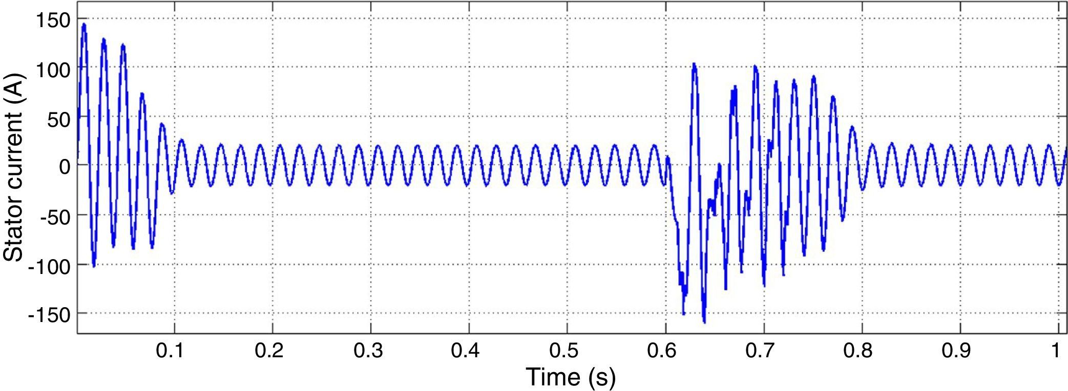
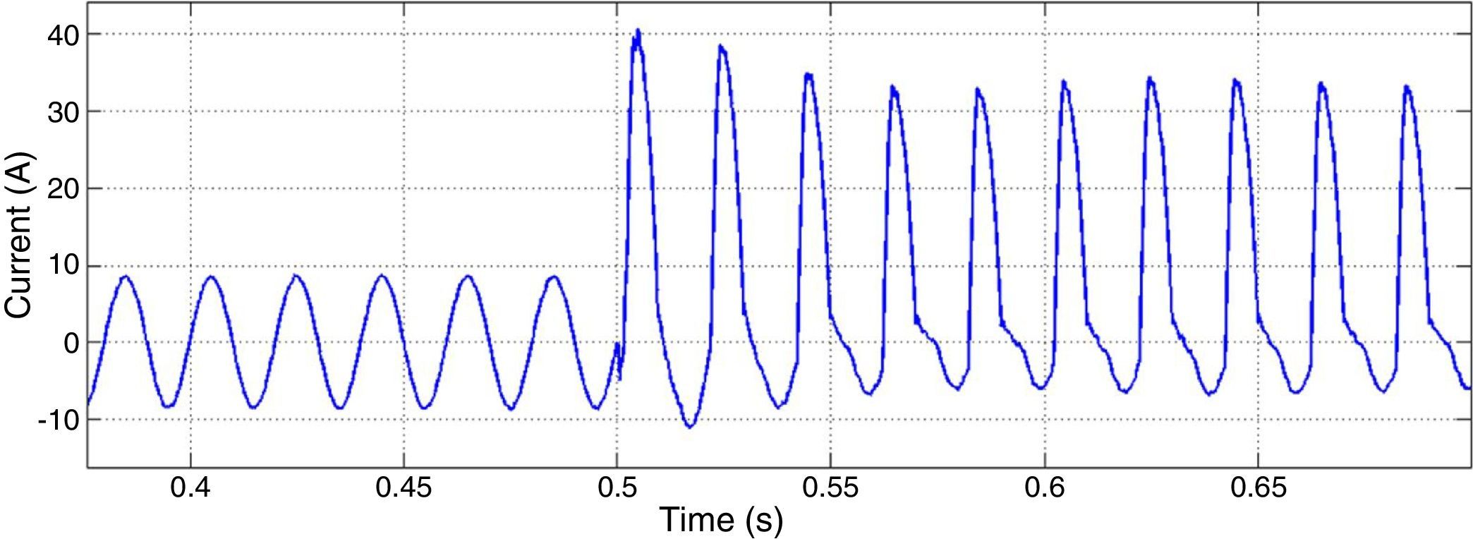
After 0.6s of the motor starting, a two phases to ground fault is occurred in bus 1. After 3 cycles the fault is cleared. Figure 11 shows motor 1 stator current as one of motor characteristics. It can be seen that voltage and frequency controllers have the capability of maintaining the system stability after fault clearance.
By increasing the fault extremity, 3 phases to ground fault is applied to the microgrid. All the other conditions are kept the same as the previous fault. As it can be seen in Figure 12, after fault clearance, controllers are failed to maintain system stability.
The main cause for instability is due to the extreme demand of current and power. According to the droop characteristic, DGs frequency will fail to converge because they generate large amount of active power and their generation difference is remarkable. Reference frequency determined by power controllers for one of three DGs is shown in Figure 13.
To enhance the microgrid stability in three phases to ground fault, fast fault clearance is proposed as a solution. If the protection system detects the fault and disconnects the part where short circuit is happened, system stability will be procured fast. Figure 14 shows the stator current of the motor when the fault is cleared fast.
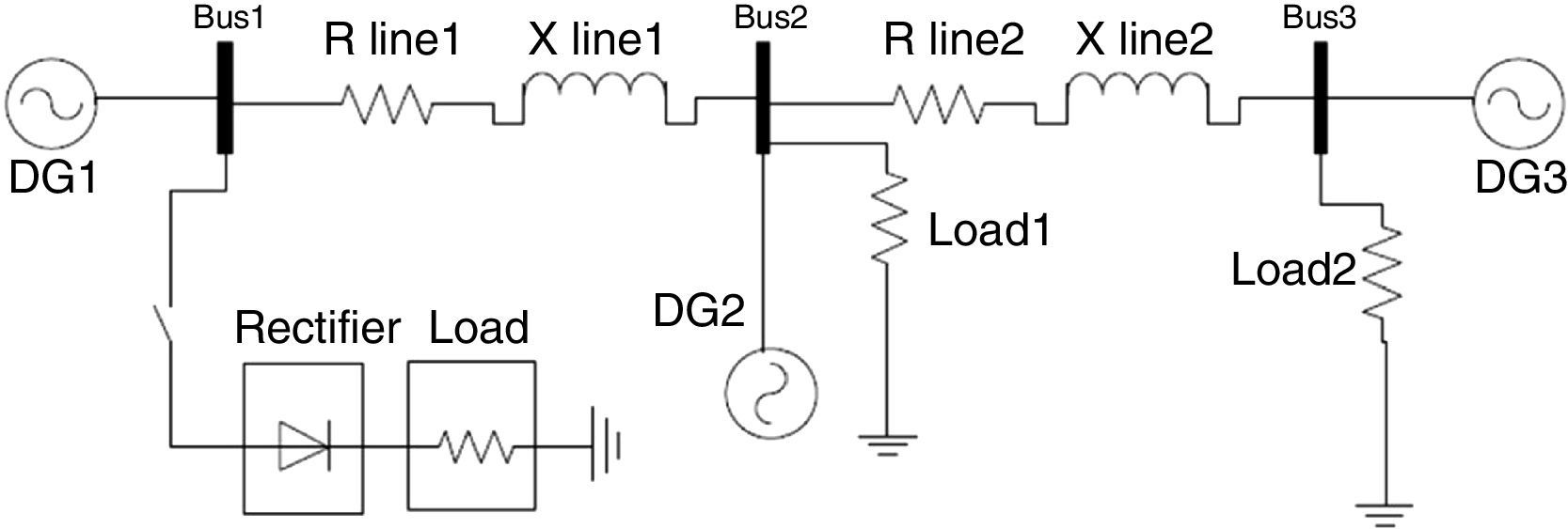
3.3Nonlinear loadIn this part imbalanced harmonic distorted load is studied in the microgrid with droop control. Considering Figure 15, after starting the simulation a two-phase rectifier is connected to bus 1. This load is nonlinear and imbalanced.
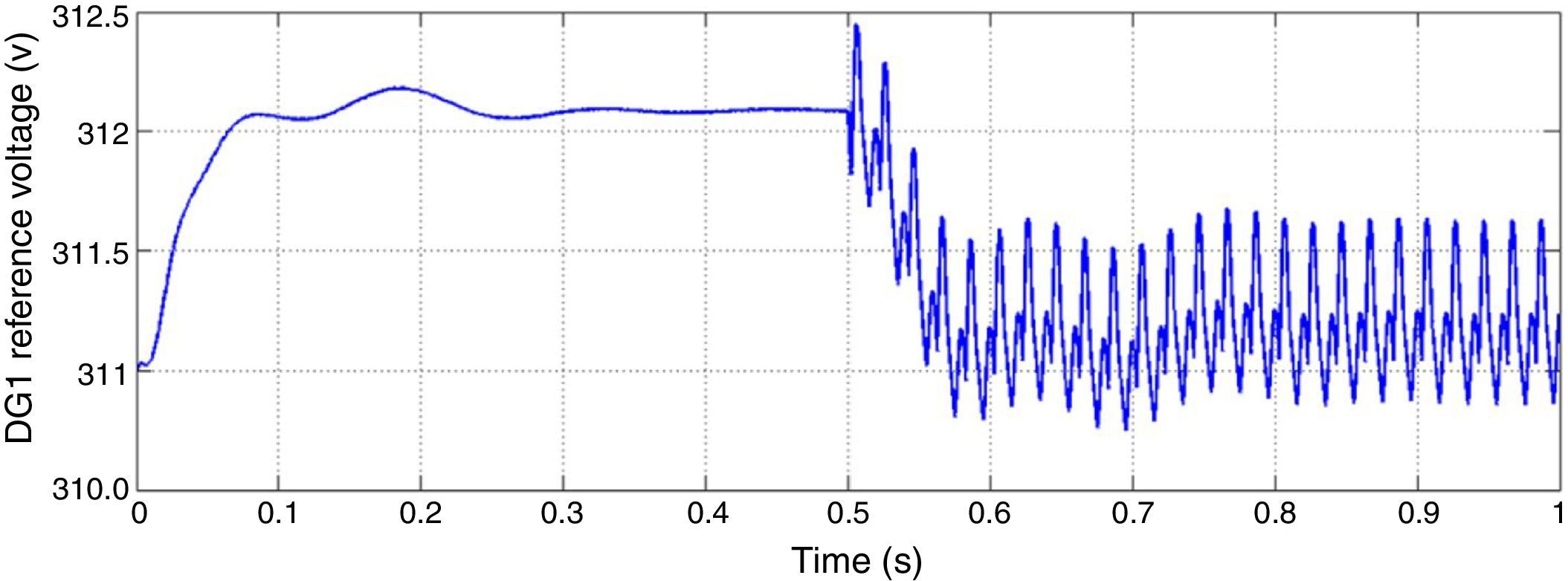
Figure 16 shows reference voltage of d-axis created by DG1 inner controllers in dq0 frame. After switching the rectifier, oscillation is visible in this figure. Large deviations in reference voltage absolutely for the DG of bus 1 where the nonlinear load is located are noticeable. This contributes to low voltage regulation because output voltage fails to track the reference voltage due to its fast deviations.
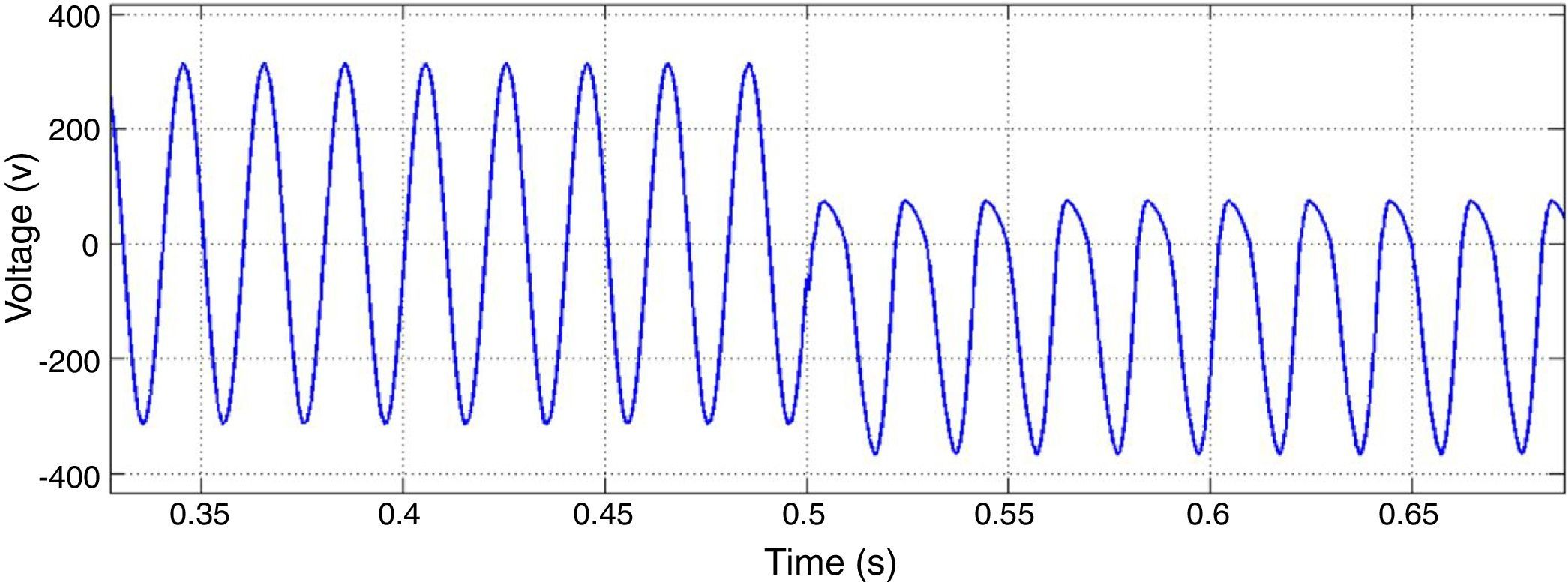
PI controllers of inner voltage and current controllers are tuned to be operative in zero frequency in dq0 reference frame. In presence of imbalanced harmonic distorted loads there would be other harmonic components such as 50Hz caused by asymmetry. So as it can be seen in Figures 17 and 18, voltage and current of DG1 have high total harmonic distortion (THD), neutral point deviance and low voltage regulation.
According to the simulation results, the impact of load type on droop control method performance was analyzed. It was shown that the reactive power sharing of inductive loads can be improved by the proposed method in which the reactive power droop can is increased with regard to the system stability. This approach facilitates the decoupling of active and reactive power generation of power sources.
An in depth discussion was provided with regard to the frequency convergence in islanding microgrids. It was shown that the main impact of fault occurrence on the system stability is due to large frequency deviation of generators with respect to each other. Fast fault clearance was introduced as a solution for this problem.
Finally, for the nonlinear loads it was concluded that the main cause for the controller failure is due to the operation mechanism of back-to-back voltage and current controllers. They are designed to be applied on voltage and current variables in dq0 reference frame. In presence of harmonic distorted loads, time variant (non dc) component would be appeared for control variables. Therefore, the embedded PI controllers would fail in creating zero steady state error.
4ConclusionDroop control based autonomous microgrid was analyzed in this paper in presence of different types of loads. Simulation results were shown for different case studies. Dependency of active and reactive powers generated by DGs was considered as an important challenge in isolated microgrids. Increasing reactive power droop gain was proposed as a solution and its effects on power quality factors were shown.
In second study, induction motor characteristics in fault condition were shown. It was concluded that the fault intensity and duration determine how the microgrid attains to fast frequency convergence and fast response of protection system can increase the system stability. Finally nonlinear load as an important conventional industrial consumer was verified in the microgrid. Simulation results showed that the main cause of high THD, system imbalance and low voltage regulation is due to non-zero frequency components of control parameters of inner PI controllers in dq0 reference frame.
Conflict of interestThe authors have no conflicts of interest to declare.
Peer Review under the responsibility of Universidad Nacional Autónoma de México.


