This paper analyzed the chaotic behaviors and vibration phenomenon of a flexible rotor with different mass and bearing number supported by ultra short aero-lubricated bearing (USAB) system. The hybrid method combined with differential transformation method and finite difference method are proposed and used to calculate gas pressure distribution of USAB system. The results are shown that system exist chaotic motions over the specific ranges, and the maximum Lyapunov exponent is positive as chaos occurred.
Ultra short aero-lubricated bearing (USAB) system is different from general gas-lubricated bearings (Ascanio, Cavaa, Chicurelb, & Reséndizc, 2007) due to the limit of length-diameter ratio. USAB system is characterized by low frictional losses and low noise under rotation. As a result, it is frequently employed within precision instruments, where it yields zero friction when the instruments are used as null devices, and within high-speed requirements. Because of the rotational speed of the rotor can be operated over 106 rpm, the stability of flexible rotor dynamics is one of the most important and key factors for the design of USAB systems. So, how to increase the stability of rotor systems and avoid the appearance of non-periodic motion becomes the major execution of this paper.
Recently, dynamic responses of bearing systems were analyzed and the bifurcation phenomenon and dynamic behavior of rigid rotor supported by noncircular aero-lubricated bearing system were studied by Rashidi, Mohammadi, & Bakhtiarinejad, 2009; Rashidi, Mohammadi, & Bakhtiarinejad, 2010. The finite element method and Runge-Kutta method are applied to solve the Reynolds’ equation and rotor dynamic equations, respectively. The results show that the key parameters including rotor mass and bearing number are dominated to bifurcation and responses of rotor behaviors. Meanwhile, those reponses includes different types of motions under different real operational conditions.
For the analysis of USAB, Zhou, Meng, Chen, & Zhang (2009) analyzed the bifurcation of ultrashort self-acting air journal bearings for MENS. This bearing system is modeled as a rigid rotor supported by bearing forces as a result of gas viscosity and rotational speed. The nonlinear behaviors of micro gas journal bearings are further studied by Wang (2010a) and the bifurcation and non-periodic motion of rigid rotor are also solved. The results show that the rotor exhibits complex dynamic behaviors comprising periodic, sub-harmonic, and quasi-periodic responses at different values of the rotor mass and bearing number, respectively.
For the studies of relative short bearings, in 2010, Wang (2010b) analyzed the bifurcation behavior and nonlinear dynamics of a flexible rotor supported by a relative short spherical gas bearing system. The analytical results reveal several types of dynamic behavior including chaotic responses of the rotor center and the journal center. Furthermore, the results reveal the changes which take place in the dynamic behavior of the bearing system as the rotor mass and bearing number are increased.
In the present paper, the chaotic (Pérez, 2008) and bifurcation response of a flexible rotor supported by two ultra short aero-lubricated bearings are studied. In order to analyze the bearing system, the Reynolds’ equation are used to model the time-dependent motions of the rotor center. Then, the hybrid method combined with differential transformation method (DTM) and the finite difference method (FDM) are applied to solve the Reynolds’ equation. The dynamic response of the rotor and journal centers are simulated and analyzed for non-dimensional rotor masses and bearing number in the ranges 0.01∼0.85 and 1.0∼7.5, respectively.
2Mathematical modeling2.1Governing equationsThe application for high rotational speed more than 106 rpm can be used by ultra short aero-lubricated bearing (USAB) system and the stability of this system is focused to be analyzed. An USAB is different from general air bearing system and the ratio of bearing length to diameter (L/D) is less than 0.1
The USAB systems are designed and assumed as following:
- •
The flow is assumed isothermal and the gas flow in and out of the sides of the bearing is neglected.
- •
The gas viscosity is assumed to be constant.
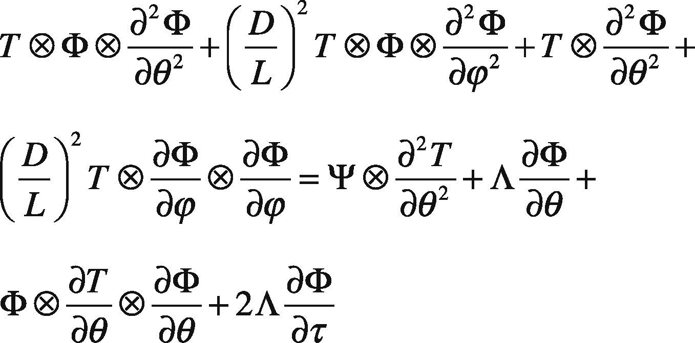
The air pressure distribution between the shaft and the bushing in USAB system (Wang & Yau, 2013) is modeled by the Reynolds’ equation shown in Eq. (1).
Where D is the diameter of bearing, L is the length of bearing, Λ is the bearing number; θ and Φ are the coordinates in the circumferential and axial directions, respectively. Φ=PT, P is the non-dimensional pressure corresponding to the atmospheric pressure; T is the non-dimensional film thickness between the rotating shaft and the bushing, corresponding to the radial clearance.
The air pressure distribution is fulfilled the following boundary conditions:
- •
Air pressure on both ends of the housing is equal to the atmospheric pressure and is a periodic function for θ.
- •
Air pressure is an even function for Φ, and is continuous at Φ= 0.
In the transient state, the flexible rotor is supported by the USAB system, and equations of motion of rotor center X2*,Y2* and journal center X3*,Y3* can be written in Cartesian coordinate form as
Where Kp is the stiffness of the shaft, ρ and ω are the mass eccentricity and rotational speed of the rotor, respectively.
For balancing forces, the resultant forces acting on the journal center in the horizontal and vertical directions are applied to journal center. It can be given by
The following transformations and non-dimensional groups can be introduced:
Substituting the transformations given in Eqs. (6) and (7) into Eqs. (2)–(5), and introducing the non-dimensional groups defined in Eq. (7), Eqs. (2)–(5) become
The computation procedure begins by specifying an initial static equilibrium state. The initial displacement of the rotor corresponds to the static equilibrium position and defines the gap T. The initial velocity of the rotor is assumed to be zero. The iterative calculation procedure can be summarized as follows:
- •
Step 1: Following a time increment, the new values of acceleration, velocity, and displacement of rotor are obtained by:
- •
Step 2: The displacements of the rotor center obtained from Step 1 are substituted into Eqs. (8) and (9). The displacements of the journal center can then be determined and the corresponding change in the value of T can be calculated. Substituting the new value T into Eq. (1) gives the new pressure distribution between the shaft and the journal.
- •
Step 3: The internal force can then be estimated by integrating the pressure distribution obtained from Step 2.
- •
Step 4: The displacement and velocity values computed in Step 1, the pressure distribution calculated in Step 2, and the internal force obtained in Step 3 are taken as the new initial conditions. Using this new set of conditions, the calculation procedure returns to Step 1 to compute the changes in the bearing system during the next time interval.
For solving Eq. (1), it is discretized initially by central-difference scheme in the θ and ϕ directions and is then discretized once again using the implicit-back-difference scheme in the time domain. Note that for simplicity, a uniform mesh size is used. Eq. (1) can be transformed into the following form:
The pressure distribution at each time step can then be obtained using an iterative calculation process.
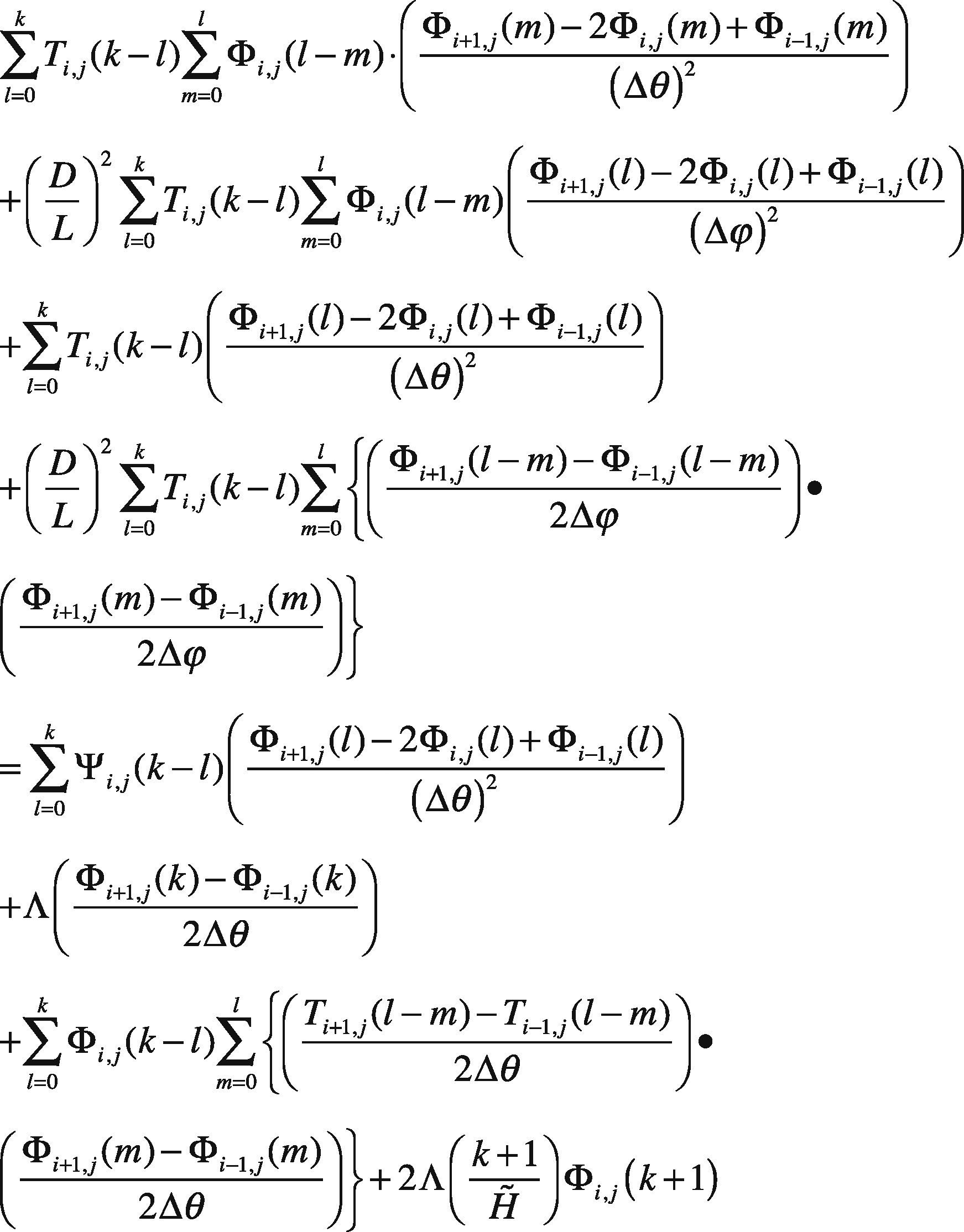
In order to compare the numerical results, the hybrid method is proposed in this study and is commenced by using the differential transformation method (DTM) (Wang & Yau, 2013) to discretize the Eq. (1) with respect to time. Eq. (1) becomes
where
Then, finite difference method (FDM) is applied to discretize Eq. (16) with respect to the θ and ϕ directions. Substituting (17) into (16) yields
where H˜ is time step value, i and j are the coordinates of the node position, and k indicates the kth term.
Air pressure distribution is obtained for each time interval, and the motions of the rotor center are computed using an iterative procedure.
In this study, the data generated by procedures described above are used to obtain power spectra, Poincaré maps, bifurcation diagrams and Lyapunov exponents with which to analyze the nonlinear dynamic response of the USAB system over representative ranges of non-dimensional rotor mass and bearing number.
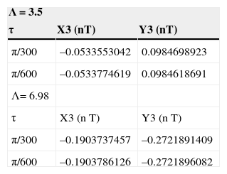
3Results and discussion3.1Numerical analysisThe numerical results for the orbits of the journal center are calculated by the FDM and hybrid method (FDM&DTM) shown in Table 1. It is observed that a good agreement exists between the two sets of results. However, it can be seen that journal orbits obtained by hybrid method have better precision than FDM under all the considered conditions and therefore represents a more appropriate method for the responses of the USAB system.
The Poincaré map data calculated by the hybrid method using different time step values, H˜, for bearing number values are shown in Table 2. The journal center orbits are in agreement to approximately 5 decimal places for the different time steps, H˜ for a given rotor mass and bearing number.
Comparison of Poincaré maps of journal center with different values of Λ and H˜ by hybrid method at m˜r = 0.26.
| Λ = 3.5 | ||
|---|---|---|
| τ | X3 (nT) | Y3 (nT) |
| π/300 | –0.0533553042 | 0.0984698923 |
| π/600 | –0.0533774619 | 0.0984618691 |
| Λ= 6.98 | ||
| τ | X3 (n T) | Y3 (n T) |
| π/300 | –0.1903737457 | –0.2721891409 |
| π/600 | –0.1903786126 | –0.2721896082 |
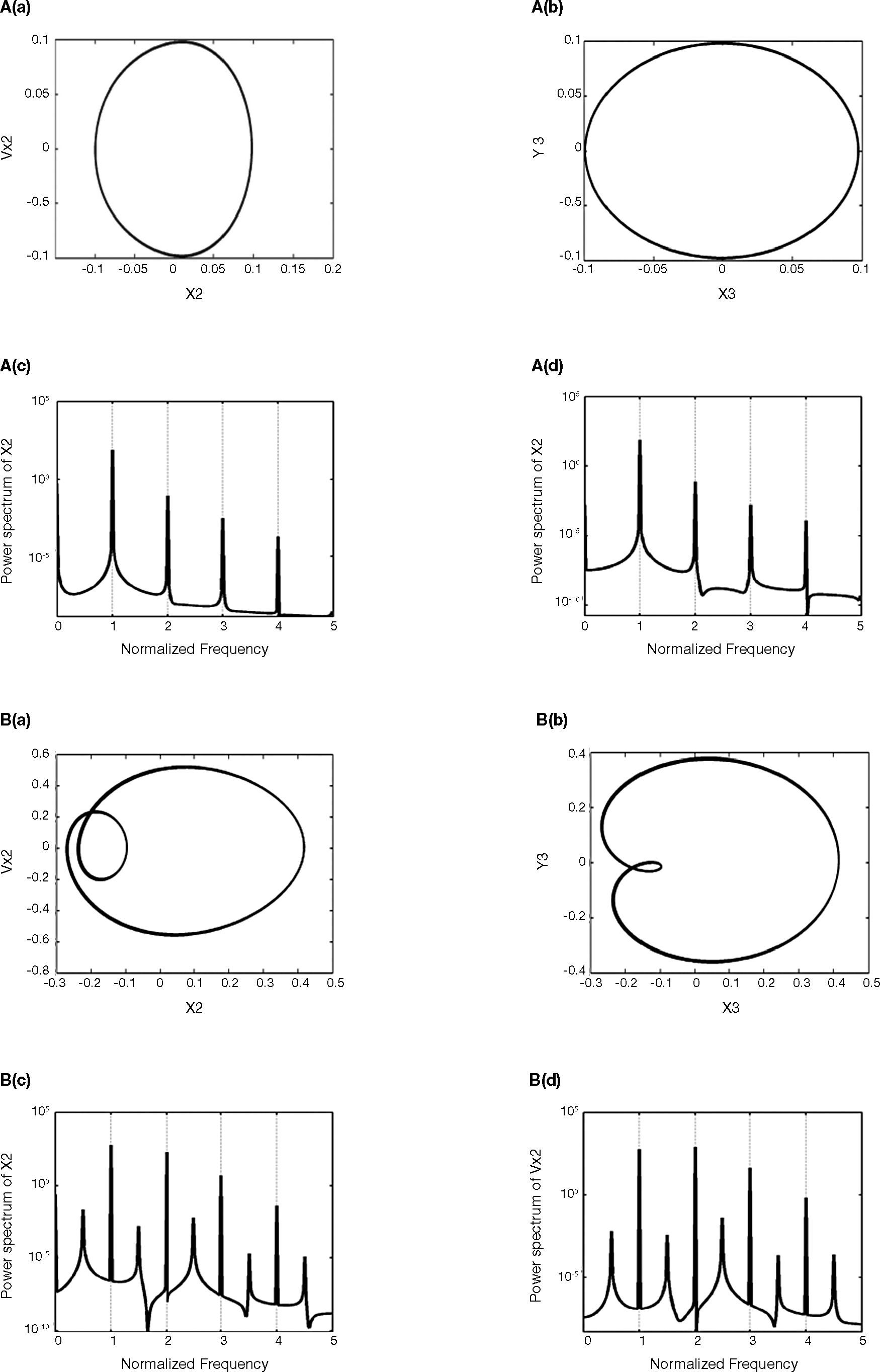
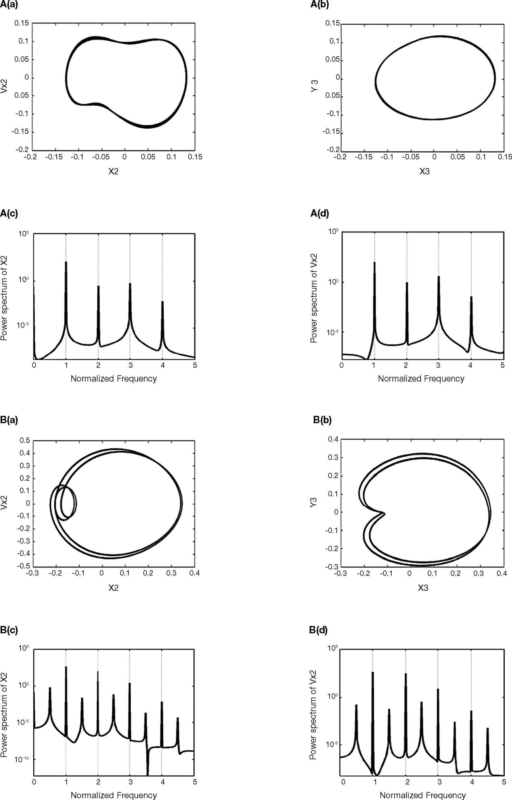
The results show that the dynamic orbits of the rotor and journal center are regular at a low value of the rotor mass (m˜r = 0.26, 0.497, 0.5165, 0.552) shown in Figs. 1A-D, and also proved from the power spectra. But system becomes irregular at m˜r = 0.5525, and the rotor and journal centers perform non-periodic motion simultaneously in both the horizontal and the vertical directions shown in Fig. 1E. At rotor mass of m˜r = 0.71 and 0.843, the rotor and journal center resorts to a regular periodic motion shown in Figs. 1F and G.
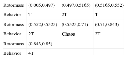
3.3Bifurcation analysis for rotor massFigure 2 shows the bifurcation diagrams for the rotor center displacement in the horizontal and vertical directions as a function of the non-dimensional rotor mass in the range 0.005 to 0.85. Figures 3A-G present the Poincaré maps of the rotor and journal centers trajectories at m˜r = 0.26, 0.497, 0.5165, 0.552, 0.5525, 0.71, and 0.843, respectively. In Figure 2, it can be seen that the rotor center performs T-periodic motion over the rotor mass range 0.005 ≤ m˜r < 0.497 and proved by Figure 3A. The T-periodic motion becomes unstable at m˜r = 0.497 and is replaced by sub-harmonic with a period of 2T motion (Fig. 3B). This sub-harmonic behavior persists over 0.497 ≤ m˜r < 0.5165. For rotor mass in the range 0.5165 ≤ m˜r < 0.5525, the rotor and journal center repeats T→2T motion (Figs. 3C-D). As the rotor mass further increased to 0.5525, system becomes to chaos shown in Figure 3E, and behaved over 0.5525 ≤ m˜r < 0.71. Finally, the rotor is stabilized as the rotor mass over 0.71, and also behaves 2T-periodic and 4T-periodic over 0.71 ≤ m˜r < 0.843 and 0.843 ≤ m˜r < 0.85, respectively shown in Figures 3F and G.
Figure 4 shows that the maximum Lyapunov exponent has a positive value when equals to 0.5525, and also indicates that the system has a chaotic response. Meanwhile, over the intervals 0.5525 ≤ m˜r < 0.71 shown in Figures 2, 3E and 4E, the system behaves non-stable behavior and also should be avoided to operate under these parameters.
Table 3 summarizes the motions performed by the rotor center for rotor mass values in the interval 0.005 ≤ m˜r ≤ 0.85.
3.4Rotor orbits, phase trajectories and power spectra analysis for bearing numberIn Figures 5A and B, the results show that the dynamic orbits of the rotor and journal center are regular at specific value of bearing number (Λ = 3.5 and 5.07) and also verified by the power spectra analysis. Then, USAB system becomes non-periodic and irregular at Λ = 6.51, and the rotor and journal centers perform non-periodic motion shown in Figure 5C. At bearing number of Λ = 6.98, the rotor and journal center in both the horizontal and the vertical directions resort to a regular periodic motion shown in Figure 5D.
3.5Bifurcation analysis for bearing numberFigure 6 plots the bifurcation diagrams for the rotor center displacement in the horizontal and vertical directions as a function of the bearing number Λ in the range 1.0 to 7.5. Figures 7A-D present the Poincaré maps of the rotor and journal centers trajectories at Λ = 3.5, 5.07, 6.51, and 6.98, respectively. In Figure 6, it can be seen that the rotor center performs T-periodic motion over the bearing number range 1.0 ≤ Λ < 5.07 and proved by Figure 7A. The T-periodic motion changes to 2T-periodic motion at bearing numbers of Λ = 5.07 (Fig. 7B). This 2T-periodic behavior persists over 5.07 ≤ Λ < 6.51. As the bearing number is further increased to 6.51, USAB system becomes to chaos shown in Figure 7C, and behaved over the range of 6.51 ≤ Λ < 6.98. Finally, the rotor is transferred to stable situation over the bearing number range 6.98 ≤ Λ ≤ 7.5 and also behaves T-periodic motion shown in Figure 7D.
When the chaotic motion occurs, the maximum Lyapunov exponent has a positive value (as Λ equals 6.51) shown in Figure 8C and equals zero, which means system behaves periodic motion over the intervals 1.0 ≤ Λ < 6.51 and 6.98 ≤ Λ ≤ 7.5 shown in Figures 8A, B and D. Table 4 summarizes the motions performed by the rotor center for bearing number values in the interval 1.0 ≤ Λ ≤ 7.5.
This paper has studied the USAB system for rotor vibration and bifurcation behavior by the finite difference method (FDM) and hybrid method. The system dynamic orbits, power spectra, bifurcation, Poincaré maps, and maximum Lyapunov exponents have revealed the presence of a complex behavior comprising periodic, sub-harmonic, and chaotic responses of the rotor and journal centers. The results of this study provide an understanding of the dynamic behavior of USAB systems characterized by different rotor masses and bearing numbers. Specifically, the numerical results shown that the proposed hybrid method is more suitable than FDM for USAB system and can be obtained higher and better precision than other schemes. On the other hand, the results have shown that system occurs chaotic motions at specific rotor mass and bearing number and should be avoided when USAB system is designed.
The financial support of this research was provided by National Science Council of R.O.C., under the projects No. MOST-102-2221-E-167 -035 and MOST-103-2221-E-167 -011 are greatly appreciated.


