


The IEEE 802.11e EDCA (Enhanced Distributed Channel Access) is able to provide QoS (Quality of Service) by adjusting the transmission opportunities (TXOPs), which control the period to access the medium. The EDCA has a fairness problem among competing stations, which support multimedia applications with different delay bounds. In this paper, we propose a simple and effective scheme for alleviating the fairness problem. The proposed scheme dynamically allocates the TXOP value based on the delay bounds of the data packets in a queue and the traffic load of network. Performance of the proposed scheme is investigated by simulation. Our results show that compared to conventional scheme, the proposed scheme significantly improves network performance, and achieves a high degree of fairness among stations with different multimedia applications.
The widespread use of multimedia applications requires new features such as high bandwidth and small average delay in wireless LANs [1]. Unfortunately, the IEEE 802.11 medium access control (MAC) protocol cannot support quality of service (QoS) requirements [2-4]. In order to support multimedia applications with tight QoS requirements, the IEEE 802.11e has been standardized [5]. It introduces a contention-based new channel access mechanism called enhanced distributed channel access (EDCA) [4-6]. The EDCA supports QoS by introducing four access categories (ACs). To differentiate the ACs, the EDCA uses a set of AC specific parameters: minimum contention window CWmin[i], maximum contention window CWmax[i], and arbitration interframe space (AIFS) AIFS[i] for AC i (i=0, …, 3). Furthermore, the EDCA introduces a transmission opportunity (TXOP). The TXOP is the time interval. A station can transmit multiple data packets consecutively until the duration of transmission exceeds the specific TXOP limit.
In the EDCA, stations are allocated the same TXOP limit value. When they have identical multimedia traffic application, fair bandwidth allocation is expected. However, if stations support multimedia traffic applications with different QoS requirements, fairness problem arises. This problem is explained in detail in Section 2.
In order to support multimedia traffic, many schemes have been proposed in the literature [7-12]. However, the previous schemes still have several problems. First, some of them use analytical models to calculate the QoS metrics which are usually derived based on a few impractical hypotheses. They do not reflect the characteristics of multimedia traffic. Therefore, they are always inaccurate and clearly not applicable to realistic environments [7,8]. Second, some require feedback information from stations to consider the dynamic behavior of multimedia traffic, but the feedback cannot provide an appropriate indication to the current network load conditions in a real-time manner [9,10]. Finally, others proposed very simple schemes to allocate the TXOP limit without considering the QoS requirements of multimedia traffic. A distributed optimal (DO) TXOP scheme uses the throughput information [11]. In the DO TXOP scheme, each station measures its throughput and compares it with the target throughput. If the measured throughput is higher than the target value, the station reduces its TXOP limit; otherwise, it increases its TXOP. A threshold-based dynamic (TBD) TXOP scheme dynamically adjusts the TXOP limit according to the queue length and the pre-setting threshold (THqueue) [12]. Each station has two TXOP limit values: low (TXOPmin) and high TXOPs (TXOPmax). As shown in Figure 1, if the queue length (Q_Len) is below the threshold, the TXOP limit is fixed at the low value; otherwise, the TXOP limit is set to the high value. It is as follows:


It is hard for the stations in the TBD and DO TXOP schemes to have adequate TXOP limit since the both schemes allocate the TXOP limit based on only one parameter: the pre-setting threshold in the TBD TXOP scheme and the target throughput in the DO TXOP scheme. And the TBD and DO TXOP schemes do not take into account the traffic load. Therefore, at high loads, all the stations in the both schemes have large TXOP limit. On the contrary, at light loads, they have small TXOP limit.
In this paper, we propose a simple and effective scheme for alleviating the fairness problem. The proposed scheme dynamically allocates the TXOP limit based on the delay bound and traffic load. Therefore, we call the proposed scheme ATA (Adaptive TXOP Allocation) scheme. In the proposed scheme, the QAP (QoS Access Point) transmits the degree of the network load to stations through a beacon frame. After receiving the beacon frame, each station independently decides its own TXOP limit value. First, a station checks the delay bound of each data packet in the queue, and allocates its TXOP value to guarantee the delay bounds of all the packets in the queue. Then, the station increases its own TXOP value when the traffic load is low.
The paper is organized as follows. The fairness problem is presented in Section 2. In Section 3, the proposed ATA scheme is explained in detail. In Section 4, we discuss simulation results. Finally, we conclude in Section 5.
2Fairness problemThe DO and TBD schemes suffer from the fairness problem since stations support multimedia application service with different QoS requirements. Fairness is an important property of a MAC layer for improving QoS. Here, we analyze the fairness problem of the previous schemes.
The delay bound normally refers to the end-to-end delay bound. And the residual delay bound refers to the residual time interval of the delay bound at a station. Hereafter, we will use the term delay bound to refer to the residual delay bound.
If QoS requirements of each station are same, no problem occurs, because bandwidth is allocated fairly. If each station supports multimedia application service with different QoS requirements, fairness problem occurs. The delay bound of a station depends on the multimedia traffic characteristics. And the traffic has widely varying characteristics. Therefore, stations may have different delay bounds. In this environment, if stations transmit data packets in their queues to receivers without additional mechanisms, the fairness problem between the stations with short and long delay bounds arises. With long delay bound, a station can have many transmission attempts within its own delay bound. Therefore, its transmission can be successful by satisfying its delay bound with high probability. On the contrary, a station with short delay bound can have few transmission attempts and can be successful with low probability. As the delay bound of packets is not satisfied, a receiver discards them, thereby lowering performance of multimedia traffic. Thus, stations with long delay bound always have better performance than those with short delay bound. This causes fairness problem among stations with different delay bounds, and reduces the overall network performance.
Figure 2 shows the example of the fairness problem in the TBD scheme. We simulated by using the simulation parameters in Tables 1 and 2 of Section 4. The delivery failure ratio is the number of multimedia data packets discarded due to breaking their delay bounds over the total number of data packets. In the simulation, there are two multimedia stations. The short delay bound station has few transmission attempts and thus there is higher possibility of data packets to violate their delay bounds. From the figure, we see that the long delay bound station always has better performance than the short one regardless of the variation of the number of background traffic stations.

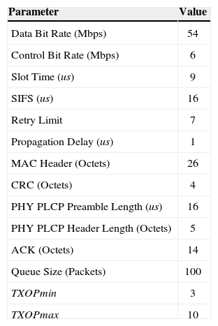
Simulation parameters.
| Parameter | Value |
|---|---|
| Data Bit Rate (Mbps) | 54 |
| Control Bit Rate (Mbps) | 6 |
| Slot Time (us) | 9 |
| SIFS (us) | 16 |
| Retry Limit | 7 |
| Propagation Delay (us) | 1 |
| MAC Header (Octets) | 26 |
| CRC (Octets) | 4 |
| PHY PLCP Preamble Length (us) | 16 |
| PHY PLCP Header Length (Octets) | 5 |
| ACK (Octets) | 14 |
| Queue Size (Packets) | 100 |
| TXOPmin | 3 |
| TXOPmax | 10 |
In order to alleviate the fairness problem, we need to allocate the TXOP limit value of a station based on its delay bound. In this Section, we propose an efficient and dynamic TXOP allocation algorithm to improve the QoS requirement for the stringent real-time constraint of multimedia traffic. The proposed ATA scheme is made up of two processes. First, each station calculates the TXOP limit value (TXOPDB) based on its own delay bound. Second, the QAP measures traffic load and transmits it to each station through a beacon frame. Then, a station calculates the TXOP limit value (TXOPCBR) based on the load. For each station, the TXOP limit value to be actually used to transmit data packets is the sum of TXOPDB and TXOPCBR.
3.1TXOPDB calculation processBefore describing the TXOPDB calculation process, we introduce a new terminology definition. Let us denote a successful transmission interval as the time interval between two consecutive successful transmissions (see Figure 3), which is made up of two components: idle and busy periods. An idle period extends over consecutive empty slots and a busy period corresponds to a successful transmission by other stations or collided transmission, including AIFS or EIFS closing the transmission, respectively.

The successful transmission interval (STI) is updated after a station successfully transmits its own data packet. A station measures the instantaneous successful transmission interval (InsSTI). The proposed scheme maintains an average (MeasuredSTI) of the InsSTI values. Upon obtaining a new InsSTI, the ATA scheme updates MeasuredSTI by exploiting the following moving averaging window:

where, α is a smoothing factor in the range of [0, 1] and generally set to 0.9.
The InsSTI values fluctuate from interval to interval. Therefore, performance fluctuates considerably if the MeasuredSTI is used in TXOP limit calculation. Consequently, it is desirable to set the STI to MeasuredSTI plus some margin. The margin should be large when there is a lot of fluctuation. And it should be small when there is little fluctuation. We use the InsSTI variation (DevSTI) as an estimate of how much InsSTI deviates from MeasuredSTI[13]. It is as follows:

where, β is also a smoothing factor in the range of [0, 1] and its recommended value is 0.75. Note that DevSTI is the difference between InsSTI and MeasuredSTI. After obtaining DevSTI, STI is calculated as follows:

Figure 4 shows the pseudo-coded algorithm for calculating TXOPDB based on the STI. Although TXOP limit value is given as time interval in the IEEE 802.11e standard, here it is represented in terms of the number of data packets.

In the proposed ATA scheme, TXOPDB is allocated between the minimum value (TXOPmin) and the maximum value (TXOPmax). In the algorithm, TXOPDB is initialized to 0 (line 1). For each TXOP limit value, the ATA scheme checks whether all the data packets in the queue meet their delay bounds or not (line 2). The variable isSatisfied in line 3 holds the values TRUE or FALSE. It is initially set to TRUE. If all the data packets meet their delay bounds, it holds TRUE. Otherwise, it is set to FALSE. We check whether or not each data packet meets its own delay bound from 0 to the queue length (Q_Len) in a sequential queue index order (lines 4-9). For a given txop_sz, we need ⌈Q_Len/txop_sz⌉ TXOP limit values to transmit all the data packets in the queue. ⌈x⌉ rounds to the largest integer smaller than or equal to x. The variable txop_ID represents the TXOP limit number to which data packet i belongs (line 5). We use ⌈x⌉ since the TXOP limit number starts from 0. End time of the txop_IDth TXOP limit value is calculated (line 6). And then end time of a packet i’s transmission is calculated (line 7). Here, DATA is the transmission time of a data packet. If the packet i’s end time is larger than its own delay bound, it cannot be transmitted within the bound. Therefore, the parameter isSatisfied is set to FALSE (line 8). Figure 5 shows the example of relation between end time of packet transmission and delay bound. The delay bound of each data packet should be larger than its own transmission end time to be successfully transmitted to a receiver. If the ATA scheme finds a txop_sz for all the data packets, TXOPDB is set to the txop_sz and terminates the for loop (lines 10-13). If there is no txop_sz which meets the delay bounds of all the data packets, the TXOPDB is set to TXOPmax (line 15).
3.2TXOPCBR calculation process
If the TXOP limit value is allocated only based on the delay bound or on the queue length, there is a major drawback. Stations are limited to low data rates even when there are only few stations with packets to send. In this case, network load is so low that the stations can meet their delay bounds. However, the stations need several channel contentions due to small TXOP limit value, and experience long delay. In order to reduce the delay, we allocate additional TXOP limit value to stations when network is not congested. This is used to improve the use of the channel capacity available in networks and provides greater efficiency, by dynamically allocating more TXOP limits to stations.
For TXOPCBR, the QAP measures traffic load (i.e., channel busyness ratio). Channel busyness ratio is calculated by dividing the busy time of channel by a beacon frame transmission period. Busy time means time when channel is used, whether packets are successfully transmitted or not.
The QAP measures channel busy time (Busy) by using the carrier sensing during a beacon frame transmission period. Channel busyness ratio (CBR) is calculated as follows:

where, BeaconPeriod indicates the period of a beacon frame.
As the channel busyness ratio calculated in Eq. 5 fluctuates very irregularly in each calculation, performance fluctuates considerably if the calculated value is used as it is. Moving average window is used as follows:

where, InsCBR is the instantaneous channel busyness ratio. After measuring the ratio, the QAP transmits it to each station through a beacon frame. Then, a station calculates the TXOP limit value (TXOPCBR) based on the information as follows:

In Eq. 7, we use the square of (1-CBR) to fast decrease the allocated TXOP limit value as CBR is getting larger.
Figure 6 shows the example of the allocated TXOPCBR based on CBR when TXOPmax is set to 10. If the channel busyness ratio is close to zero, then there are few stations with data packets to send and it is unlikely that the network is congested. Hence, the TXOPCBR is close to TXOPmax. On the other hand, when the channel busyness ratio is close to 1, the TXOPCBR is set to smaller TXOP limit value. One important aspect of Figure 6 is the fact that as the channel busyness ratio approaches 0, the TXOPCBR increases rapidly. A large percentage increase in the channel busyness ratio results in a much smaller percentage decrease in TXOPCBR.
4Performance evaluation
Let us discuss the simulation results of the proposed ATA scheme. To validate the proposed scheme, we compare them to the results of the TBD scheme.
The parameters used in the simulation are listed in Table 1. We simulated an IEEE 802.11a network with transmission rates of 54Mbps for data packets and of 6Mbps for control packets such as ACK, respectively. A queue size of 100 packets is used. Although TXOP limit value is given as time interval in the IEEE 802.11e standard, here it is represented in terms of the number of data packets. Thus, TXOPmin and TXOPmax values are set to 3 and 10 data packets, respectively. For the TBD scheme, we set the threshold of queue length (THqueue) to 50.
In the simulation, two types of traffic are considered: multimedia and background. Two multimedia stations send data packets to the QAP. They have different delay bounds. To distinguish between them, we call one short station and the other long station. The background traffic is used to observe its effects on multimedia traffic. We assume that all the stations are within the transmission range, and the channel is error free.
The traffic parameters are listed in Table 2. A constant data packet size of 1500 octets is used. We use the negative exponential distribution to get the lengths of the data packet inter-arrival times. The average inter-arrival time of the distribution with arrival rate parameter λ is 1/λ [14]. For background traffic, the average inter-arrival time is set to 10,000 us (λ= 0.0001). Thus, each background station generates data packets at a rate of 1.2Mbps. For multimedia traffic, the arrival rate parameter is 0.0012. Therefore, a multimedia station sends data packets at a rate of 14.4Mbps. The delay bounds for the long and short stations are fixed to 25 ms and 15 ms, respectively.
The main performance metrics of interest are normalized throughput, delivery failure ratio, and average delay. The delivery failure ratio is the number of multimedia data packets discarded due to breaking their delay bounds over the total number of data packets. The average delay is the time between a data packet arrival at the queue of a station and the successful data packet transmission to the QAP, including data packet transmission time.
Figure 7 depicts the effect of the number of background traffic stations on the delivery failure ratio. The ATA and TBD schemes have similar result patterns. The delivery failure ratio gradually increases as the number of background traffic stations gets larger. From the figure, we can see that the proposed scheme always has better performance than the TBD scheme. The TBD scheme allocates the TXOP limit value only based on the queue length to stations so that it makes the possibility of the short station breaking the delay bound. However, the ATA scheme allocates the value by considering the network load as well as the delay bounds of all the data packets in the queue. In the proposed scheme, the long station still has low delivery failure ratio than the short one. When there are packet collisions, the stations experience long delay due to channel contentions. In this case, packets at the long station are still successfully transmitted within their delay bound, but those at the short station are discarded due to breaking their delay bound.

Figure 8 shows the simulation results for normalized throughput. From the figure, we see that the proposed scheme always has better performance than the TBD scheme regardless of the variation of the number of background traffic stations. There is almost no performance difference between the short and long stations when there are few background stations because the network is not congested, and collision probability is low. However, as the number of background traffic stations increases, the difference becomes noticeable. This figure shows that compared with the TBD scheme, the proposed scheme reduces the performance difference between the long and short stations although the long station still has slightly higher performance than the short one. This means that the ATA scheme alleviates the fairness problem.

Figure 9 demonstrates the delay performance. We can see that the delay is kept low when there are no background stations. Average delay of both schemes increases as the number of background traffic stations increases. However, the ATA scheme has a lower delay compared to the TBD scheme. The background stations make collisions with the multimedia stations, resulting in longer delay of multimedia stations. If there are few data packet in the multimedia stations, in the TBD scheme, the TXOP limit value is set to TXOPmin, whereas in the ATA scheme, it varies between TXOPmin and TXOPmax. Therefore, the ATA scheme has bigger TXOP limit value than that of the TBD scheme, and needs smaller channel contentions. Consequently, the proposed scheme can transmit data packets fast.
5Conclusions
Multimedia traffic is very sensitive to delay so that it has to be transmitted to receivers within its delay bound. Otherwise, it is discarded at receivers. Under the environment where stations support multimedia applications with different delay bounds, long delay bound stations have the benefit of good performance. To overcome the limitation, we propose an efficient TXOP allocation scheme. Considering delay bound and network load, the proposed scheme dynamically allocates TXOP limit value. The simulation results show that the proposed scheme alleviates the problem.
This work was partially supported by Defense Acquisition Program Administration and Agency for Defense Development under the contract.