


Cascaded tripping of power lines due to mal-operation of zone 3 distance relays is one of the main causes of many blackouts worldwide. The improved protection technique for zone 3 can help to prevent such mal-operation and, thus, more reliable power systems can be envisaged. This paper presents a novel zone-3 setting scheme based on impedance seen by distance relays in order to calculate zone-3 setting of the relays when faults are simulated on the reach of zone-2 of primary distance relays. The new technique is also enhanced to be used in an adaptive protection system. Since three phase fault rarely occurs in the system and in order to have better demonstration of effectiveness of the proposed scheme, it is tested for various type of faults such as, two phase (AB), single phase to ground (AG) and two phase to ground (ABG) as well as three-phase (ABC) using data simulated through DIgSILENT in the IEEE 30-bus test system during different topologies. The simulation results show that the novel zone 3 distance relay elements using the proposed method operate correctly for various events.
Zone 3 of a distance relay is traditionally used to provide the remote backup protection in case of the failure of the primary protection at the remote substation and is typically set to cover about 120% of the longest adjacent line. Moreover, this zone is given a delay time twice that associated with zone 2 times to achieve time selectivity, and the time delay is typically set in the range of 1–2 s. On account of covering an adjacent line by zone 3, a large infeed from the remote terminal causes the relay to under-reach. Likewise, a large outfeed causes an over-reach. Thus, a very large load at the remote terminal may cause distance relays to mal-operate which, in turn, leads to loss of security due to undesirable zone 3 trip-ping [1-3]. Some approaches like adaptive relaying where proposed for this situation. The concept of adaptation has been introduced to protection relays [4], [5], which has received increasing interest during the last decade due to the advancement of computers, communication systems and software techniques [6], [7]. The benefit of adaptive protective relaying arises from the integration with substation control and data acquisition functions and interfacing with central energy management system [8]. In [9] a new method is presented to increase the second- zone coverage of distance relays without causing over-reaching problems. A novel method to optimize the settings of the resistive and reactive reaches of the zones of the distance relays is represented in [10]. The method considers the probabilistic behavior of the variables that affect the apparent impedance seen by relays: pre-fault load flow, fault type, faulted line, distance up to the fault, fault resistance, and measurement errors. A new algorithm based on two new criteria: 1) the maximum value of the transient monitoring function obtained from three-phase currents and 2) the phase angle of the positive-sequence impedance is addressed in [11] to support zone 3 of the distance relay. The equivalent expression of the operation margin expressed by a function of bus voltage is established, and a preventive control model based on the sensitivities of the operation margin to power injection is proposed in [12] to overcome the overreaching property of zone 3 impedance relays (mho relays). A zone-3 revisited to re-examine the application of zone 3, to describe situations where it can be properly utilized, where it can be removed without reducing the reliability of the system protection and, if used, to explore the ways it can be set, is presented in [13]. Zone-1 reach settings for transmission line distance relays to prevent overreach resulting from coupling capacitor voltage transformer (CCVT) transients is studied on [14]. This scheme focuses on digital distance relays and determining appropriate relay reach settings to account for the effects of CCVT transients during faults for CCVTs with active ferro-resonant suppression circuits. A new algorithm for adaptive setting of Zone 3 of distance relays during severe voltage fluctuations is proposed in [15]. The developed algorithm is based on dynamic adjustment of zone 3 setting of distance relays to avoid mal-operation. An adaptive first-zone distance protection scheme for line with fixed series compensation connected at one end using local measurements is proposed in [16]. Impedance offered by series capacitor in this technique is estimated using relay end fault current. The integration of the series capacitor (SC) into the transmission line makes the coordination problem more complex. The under-reaching and over-reaching of distance protection for transmission line is more severe with SVC at mid-point of the transmission line [17]. In order to mitigate the mal-operation of the distance protection, the adaptive scheme is presented based on recursive simulation study. A method based on calculating voltage across faulted open port and faulted electric parameters is proposed in [18] to improve calculation accuracy of relay setting and coordination. A new algorithm is proposed in [19] that utilizes Synchronized Phasor Measurements (SPM) to enhance the operation of distance protection zone 3 in many aspects such as distinguishing between actual system faults and load encroachment and not affecting the tripping decision by the value of fault resistances as well. A synchrophasor data-based technique for correct zone 3 operations is accomplished in [20] using impedances calculated from voltage and current signals from synchrophasors placed at strategic locations. In order to significantly change with the operating conditions, an adaptive zone 2 distance relay characteristics for multi-terminal power transmission system using PMU data is proposed in [21] in which the apparent impedance equation includes infeed, outfeed and line shunt capacitance of the multi-terminal system. Ref. [22] proposes an algorithm based on the detection of remote breaker operation following zone 2 fault detection by local distance relay and it uses as a basis the monitoring of changes on a proposed signal. Proposed algorithm allows the trip acceleration on zone 2 of non-communicated distance relays for cases where faults are located inside the protected line. The conventional methods of distance relay coordination usually disregard the effect of the fault current in-feed at the remote buses. This impact causes the impedance presented to the relay to be much greater than the actual impedance and leads to the under-reach of the relays. This problem is more effective in the zone-3 setting of the distance relay and makes this zone be identified as one of the contributing causes of blackouts. Hence, determining the accurate zone-3 setting of the distance relay is an important issue. This paper proposes a new technique for determining settings of zone-3 distance relays. The proposed technique uses impedance seen by distance relays to calculate zone-3 setting of the relays when faults are simulated on the reach of zone-2 of primary relays. Results show that better backup protection and higher line coverage are provided using both adaptive and non-adaptive versions of the proposed technique. The adaptive version of the proposed method is utilized under normal circumstances, but during failures, such as communication failures its non-adaptive version is activated.
2Zone-3 reach setting2.1Conventional methodTwo different scenarios can be considered due to its significance for the third zone setting of a distance relay. According to Figure 1, these scenarios are as follows:

Scenario 1. The longest line emanating from the remote bus B should be seen by the third-zone relay located near the local bus A (RAB):
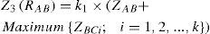
Where Z3(RAB) is the impedance setting for the third zone of the relay RAB; k1 is a safety margin within the range of 1.1 to 1.2; ZAB is the positive sequence impedance of the protected line A-B and ZBCi is the positive sequence impedance of the next line B-Ci. In this scenario, Z3(RAB) may overlap that of similar relays on the shorter lines emanating from the remote bus, i.e. Z3(RBCj) where B-Cj is a line emanating from the bus B with a rather small length. Therefore, the time delay of the third-zone of RAB should be properly increased.
Scenario 2. The third-zone reach should be as large as possible, but it never overlaps that of similar relays on the lines emanating from the remote bus B. Eq. 2 fulfils the second scenario:
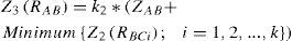
Where k2 is a safety margin within the range of 0.8 to 0.9 and Z2(RBCi) is the second-zone reach of relay RBCi (i=1, 2, …, k), which is usually calculated as follows:
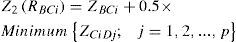
Where ZCiDj is the positive sequence impedance of the far line Ci-Dj (j=1, 2, …, q) and q is the total number of buses connected to the far bus Ci. The second scenario is selected and used in this paper with k2=0.85.
Considering Figure 2, which is a portion of the IEEE 30-bus test system, the second Scenario is applied for the third-zone setting of relay R74 as follows. Zone-2 impedance setting of relays R72 is first calculated using (3) and then replaced in (2) to achieve the required zone-3 setting. It yields zone-3 impedance setting of 112<4050° Ω for R74.

On interconnected power systems, the effect of fault current in-feed at the remote bus would cause the impedance presented to the relay to be much greater than the actual impedance to the fault and this needs to be taken into account in setting the third-zone each. The main drawback of the conventional technique is that it ignores such in- feed currents.
2.2Proposed methodThe proposed technique uses short-circuit study method to determine the apparent impedance seen by the zone-3 relay (ZAF) when faults are on the lines emanating from the far buses (i.e. buses Ci in Figure 1 for relay RAB) including in-feed current effects;
Corresponding zone-3 reach is then calculated using ZAF. The required zone-3 reaches are computed for all network topologies considering single-level contingencies and for maximum and minimum outputs of generation sources. The least zone-3 reach computed in these outlines is selected as the final settable zone-3 reach of the relay. This procedure increases the reach of the zone-3 relays without any impedance via the operation of the related primary relays.
Consider again the sample transmission system shown in Figure 1; the proposed technique uses the following steps for computing the zone-3 reach of the relay RAB:
- 1)
- 2)
Remove the line Ci-Dj from the system.
- 3)
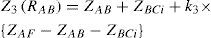
As indicated in Figure 3, simulate a fault (ABC, AB, ABG or AG) at the end of zone-2 reach of relay RBCi within the line CiDjj (jj≠j) when its remote end breaker is open, determine ZAF and then, compute zone-3 impedance reach as follows:
Where k3 is a safety margin lower than 1 (0.9 in this paper) to ensure non-overlap between Z3(RAB) and Z3(RBCi)
- 4)
Repeat step 3 for faults at the end of zone-2 reach of relay RBCi within the other lines emanating from bus Ci.
- 5)
Return the removed line Ci-Dj back into service.
- 6)
Repeat steps 2 to 5 for the remaining lines or other elements (transformers, generators, etc.) connected to bus Ci being taken out of service (removing one line or element at a time).
- 7)
Repeat steps 2 to 6 for all buses Ci; i=1, 2, …, k.
- 8)
Remove the line B-Ci from the system.
- 9)
Simulate a fault (ABC, AB, ABG or AG) at the ends of zone-2 reach of relays RBCii (ii=1, 2, …, k and ii≠i) in turn, with the remote end breaker of the faulty line being open, determine ZAF and compute zone-3 impedance reach using (4) for each case.
- 10)
Repeat step 8 for all lines or elements connected to bus B and then repeat step 9.
- 11)
Simulate a fault (ABC, AB, ABG or AG) at the ends of zone-2 reach of relays RBCi (i=1, 2, …, k) in turn, when all the lines and elements are in service and all breakers are closed, determine ZAF and compute zone-3 impedance reach using (4) for each case.
- 12)
Select the least zone-3 impedance reach calculated in steps 1 to 11.
- 13)
If the least zone-3 impedance has been obtained in the step 11, then go to step 16, otherwise continue with the following step.
- 14)
Identify the line or element that the least zone-3 impedance (in step 12) has been reached by removing it out of service; remove it again while all the circuit breakers are closed. Then, Simulate a fault (ABC, AB, ABG or AG) at the ends of the zone-2 relays RBCi in turn, determine ZAF and compute zone-3 impedance reach using (4) for each case.
- 15)
Compare the least zone-3 impedance reach obtained in the step 14 to that obtained in the step 12 and replace the lower one as the least zone-3 impedance reach.
- 16)
Repeat steps 1 to 15 for minimum outputs of generation sources.
- 17)
Set the smallest zone-3 impedance obtained through the steps 1 to 16 as the final setting for the zone-3 impedance reach of the relay RAB.
- 18)
Repeat steps 1 to 17 to determine zone-3 setting of the remaining relays in the system.

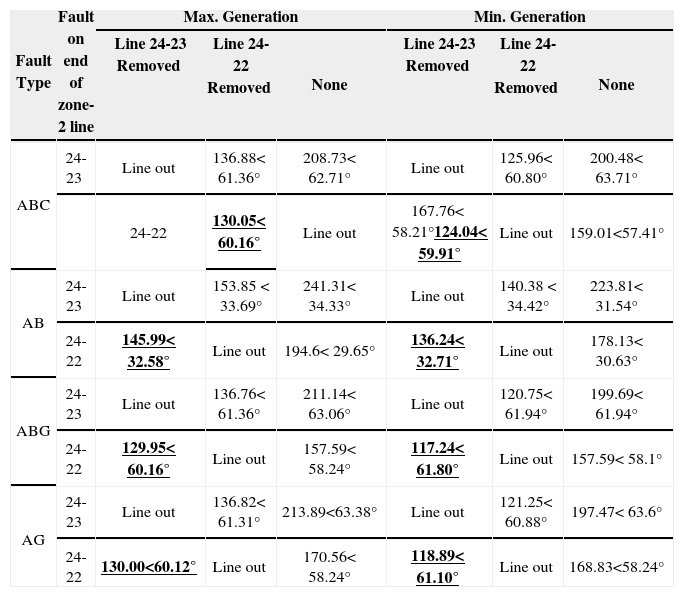
The proposed technique is tested on the system depicted in Figure 2 for zone-3 impedance reach setting of relay R74. The resultant zone-3 impedance reaches are tabulated in Table 1 and 2.
Possible zone-3 setting calculated for relay R74 on maximum and minimum generation for various faults.
| Fault Type | Fault on end of zone-2 line | Max. Generation | Min. Generation | ||||
|---|---|---|---|---|---|---|---|
| Line 24-23 Removed | Line 24-22 Removed | None | Line 24-23 Removed | Line 24-22 Removed | None | ||
| ABC | 24-23 | Line out | 136.88<61.36° | 208.73<62.71° | Line out | 125.96<60.80° | 200.48<63.71° |
| 24-22 | 130.05<60.16° | Line out | 167.76<58.21°124.04<59.91° | Line out | 159.01<57.41° | ||
| AB | 24-23 | Line out | 153.85 <33.69° | 241.31<34.33° | Line out | 140.38 <34.42° | 223.81<31.54° |
| 24-22 | 145.99<32.58° | Line out | 194.6<29.65° | 136.24<32.71° | Line out | 178.13<30.63° | |
| ABG | 24-23 | Line out | 136.76<61.36° | 211.14<63.06° | Line out | 120.75<61.94° | 199.69<61.94° |
| 24-22 | 129.95<60.16° | Line out | 157.59<58.24° | 117.24<61.80° | Line out | 157.59<58.1° | |
| AG | 24-23 | Line out | 136.82<61.31° | 213.89<63.38° | Line out | 121.25<60.88° | 197.47<63.6° |
| 24-22 | 130.00<60.12° | Line out | 170.56<58.24° | 118.89<61.10° | Line out | 168.83<58.24° | |
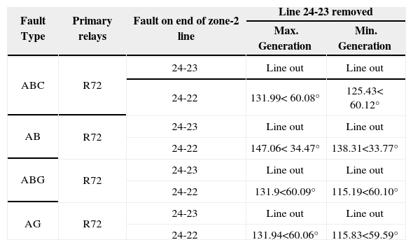
Fault impedance seen by relay R74 with fault at the end of zone-2 of each line for various faults.
| Fault Type | Primary relays | Fault on end of zone-2 line | Line 24-23 removed | |
|---|---|---|---|---|
| Max. Generation | Min. Generation | |||
| ABC | R72 | 24-23 | Line out | Line out |
| 24-22 | 131.99<60.08° | 125.43<60.12° | ||
| AB | R72 | 24-23 | Line out | Line out |
| 24-22 | 147.06<34.47° | 138.31<33.77° | ||
| ABG | R72 | 24-23 | Line out | Line out |
| 24-22 | 131.9<60.09° | 115.19<60.10° | ||
| AG | R72 | 24-23 | Line out | Line out |
| 24-22 | 131.94<60.06° | 115.83<59.59° | ||
As seen, the smallest zone-3 impedance is obtained (for all type of faults) when line 24-23 is removed and fault occurs at the zone-2 reach of relay R72 on line connecting buses 24 and 22 for both minimum and maximum generation output cases. The smallest zone-3 impedance between min and max generation output will be chosen as final impedance setting for relay R74. Therefore, 124.04<59.91°, 136.24<32.71°, 117.24<61.80°, 118.89<61.10° are respectively selected as final impedance in case of three phase (ABC), two phase (AB), two phase to ground (ABG) and single phase to ground (AG) faults.
2.3DiscussionFigure 4 shows the covered percentage of the far lines (by the new zone-3 setting of relay R74 (Figure 2) in the case where the system generation is at the maximum generation level for different topology.

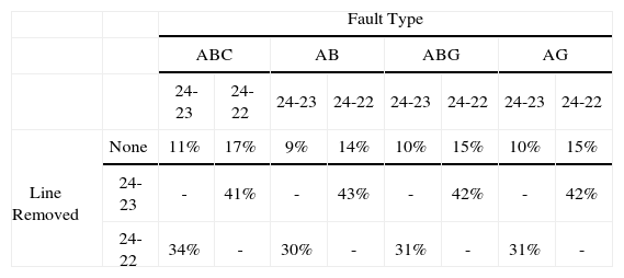
Similar results can be delivered for the minimum level of generation. Tables 3 shows the covered percentage of the far lines by the new zone-3 reach of relay R74 in the case different lines are out of service. An important point here is that when the zone-3 relay is set by the conventional method, no part of the far lines emanating from the far buses is covered by the zone-3 reach due to the in-feed currents effects (that is why it is not shown in Figure 4 and Table 3 as well), thus, the zone-3 relay cannot be a perfect backup protection for the next lines. The new setting method has resolved this problem, while it prevents the zone-3 of the backup distance relay from overlapping with the zone-3 of the next primary distance relays. The same results are obtained for other relays whose zone-3 settings were established using the proposed technique.
Percentage of far line covered by relay R74 for ABC fault when the level of generation is minimum and different lines are out of service through different faults.
| Fault Type | |||||||||
| ABC | AB | ABG | AG | ||||||
| 24-23 | 24-22 | 24-23 | 24-22 | 24-23 | 24-22 | 24-23 | 24-22 | ||
| Line Removed | None | 11% | 17% | 9% | 14% | 10% | 15% | 10% | 15% |
| 24-23 | - | 41% | - | 43% | - | 42% | - | 42% | |
| 24-22 | 34% | - | 30% | - | 31% | - | 31% | - | |
Knowing the power system current topology and the generation level, an adaptive version can be introduced for the proposed zone-3 setting scheme. The adaptive version is principally alike to the non- adaptive scheme apart from the fact that there is no need to compute impedances for the maximum and minimum levels of generation and no contingencies need to be supposed. The apparent impedances and zone-3 reaches are computed for the existent states. The adaptive setting scheme for zone-3 distance relays is reported with supposing the system of Figures 1 and includes the underside steps for determining the zone-3 setting of the relay RAB.
- 1)
Acquire the present operating state of the power system (i.e. topology, power flow, and generation).
- 2)
Simulate a fault (ABC, AB, ABG or AG) at the end of zone-2 reach of relay RBCi within the line CiDj when its far end breaker is open, determine ZAF and compute zone-3 impedance reach of relay RAB by using ZAF and Eq. 3.
- 3)
Repeat step 2 for faults at end of zone-2 reach of relay RBCi on all far lines i.e. lines CiDj for j=1, 2, …, p (fault at one line at a time).
- 4)
Repeat steps 2 to 3 for all zone-2 distance relays RBCI, i=1, 2, …, k.
- 5)
Simulate a fault (ABC, AB, ABG or AG) at the ends of the zone-2 distance relays of the next lines (RBCi, i=1, 2, …, k) when all circuit breakers are closed. Determine ZAF and compute zone-3 impedance reach of relay RAB by using ZAF and Eq. 4.
- 6)
Set the smallest zone-3 impedance obtained through the steps 2 to 5 as the final setting for the zone-3 distance relay RAB.
- 7)
Repeat steps 1 to 6 to determine zone-3 setting of the remaining relays in the system.
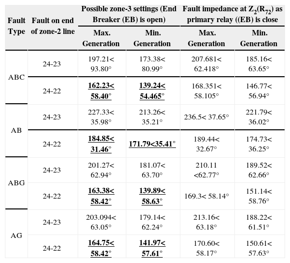
The adaptive version of the proposed scheme is applied to determine zone-3 setting of relay R74 in the system depicted in Figure 2. In this instance, both maximum and minimum generations are considered as distinct operating circumstance of the power system. The possible zone-3 impedance reaches of the relay when three-phase fault occurs at the end of zone-2 (Z2(R72)) reach of the next primary relay on the far lines are tabulated in Table 4.
Possible adaptive zone-3 setting for relay R74 on maximum and minimum generation and different faults.
| Fault Type | Fault on end of zone-2 line | Possible zone-3 settings (End Breaker (EB) is open) | Fault impedance at Z2(R72) as primary relay ((EB) is close | ||
|---|---|---|---|---|---|
| Max. Generation | Min. Generation | Max. Generation | Min. Generation | ||
| ABC | 24-23 | 197.21<93.80° | 173.38<80.99° | 207.681<62.418° | 185.16<63.65° |
| 24-22 | 162.23<58.40° | 139.24<54.465° | 168.351<58.105° | 146.77<56.94° | |
| AB | 24-23 | 227.33<35.98° | 213.26<35.21° | 236.5<37.65° | 221.79<36.02° |
| 24-22 | 184.85<31.46° | 171.79<35.41° | 189.44<32.67° | 174.73<36.25° | |
| ABG | 24-23 | 201.27<62.94° | 181.07<63.70° | 210.11<62.77° | 189.52<62.66° |
| 24-22 | 163.38<58.42° | 139.89<58.63° | 169.3<58.14° | 151.14<58.76° | |
| AG | 24-23 | 203.094<63.05° | 179.14<62.24° | 213.16<63.18° | 188.22<61.51° |
| 24-22 | 164.75<58.42° | 141.97<57.61° | 170.60<58.17° | 150.61<57.63° | |
As seen the smallest calculated zone-3 impedance for the maximum and minimum generations in case of ABC, AB, ABG and AG faults are respectively 162.2385 <58.4035°, 139.24 <54.465°; 184.8527<31.4629°, 171.7902<35.4175°; 163.3826 <58.4264°, 139.8956<58.6378° and 164.7506 <58.4248°, 141.974 <57.6118° Ω respectively. These impedances are selected as final impedance setting for the zone-3 of distance relay R74 under related operating circumstances of the power system. Figure 5 depicts that the adaptive version of proposed technique for determining zone-3 impedance settings provides more coverage of the far lines than the non- adaptive version.
4Case study
The implementation and more evaluation of the adaptive and non-adaptive versions of the proposed method so as to determine zone-3 setting of distance relays protecting the transmission lines of a test power system is demonstrated in this section. The transmission system under study is the 30-bus IEEE test system as illustrated in Figure 6 and consists of 43 transmission lines (86 distance relays) operating at 138kV levels. The technical information of the network is given in [23]. Zone-3 settings determined by the non-adaptive version of the proposed (PNA) method can be saved on relays as a setting group.

This setting group will be activated in the instance of adaptive setting system failure for example due to communications failure. Numerous scenarios of the power system are investigated in order to set and examine the coverage supplied by zone-3 of distance relays. The next and far lines coverage supplied by proposed technique is compared with the conventional setting techniques and some results are drawn here. Table 5 compares the zone- 3 reach settings of some distance relays obtained using conventional and proposed methods for the maximum generation condition.
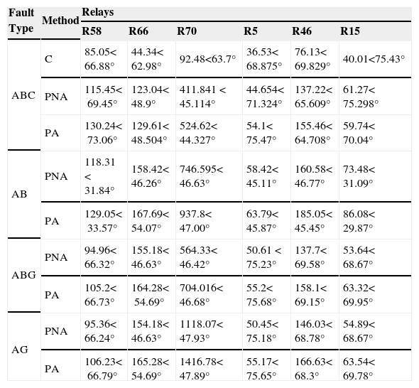
Possible zone-3 setting for different relays in terms of various faults and maximum generation condition.
| Fault Type | Method | Relays | |||||
|---|---|---|---|---|---|---|---|
| R58 | R66 | R70 | R5 | R46 | R15 | ||
| ABC | C | 85.05<66.88° | 44.34<62.98° | 92.48<63.7° | 36.53<68.875° | 76.13<69.829° | 40.01<75.43° |
| PNA | 115.45<69.45° | 123.04<48.9° | 411.841 <45.114° | 44.654<71.324° | 137.22<65.609° | 61.27<75.298° | |
| PA | 130.24<73.06° | 129.61<48.504° | 524.62<44.327° | 54.1<75.47° | 155.46<64.708° | 59.74<70.04° | |
| AB | PNA | 118.31 <31.84° | 158.42<46.26° | 746.595<46.63° | 58.42<45.11° | 160.58<46.77° | 73.48<31.09° |
| PA | 129.05<33.57° | 167.69<54.07° | 937.8<47.00° | 63.79<45.87° | 185.05<45.45° | 86.08<29.87° | |
| ABG | PNA | 94.96<66.32° | 155.18<46.63° | 564.33<46.42° | 50.61 <75.23° | 137.7<69.58° | 53.64<68.67° |
| PA | 105.2<66.73° | 164.28<54.69° | 704.016<46.68° | 55.2<75.68° | 158.1<69.15° | 63.32<69.95° | |
| AG | PNA | 95.36<66.24° | 154.18<46.63° | 1118.07<47.93° | 50.45<75.18° | 146.03<68.78° | 54.89<68.67° |
| PA | 106.23<66.79° | 165.28<54.69° | 1416.78<47.89° | 55.17<75.65° | 166.63<68.3° | 63.54<69.78° | |
As seen, a higher zone-3 impedance setting can be achieved using the proposed method (PM) compared with the conventional (C) method for all the relays. For example in terms of ABC fault, the possible setting for relay R46 via the conventional method is 76.1373<69.829° Ω while this value is 137.224<65.609° and 155.46<64.708° Ω via non-adaptive (PNA) and adaptive version (PA) of the proposed method, respectively. The results divulge significant increase in the impedance setting for the relay. The same result can be derived from other type of fault for all relays. As previous cases in the section 3, the zone-3 relays set by the conventional method have no coverage of the far lines due to in-feed currents. Not only does the proposed technique cover remote lines, but also it covers significant percentage of far lines emanating from the far buses without any coordination problems. Figure 7 depicts this fact.

As can be seen from the figure, the better coverage is provided by the adaptive version for all relays. For example, 19% of the line connected between buses 12 and 15 can be covered by zone-3 relay R58 using non-adaptive (PNA) version of the proposed method whereas this valueis increased to 38% using the adaptive version (PA). The same consequences can be acquired of other relays in terms of different faults and operating conditions (minimum generation).
5ConclusionOne of the most noticeable protective relay characteristic may be the undesired operation of the third zone of DRs on account of the incorrect zone 3 relay operations which is contributive to the severity of blackouts. In this regard, the accurate zone 3 setting is supposed to be unavoidable. This main contribution of this study is to develop a new scheme for calculating zone-3 setting of DRs. The proposed method employs impedance seen by DRs to calculate zone-3 setting when faults are simulated on the reach of zone-2 of primary DRs. The proposed method and its adaptive version are tested in the IEEE 30-bus system through different conditions including various types of faults (ABC, AB, ABG and AG) and the maximum and minimum generation outputs of the power system to indicate its remarkable efficiency and adaptivity with the operating conditions. Simulation results divulge the ability of the proposed technique to significantly increase the reach of zone-3 relays and better line coverage compared to conventional technique without causing mis-coordination problems. The core advantages of having longer zone 3 reach consist of better backup protection for primary relays, increasing security of the power system, covering all the lines emanating from far buses and mitigating mis-coordination problems between primary and backup relays.