


We describe a method to compute the Euler number of a binary digital image based on a codification of contour pixels of the image’s shapes. The overall procedure evolves from a set of lemmas and theorems, their demonstration and their numerical validation. The method is supported through an experimental set which analyzes some digital images and their outcome to demonstrate the applicability of the procedure. The paper also includes a discussion about present and futures steps on this research.
Se describe un método para el cálculo del número de Euler de una imagen digital binaria basado en una codificación del contorno de las formas en la imagen. El procedimiento tiene su base en un conjunto de lemas y teoremas, su demostración y su validación numérica. El método se soporta a través de una experimentación que analiza varias imágenes digitales para demostrar la aplicabilidad del procedimiento. El artículo incluye también una discusión acerca de pasos presentes y futuros de investigación.
Shape classification is one of the main problems in pattern recognition. In the particular case of bidimensional shapes, many methods have been developed. The interested reader may refer, for example, to [25].
A digital binary image is a two-dimensional array that has been obtained from a gray-level image that has been discretized at two levels, say 0 and 1. An image like this is composed of all the flat connected regions representing projections of perceived objects onto the discrete plan. The elements or cells that compose the regions are labeled with level 1, whereas the background is labeled with level 0. From the projected region of each observed object several describing geometric and topological features can be computed. The Euler number is one of these features.
Mathematically, the Euler number of a binary image is defined as

where N is the number of regions of the image (number of connected components of the object) and H is the number of holes in the image (isolated regions of the image’s background).
1.1Applications of the Euler numberThe Euler number has been successfully applied for image analysis and visual inspection over binary images, as reported in [23].
In [2], the Euler number has been used to automatically recognize the numbers and characters in Malaysian car license plates.
In [18], the so-called fast Euler numbers are applied to automatically threshold a binary image. The proposal computes Euler numbers in just one single image raster scan.
In [20], Euler numbers have been employed to analyze textural and topological features of benchmark images. Likewise, the same feature has been used to describe structural defects upon binary images that have been affected by noise in [26]. In short, the Euler characteristic has also been used to extract lung regions from gray-level chest X-ray images in [21].
1.2Implementations and patentsSeveral implementations to speed up the computation of the Euler number to make it useful in real time applications have been reported in literature, even related patents have been found.
In [12], for example, a fast algorithm for computing the Euler number of an image and its VLSI implementation is presented. Likewise, novel pipeline architecture is comprehensively described in [7]. The on-chip computation of a binary image Euler number with applications to efficient database searching is presented in [6].
A modification to the algorithm presented in [18], in order to allocate its execution over a Field Programmable Gate Array with a pipelined architecture is described in [3].
Finally, one of the first patents about the Euler number computation for binary images is described by Acharya et al. in [1].
1.3MethodsSeveral methods to compute the Euler number of a binary image have been reported in literature. For instance, the Euler characteristic is obtained by means of a quad-tree representation of the image under scrutiny [14]. In [17], linear quad-trees are used to perform the same task, whereas in [5] a bin-tree representation is employed. In [4], the Euler number is considered as the value of a certain additive functional which belongs to the so-called Quermass-integrals family.
The Euler number can be also defined in term of vertices, basic square faces and edges from the binary image squared-graph [10]. The so-called connectivity image graph has been analyzed in [9], whereas an integral geometric approach is studied in [13] with a full proof about the Euler number equation in [22]. In [11], the Euler number is computed by means of the so-called connectivity image graph. In [16] an integral geometric approach for the Euler feature is computed upon spatial images. In [27], the authors use the notion of the algebraic topology complex to compute the Euler number of a given object. In [24], mathematical morphology operations and the additive property of this feature are adopted to calculate Euler number of binary objects.
The Euler characteristic of discrete objects and discrete quasi-objects is computed in [15a] in terms of the so-called vertex angles of the discrete surfaces. These vertex angles are defined in terms of the curvature indices of the discrete contour of a discrete object. The authors prove the relation between the number of point indices, the numbers of holes, genus, and cavities of an object. This is the angular Euler characteristic of a discrete object.
In [15b] the number connected components (first planar Betti number) and the number of holes (second planar Betti number) are estimated by approximating the digital image by polygonal sets derived from its digitalization. As stipulated by Equation (1) the estimation of the Euler number of the shape is given by the difference of these two Betti number estimators.
In [16a] the Euler characteristics of a digital image composed of k connected shapes are computed in terms of the so-called Morse operators. Morse operators form a powerful topological tool to handle object classification. Both the 4 and 8 connected cases are considered in this reference.
The study in [13] presents the Euler number computation for binary images in terms of the number of terminal points, that is, number holding only one neighbor and the number of three-edge points, that is, points which have been linked to three neighboring others over skeleton regions within the image.
The contact perimeter for “unit-with” shapes is used in [9] to compute the Euler number. Two variants of such proposal for the case of region-based shapes are described in [19a] and [19] for the cases of shapes composed of square and hexagonal cells, respectively.
1.4Contribution of the paperIn this paper, the Euler number of an object is computed in terms of the number of cell faces that each shape’s contour corner touches at that position. Results in the case of objects composed of square and hexagonal cells are given. The method is supported through an experimental set which analyzes some digital images and their outcomes to demonstrate the applicability of the procedure. Also, the set of formal propositions that support the operation of the proposed method are both demonstrated and numerically validated.
1.5Organization of the paperThe paper is organized as follows: Section 2 is devoted to provide basic concepts and required definitions. Sections 3 and 4 develop key material on the paper as the fundamental propositions supporting the methodology. All the propositions are demonstrated and numerically validated. In Section 5 we give a unifying corollary that integrates the main results introduced in Sections 3 and 4. In Section 6 we develop several examples considering several digital binary images showing to verify the robustness of the proposal. Finally, Section 7 discusses some conclusions and future directions for research work.
2Basic definitionsIn this section we present the definitions and basic results that will allow us to derive the method to compute the Euler number of a binary shape. Only the case of shapes composed of square cells will be touched in this section. The corresponding results related to shapes composed of hexagonal will be provided in Section 4.
Definition 1A binary shape Sn is a k-connected region composed of n square cells. In the case of square cells, Sn eight-connected can be four-connected or eight-connected.
As is known when using pixels to represent shapes, a structural problem called connectivity paradox appears. As already mentioned, there are two ways of connecting pixels: four connectivity and eight connectivity. In the content of this paper, four connectivity is considered. In other words, if p and q are any two pixels belonging to shape Sn, then p and q will appear connected by one of their sides.
Definition 2Let a shape Sn with p being one of its cells and p representing one contour element having at least one neighbor pixel belonging to the shape’s background.
In this paper, both shape classes are considered: those including holes and those with no holes at all. Therefore the shape’s contour is built by the bounding contour plus the bounding hole contours, if they are actually present.
According to [8], each exterior corner of a contour cell (when it is in direct contact with the shape’s background) can be coded by the number of cell vertices it touches at that position. Considering such a fact, Figure 1(a) presents a discrete shape composed of 17 pixels. Figure 1(b) shows the numbered corners of the shape presented in Figure 1(a). As it is shown by Figure 1(b), there are only three different numbers of cell vertices for the bounding contour: 1, 2 and 3. In this paper, such a corner code can be denoted as variable VC.
 A Shape Composed Of 17 Pixels. (b) The Shape and Corner Codes of its Contour Corners. (c) The Shape and Corner Codes of its Contour Corners When a Hole is Added to the Shape. (d) The Shape With the Corner Codes of its Contour Corners When a Pixel is Four Connected to the Shape.")
(a) A Shape Composed Of 17 Pixels. (b) The Shape and Corner Codes of its Contour Corners. (c) The Shape and Corner Codes of its Contour Corners When a Hole is Added to the Shape. (d) The Shape With the Corner Codes of its Contour Corners When a Pixel is Four Connected to the Shape.
Let Snc represent the set of contour cells of a shape Sn. Let N1 be the number of vertices of Snc for which VC=1, and let N3 be the number of vertices of Snc for which VC=3.
For example, considering the shape in Figure 1(b), N1=9 and N3=5.
Now, for a given shape, numbers N1 and N3, change by deleting or by adding cells to the shape. Considering the shape of Figure 1(a), in case one interior pixel is extracted following Figure 1(c), a hole would emerge with N3=9. If the corresponding pixel is added to the same shape as shown by Figure 1(d), N1=8 and N3=4.
Lemma 1Adding a hole to one shape composed of square cells is done as follows:
- a)
By deleting interior pixels of the shape. In this case note thatN3 is increased by 4, each time a pixel is deleted, whereasN1 remains unchanged. Refer to Figure 2(a).
- b)
By adding as many exterior cells in such a way that a hole is formed. In this case note thatN3 is increased by 2, whereasN1 is decreased by 2, refer to Figure 2(b).
 Deleting a Pixel, First Case. (b) Adding a Pixel, Second Case.")
In this section, numbers N1 and N3 are used to derive two topological features of a binary shape: its number of holes and its Euler number. Only the case of shapes composed of square cells is faced in this section. Results concerning shapes composed of hexagonal and triangular cells will be given in Section 4.
Theorem 1Let N1 be the number of N1 and N3 be the number of N3 which are added to the interest shape. The number of added holes is always equal to
Proof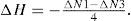
Following Lemma 1, a hole is generated when N1−N3=−4. If H holes are generated, then

To numerically validate Theorem 1, let us use the shapes of Figures 3(a) and 3(c). As we can see, both shapes have no holes. For the first one: N1=7 and N3=3, whereas for the second shape: N1=8 and N3=4. Now, if we add holes to these shapes (one hole to the first shape and two holes to the second shape) as stated by Lemma 1, we have the images shown in Figures 3(b) and 3(d). In both cases, according to Theorem 1, we should have that H=1 for the first shape and H=2 for the second shape. Let us verify this. For the shape of Figure 3(3b): N1=0 and N3=4, and ΔH=-ΔN1-ΔN34=-0-44=1, as expected. For the shape of Figure 3(d): N1=0 and N3=8 and ΔH=-ΔN1-ΔN34=-0-84=2. This numerically validates Theorem 1.
Theorem 2(a).")
The number of holes H of a binary shape is always given as follows:
Proof
By construction, beginning from a minimal shape, such shape is thus composed by one pixel, then: N1i-N3i4=1, where suffix i means initial. Now if a pixel is chosen as to append to such initial shape, it is easy to verify that: N1-N34=1. By continuously adding pixels, a hole will be eventually generated. Following Theorem 1, it yields:

However, N1=N1i+N1 and N3=N3i+N3, then

To numerically validate Theorem 2(a), let us use the shapes of Figures 3(b) and 3(d). As we can see, the first shape has one hole, whereas the second one has two holes. Let us verify this by applying Theorem 2(a). For the first shape: N1=7 and N3=7 and H=-7-74+1=1. For the second shape: N1=7 and N3=11 and H=-7-114+1=1+1=2. This numerically validates Theorem 2(a).
Theorem 2(b)The number of holes E of n binary shapes is always given as follows:
Proof
Starting from n minimal shapes, then N1i-N3i4=n. when adding N1 and N3 we have:

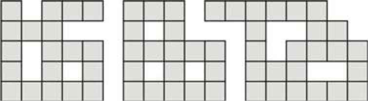
To numerically validate Theorem 2(b), let us use the set of three shapes shown in Figure 4. As we can see, the total number of holes is seven. Let us verify this by applying Theorem 2(b). From Figure 4 we can easily verify that thatN1=21 and N3=37 and H=-21-374+3=7. This numerically validates Theorem 2(b).
.")
At this moment we can derive the main result concerning the computation of the Euler number of a shape or a set of shapes composed of square cells. For this, we use the number of holes of a shape.
Theorem 3The Euler number E of n binary shapes is always given as follows:
Proof
From Equation (1) and by Theorem 2(b)

To numerically validate Theorem 3, let us use again the set of three shapes shown in Figure 4. As we can see, the Euler number for this set of shapes is -4. Let us verify this by applying Theorem 3. We have seen that N1=21 and N3=37 and E=21-374=-4. This numerically validates Theorem 3.
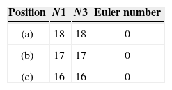
Notice that numbers N1 and N3, the overall number of holes and the Euler number depend solely on the shape’s topology. In other words, the shape’s geometry is irrelevant as long as its topology remains unchanged. For instance, consider the example portrayed in Figure 5 and Table 1 which shows how this fact could be used for shape differentiation.
4Results related to regions composed of hexagonal cells
In this section we present the main results that support the computing of the Euler number of regions composed of hexagonal cells. In all cases we formally demonstrate and numerically validate the propositions.
Following Figure 6, it can be seen that there are only two different kinds of cell vertices for the bounding contour: 1 and 2. Notice that in this case, cells do not present the problem of being connected by their corners. For T=6, cells always will appear connected by their sides to other cells. Now, if N1 and N2 are, respectively, the number of cells touched by a contour vertex, then we have

Adding a hole to one shape composed of hexagonal cells is done as follows:
- a)
By deleting interior cells of the shape. In this case note thatN2 is increased by each time a cell is deleted, whereasN1 remains unchanged. Refer to Figure 7(a).
- b)
By adding as many exterior cells in such a way that a hole is formed. In this case note thatN2 is increased by 4, whereasN1 is decreased by 2, refer to Figure 7(b). We can have also thatN2 is increased by 3, whereasN1 is decreased by 3, refer to Figure 7(c).
 Deleting a Pixel, First Case. (b)-(c) Adding a Pixel, Second and Third Cases.")
Let N1 be the number of N1 and N2 be the number of N2 which are added to the interest shape composed of hexagonal cells. The number of added holes is always equal to
Proof
Following Lemma 2, a hole is generated when N1−N2=−6. If H holes are generated, then

To numerically validate Theorem 4, let us consider the shapes of Figures 8(a) and 8(c). As we can see, both shapes have no holes. For the first shape: N1=14 and N2=8, whereas for the second shape: N1=21 and N2=15. Now, if we add one hole to both shapes as stated by Lemma 2, we have the images shown in Figures 8(b) and 8(d). In both cases, according to Theorem 4 we should have that AH=1 for both shapes. Let us verify this. For the shape of Figure 8(b): N1=0 and N2=6, and ΔH=-ΔN1-ΔN26=-0-66=1, as expected. For the shape of Figure 8(d): N1=−3 and N2=3 and ΔH=-ΔN1-ΔN26=--3-36=1. This numerically validates Theorem 4.
Theorem 5(a)
The number of holes H of a binary shape composed of hexagonal cells is always given as follows:
Proof
By construction, beginning from a minimal shape, such shape is thus composed by one pixel, then: N1i-N2i6=1 where suffix i means initial. Now if a pixel is chosen as to append to such initial shape, it is easy to verify that: N1-N26=1. By continuously adding pixels, a hole will be eventually generated. Following Theorem 4, it yields:

However, N1=N1i+N1 and N2=N2i+N2, then

To numerically validate Theorem 5(a), let us use the shape of Figure 9. As we can see, this shape has five holes. Let us verify this by applying Theorem 5(a). For this shape we have that N1=41 and N2=65 and H=-41-656+1=5. This numerically validates Theorem 5(a).
Theorem 5(b).")
The number of holes H of n binary shapes composed of hexagonal cells is always given as follows:
Proof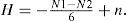
Starting from n minimal shapes, then N1i-N2i6=n. When adding N1 and N2 we have

To numerically validate Theorem 5(b), let us use the set of two shapes shown in Figure 10. As we can see, the total number of holes is eight. Let us verify this by applying Theorem 5(b). From Figure 10 we can easily verify that that N1=53 and N2=89 and H=-53-896+2=8. This numerically validates Theorem 5(b).
.")
The main result concerning the computation of the Euler number of a shape or a set of shapes composed of hexagonal cells can be stated as follows:
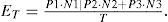
Theorem 6The Euler number E of n binary shapes composed of hexagonal cells is always given as follows:
Proof
From Equation (1) and by Theorem 5(b):

To numerically validate Theorem 6, let us use again the set of two shapes shown in Figure 10. As we can see, the Euler number for this set of shapes is -6. Let us verify this by applying Theorem 6. We have seen that N1=53 and N2=89 and E=53-896=-6. This numerically validates Theorem 6.
5Unifying resultEquations (4) and (7) can be unified into one sole equation as follows:
Corollary 1Let T denote the number of sides of a composing cell (T=4, for objects composed of square cells and T=6, for objects composed of hexagonal cells). The Euler number ET of n binary shapes composed of cells with T sides is given as follows:
The value of T determines the values of the weights: P1, P2 and P3. Thus, if
Proof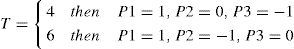
From Theorems 3 and 6.
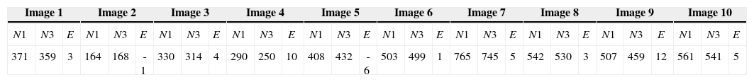
6Examples with imagesThis section discusses the computation of the Euler number on some images. For this, the 10 binary images of 128×128 pixels shown in Figure 11 are used.

To appreciate the robustness of the proposal, the number of objects and the number of holes, as can be seen, are different from image to image. Equation 4 has been applied to each image. To compute Equation 4 on each image, the algorithm shown in the Appendix was used.
Table 2 summarizes the computation results. Note that in all cases, as predicted by Equation 4, the right value for the Euler number of each image has been obtained.
The Euler Number of Different Test Images.
| Image 1 | Image 2 | Image 3 | Image 4 | Image 5 | Image 6 | Image 7 | Image 8 | Image 9 | Image 10 | ||||||||||||||||||||
|---|---|---|---|---|---|---|---|---|---|---|---|---|---|---|---|---|---|---|---|---|---|---|---|---|---|---|---|---|---|
| N1 | N3 | E | N1 | N3 | E | N1 | N3 | E | N1 | N3 | E | N1 | N3 | E | N1 | N3 | E | N1 | N3 | E | N1 | N3 | E | N1 | N3 | E | N1 | N3 | E |
| 371 | 359 | 3 | 164 | 168 | -1 | 330 | 314 | 4 | 290 | 250 | 10 | 408 | 432 | -6 | 503 | 499 | 1 | 765 | 745 | 5 | 542 | 530 | 3 | 507 | 459 | 12 | 561 | 541 | 5 |
This paper has introduced a very simple method to calculate the Euler number of a binary shape following its contour description. The numbers of faces touched by a contour vertex have been employed as a fundamental element in the method. The new method features simplicity and originality. The Euler number computation for a digital shape or a digital binary image is very easy to compute through Equation 4.
The formal support of the proposal is based on four main theorems. Examples with simple shapes and with several real binary images have been provided to visually appreciate the robustness of the method.
As a supplement, equations are provided for computing the Euler number of a binary image composed of hexagonal cells. In these cases, simple examples have been given to verify the overall operation of these equations.
A unifying result has been also provided that allows seeing that when choosing the appropriate weights, the corresponding equation for the case of shapes composed of squared of hexagonal cells can be selected.
Finally, for a given image b, because the computations are independent from pixel to pixel, the computation of the Euler number can be done in two phases by using a parallel architecture, such as a GPU machine. During the first phase numbers N1 and N3 for each pixel are computed. During this same phase, each partial value is next divided by T. Finally, during the second phase, both results are subtracted to get the desired value for E.
R. Santiago and M. Pérez thank the ITL and the UDEG, respectively, for the support. H. Sossa thanks SIP-IPN and CONACYT for the economical supports under grants 20121311, 20131182 and 155014, respectively. E. Rubio thanks SIP-IPN for the support under grant 20131505. We all thank the reviewers for their comments on the improvement of this paper.
The following algorithm in Java has been used to compute numbers N1 and N3 from a binary image. From these numbers, the Euler number of a binary image can be thus obtained.
private void count(int [] unosTres) {
int points1=0;
int points3=0;
for (int i=1; i<(image.length - 1); i++) {
for (int j=1; j<(image [0].length - 1); j++) {
if (image[i][j]==0) {
if ((image[i][j - 1] !=0) && (image[i - 1][j] !=0)) {
points1++;
}
if ((image[i - 1][j] !=0) && (image[i][j+1] !=0)) {
points1++;
}
if ((image[i][j+1] !=0) && (image[i+1][j] !=0)) {
points1++;
}
if ((image[i+1][j] !=0) && (image[i][j - 1] !=0)) {
points1++;
}
}
else {
if ((image[i][j - 1] !=255) && (image[i - 1][j] !=
255)) {
points3++;
}
if ((image[i - 1][j] !=255) && (image[i][j+1] !=
255)) {
}
if ((image[i][j+1] !=255) && (image[i+1][j] !=
255)) {
points3++;
}
if ((image[i+1][j] !=255) && (image[i][j - 1] !=
255)) {
points3++;
}
}
}
}
unosTres[0]=points1;
unosTres[1]=points3;
return;
} // End