


This paper shows the developing process of an anti-vibration system, from its conception up to the construction of a experimental prototype. Special features and constraints that must be considered are specified, including a description and theoretical foundation of the working principle, a geometrical proposal and a component selection process, in order to ensure the effective operation of the system complying required specifications. Finally, the combination of these elements are used to design and build an experimental prototype capable to simulate the behavior of an anti-vibration system for ensuring the safe transfer and reliable operation of mammography equipment on board of a mobile medical unit.
En este trabajo se presenta el proceso de desarrollo de un sistema antivibratorio, desde su concepción (necesidad de aplicación y requisitos) hasta la construcción de un prototipo experimental que debe cumplir con ciertas características y restricciones de diseño y funcionamiento. Este proceso consta de la descripción de las condiciones de traslado de un mastógrafo instalado en una unidad médica móvil y del principio de funcionamiento de un sistema antivibratorio y su fundamento teórico, así como de una propuesta de geometría del sistema antivibratorio y de un proceso de selección de componentes. Con ello, se estaría asegurando el funcionamiento eficaz del sistema, para que cumpla con el objetivo de aislar de vibraciones el mastógrafo durante su traslado. Finalmente, se cuenta con el diseño y fabricación de un prototipo experimental, capaz de simular con él el desempeño necesario para garantizar el traslado seguro y operación confiable de un mastógrafo a bordo de una unidad médica móvil.
Breast cancer is currently the most common cancer and the highest mortality cause among women in the world. The epidemiological scenery of this disease in the Mexican population was transformed in the last 50 years and breast cancer has become a public health problem.
Among the procedures intended for detection of breast cancer, mammography is the only technique that can provide a sufficiently timely detection. However, only 22% of women aged 40 to 69 years underwent a mammogram in the past year. There are barriers on both the demand and supply sides. For this reason health programs have been implemented to bring the mammograms to women as much as possible, highlighting the mobile medical units for mammography (MMU) (Figure 1).

Evidence shows that the quality of a mammogram performed on-board of a mobile unit decreases with time more than with a fixed mammography equipment. This could be due, among other reasons, to the adverse conditions of mechanical vibrations under which this equipment is subjected, besides that there is no standards governing the quality of mammography conducted using this equipment.
So, it is desirable to study the effects of mechanical vibrations on mammography equipment, in order to develop an anti-vibration system to improve the service time of mobile mammography equipment and encourage the improvement for its transfer and operation. [1]
2MethodologyFirst of all, it is necessary to know the system requirements, both physical and functional. The physical requirements are determined by the geometry of the base of the mammography equipment and the MMU height. The functional requirements are limited by the mechanical vibrations -among others influence factors-transmitted from the chassis of the MMU to the base of the mammography equipment.
2.1Physical requirementsThe study of physical requirements is defined by dimensional factors. The maximum MMU internal height is a little larger than that of the mammography unit, so it will result in that the smallest height available of the anti-vibration system is required.
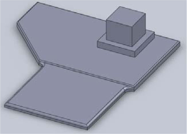
The mammography equipment base geometry (Figure 2.) is the other important factor of the physical requirements. [5]
2.2Functional requirements
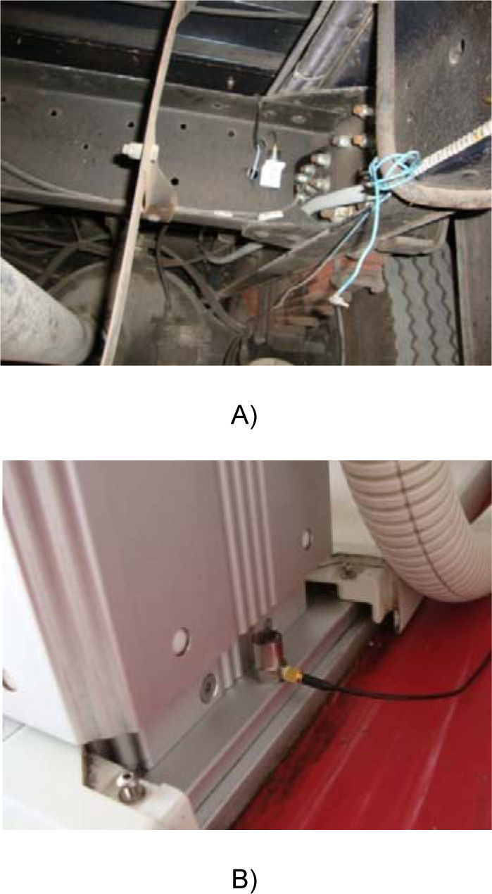
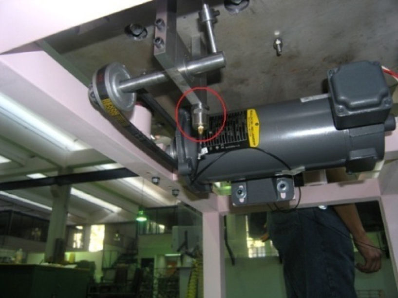
Measurements of mechanical vibrations were obtained by mean of two vibration accelerometers and a portable two channel spectrum analyzer, located on the chassis of the mobile unit and on the base of the mammography equipment as shown in Figure 3.
 chassis of the MMU and B) base of mammography equipment")
The time vibration signals in both selected points were recorded simultaneously with the spectral analyzer, to process them formerly with the spectrum analyzer software and then with MATLAB.
The vibration measurements were obtained in three axes: one vertical (Z axis) and two horizontal (X and Y axes) coincident with the width and length of the mobile unit, respectively.
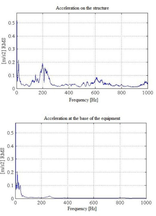
The most significant results were those obtained on Z axis during mammography equipment transportation (Figure 4).

It is observed from the graphics that, during the transportation, the vibrations are mainly attenuated from 50Hz frequency, and that the maximum MMU peak frequency is 11.717Hz. [6]
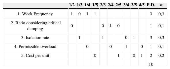
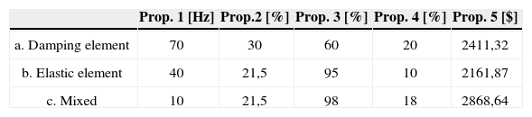
3Selection ProcessA selection process using a decision matrix was made to find the system that best suits the problem requirements [3] for three devices including: energy dissipating element, elastic element and mixed. The properties that were considered for entry into the decision matrix were: work frequencies of the system, ratio considering critical damping, isolation rate, permissible overload and cost per unit.
This process is based initially on a number of decisions taken by a number of properties, in this particular case, the system properties.
The number of decisions N is given by the following equation:
where n= number of properties, in this case 5, so:
Now it is necessary to define two concepts:

And

The decision matrix will be filled out to compare each one of the properties respect to the others and assigning 1 to the most relevant and 0 to the least one, resulting Table 1 and Table 2.
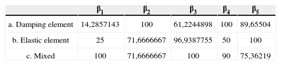
The next step is to define another factor, with the following conditions:
- a)
If the largest magnitude value is the best:
This factor is used for properties 2, 3 and 4.
- a)
If the lower value in magnitude is the best:
This factor is used for properties 1 and 5.
Then the factor β matrix results are shown in Table 3.
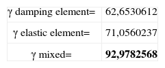
Finally the system performance rate (γ) is obtained by the next equation:

This factor will give the chosen one system over the others and where the maximum MMU numeric value is the best. So the performance rates of the three systems chosen are the following (Table 4):
Thus it can clearly be seen that the performance rate of the mixed system is greater than the rate of the other two, in such a way that this results should be considered the base of the development of an anti-vibration system. [7]
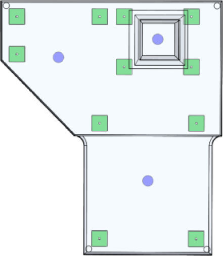
4Transmissibility analysisTo guarantee the function of a control vibration system to perform as expected, it is required to do an analysis based on certain characteristics. First a configuration proposal (Figure 5) is made based on the previous processes.

With this configuration is possible to make a transmissibility analysis [4] based on 5 known parameters (Figure 6):
- 1.
Weight (Mammography equipment weight) = 250Kg
- 2.
Characteristic frequency (Functional requirements) = 11.717Hz
- 3.
Spring stiffness (Spring's supplier information) = 53 938.5N/m
- 4.
Ratio of critical damping (Damper's supplier information) = 0.143
- 5.
Number of springs (Configuration proposal) = 3

Relationship between the maximum amplitudes of the applied and transmitted forces is known as Transmissibility coefficient; its dimensionless form is expressed as:
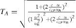
The coefficient of transmissibility should be preferably lesser than unit, so:
which means that:

Equation (9) is the relationship between the forcing frequency ω and the undamped natural frequency ωn, known as frequency ratio, r, which should be preferably greater than 2; and cccr, in equation (7), is the well known damping ratio, ζ.
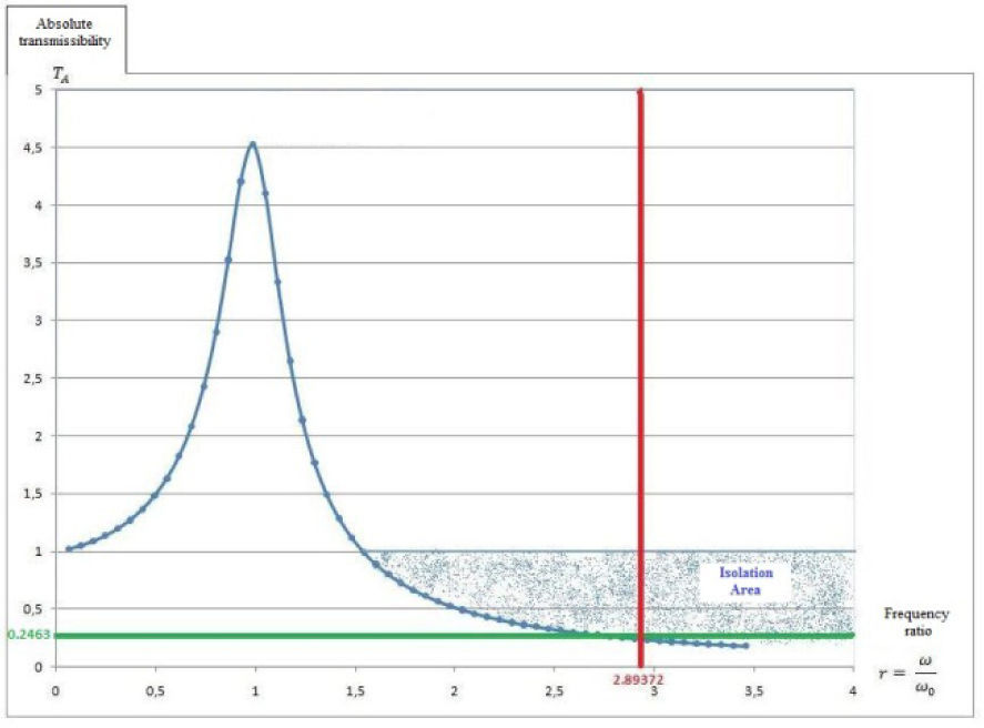
Then, with these data the characteristic curve of the anti-vibration system was built, where Absolute Transmissibility and Frequency Ratio are shown in vertical and horizontal axes, respectively, resulting frequencies from 0.25 to 14(Hz). [2–4]
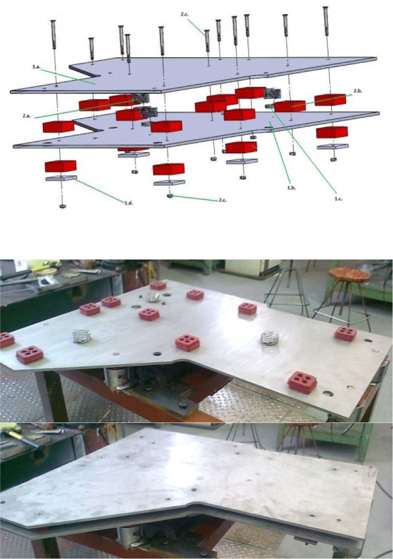
5Manufacturing and assemblyTo start manufacturing, selection process and transmissibility analysis must be considered to reach a first proposal of physical system, which will have the advantage of being under experimental conditions similar to those which mammography equipment on board a MMU is subject to, in such a way to corroborate previously obtained real data. Anti-vibration system assembly is shown below (Figure 7.)
6Tests and results
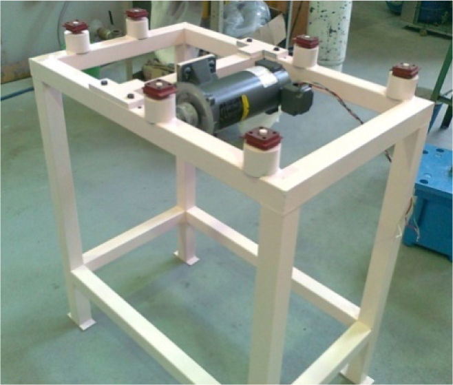
A test bench was built (Figure 8) in order to be able to produce similar vibrations to those shown in Figure 4.

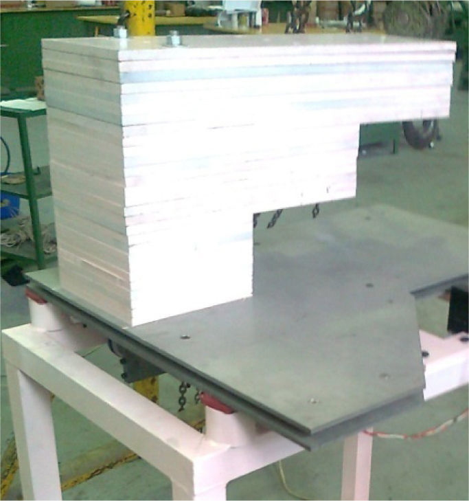
Furthermore, for testing the system with the necessary conditions for its proper functioning, steel plates were used (Figure 9) to simulate the mammography equipment weight (250kg):
")
The tests were made in the same way as reported in section 2.2. Measurements were taken placing one accelerometer below the base of the system and a second one over the anti-vibration support, aside the steel plates (Figure 10). [6,8,9]
 Accelerometer below the base of the anti-vibration support system B) Accelerometer above anti-vibration support system")
 Accelerometer below the base of the anti-vibration support system B) Accelerometer above anti-vibration support system")
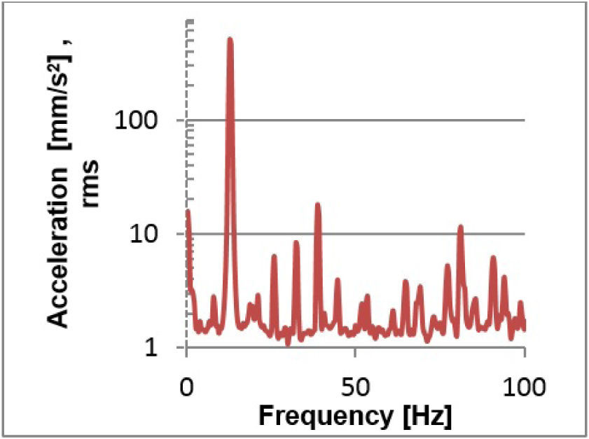
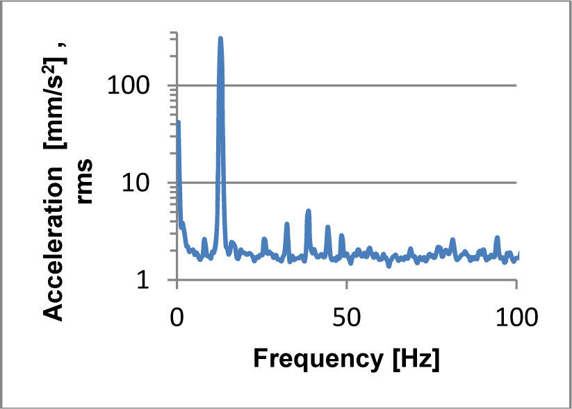
The corresponding vibration spectra for both accelerometers were obtained. Results are shown in Figures 11 and 12.
7Conclusions

As it could be expected, selection process confirmed that mixed system results the best option, since it allows working in the required frequencies as well as the highest isolation percentages, that were the two properties with the highest qualification in Table 1.
There is no information in the Operator's manual about the parameters of vibration that the mammography equipment could be exposed to; however, from the transmissibility analysis and at the frequency which the analysis was made (the characteristic frequency) the proposed system behaves in the range of isolation area, satisfying the two necessary conditions for testing the functionality of a vibration control system, namely:
- 1.
Absolute transmissibility: TA=0.2463<1
- 2.
Frequency ratio: r=2.89372>2
Springs of new technology were used (undulated springs REDUX®) that are able to reduce almost in half the operating height of the conventional springs. This is important because the dimensional room restrictions. The dampers are made of a composite of neoprene and nitrile, which combine adequately with the springs, providing the expected vibration isolation behavior.
Finally, with regard to the results obtained from the measurements made at both points in Figure 10 it is worthy of note that in both graphs (Figures 11 and 12) a peak is appreciable at a frequency of 12.8Hz where there is a maximum MMU acceleration amplitude, around which was planned to test the system, near to the same functional requirements (acceleration amplitude of 0.2ms2 and a frequency of 11.717Hz at which the tests were conducted, very close to information taken from the MMU (Figure 4), within a variability less than 10%.
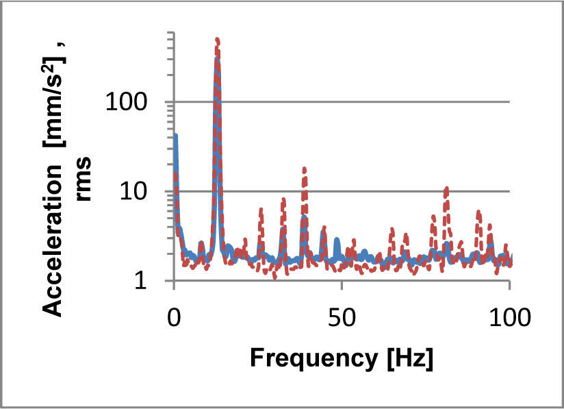
From a frequency of 12.8Hz, acceleration of 20mms2 are almost reached measuring below the damping system (Figure 11); while in the spectrum graph measuring above system (Figure 12), maximum MMU amplitudes reached are perceived about 4mms2. Furthermore, at the fundamental frequency (12.8Hz) it presents a clear damping (Figure 13), as in the performed measurement under the system a maximum MMU amplitude of 502.9mms2 is reached, while in the above measuring system the maximum MMU amplitude reached was 303mms2.
