


This item presents the real-time programming of a prototype robot to control its movement from one moment to another without showing response delays. Contributing to this is the communication protocol developed in our laboratories and feasibility of being implemented in the future with wireless control via radio frequency, and to present the progress to date have been obtained.
Se presenta la programación en tiempo real de un auto prototipo para controlar su movimiento de un momento a otro sin presentar retardos de respuesta. La contribución a este mismo es el protocolo de comunicación desarrollado en nuestros laboratorios y la factibilidad de ser implementado en un futuro con control inalámbrico, a través de radio frecuencia, así como presentar los avances que hasta el momento se han obtenido.
Nowadays the majority of mechatronic systems are developed and manufactured have constant changes in design or being designed with technology circuits or transistor logic gates which it could operate an electronic system. Constant changes in technology impact manufacturing processes of electronic devices making them increase its potential in its operation, such as microcontrollers. Today all electronic system tends to be simplified at low cost components with a reduced manufacturing time. The microcontrollers achieves perspectives, and has a better control in mechatronic systems. For example, this can be seen in DVD'S, digital cameras, automotive control systems, satellites, television, washing machines, and others.
The use of microcontrollers for the design and implementation of mechatronic systems aims to maintain a better control and reduce the manufacturing cost, and increase performance. The prototype design will be controlled automatically without the need a person is aware or its performances with the appliance of sensors. In this first report we present the prototype robot control by software (graphical atmosphere, the prototype perimeter movement, etc.), and submit the final implementation of the project will be introduced in events like this.
With this kind of project we can make some applications, for example, measurement of distances using the diameter of the cars' tires to calculate the distance it has travelled and to be able to display information on an LCD screen, in the same way moving heavy objects from one location to another without coalition, etc.
In section II of this item presents the description block of the system, components parts in hardware and software. Section III shows the code used to control the robot. Section IV shows the results and comments. Section V presents the conclusions of the work and future work.
2DescriptionThe development of the project becomes from the necessity to handle a car with a microcontroller (microcontrollers) for our case we use the PIC16F84, the first stage is a program that is developed and communication protocol to conduct self-control from the PC using the language C programming and the development of the communication protocols, protocols for data transmission and reception.
Control of the car through the hardware and software is described below.
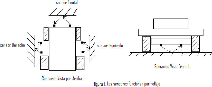
From the keyboard of the PC we will have the total control of the prototype with a small settled graphic that has been developed in C language menu hardware containing the car is a 16f84 PIC microcontroller, which contains a program that translates data from the computer to the car robot would shift in a definite sense autonomy purposes the car must have four sensors, two sensors will be found to the left and two sensors to the right opposite a third sensor is placed at the bottom and the fourth sensor will be placed as shown in figure 1.

The sensors that were used are the type of infrared sensors, a LED was placed (transmitter) and a photodiode (receiver), the functioning of the devices is simply reflected at the nearest surface of the car, a treatment is given to the signal to give us 5volts to enter by the port to the microcontroller, which in this case this is the input port and port B is output.
The following concept describes the connection in each of the pins of the input and output ports of the microcontroller.
PortA. (Input). The products are connected to portA the following sensors:
Bit0 upper front sensor
Left sensor bit1
Right sensor Bit2
Bit3 inferior frontal sensor
Bit4 not used
Bit5 not used
PortB. (Output). In the port B is connected to the following sensors:
Bit0 1 st line stepper motor
Bit1 2nd line stepper motor
Bit2 3rd line of stepper motor
Bit3 4th line of stepper motor
Bit4 direction of the cart
Bit5 direction of the cart
Bit6 not used
Bit7 not used
When a photodiode detected the infrared, it ceases to flow a small amount of current which is amplified by means of a first transistor, which in turn, said current continues to circulate in a second transistor, which will provide a voltage, so that we give treatment to the voltage to keep it and treat 5volts now as a logic level high (1 logic) 5volts and low (0 logic) when the voltage is zero volts.
Under these conditions the data are provided in the form of logical ones and zeros, for the port to the microcontroller to manipulate the engine that gives traction or displacement of the car and the address. The control stage stepper motor, consisting of four small power transistors receiving the pulses that are transmitted from the port B with the first four transistors is increased the current will be used to activate the bases of the second stage transistors medium power, which manipulate the current demanded the stepper motor.
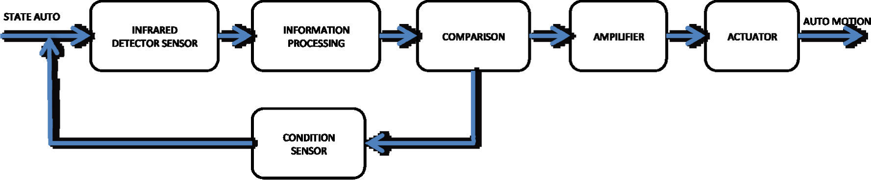
In Figure 2 shows the block diagram indicating the operation mode of the car because a sensor with other sensors performs the same function.

As shown in Figure 2, the order is maintained in a state that can be static, rotating one turn, moving in reverse or forward correctly, so that when a sensor detects the infrared, the microcontroller will be processing the first information that arrives at port A, according to data that is taken into the port, the microcontroller will compare the data in and send new data on port B, four bits are taken from this port, connect to the amplifier stage to command the four bits to the actuator in this case the stepper motor in such a way that causes the movement of the car. The microcontroller is constantly monitoring the status of sensors to make decisions by varying the state of the actuator and therefore the motion of the car.
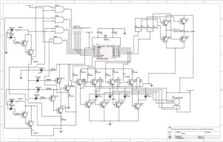
Figure 3 shows the electronic control diagram of the car. In this diagram you can see a serial connector for connection to PC, a program in C language controls i.e. the car, where by means of the keyboard have full control and you could see on the screen the behavior of the car PC.
2.2C programming code
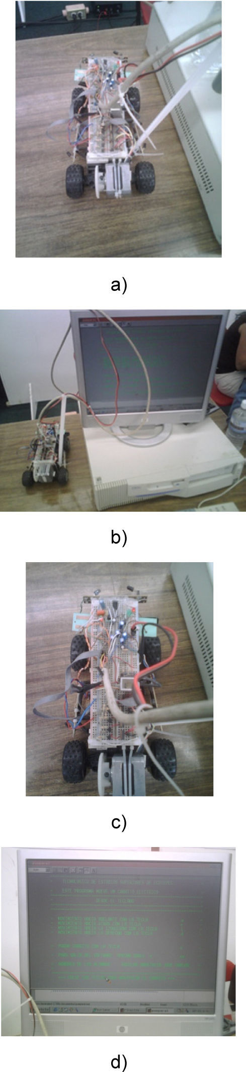
Shows the programming code in C language used for the development of this work, which can observe the syntax and the implementation thereof, shown in Figure 4d.
# Include
# Include
# Include stdio.h
Stdlib.h
main ()
{
textcolor (10);
textbackground (3);
/ * Int data; * /
char key;
clrscr ();
do {/ * start menu * /
gotoxy (10.3);
puts
("=====================================
========== ================= \ n ");
gotoxy (10.4);
puts ("= MOVING THIS PROGRAM CART ELECTRIC A = \ n"); gotoxy (10.5); puts
("=====================================
========== ================= \ n ");
gotoxy (10.6);
puts ("= KEYPAD = \ n");
gotoxy (10.7);
puts
("=====================================
========== ================= \ n ");
gotoxy (10.8);
puts
gotoxy (10,10);
puts ("= MOVING FORWARD WITH THE KEY a = \ n");
gotoxy (10,11);
puts ("= MOVING BACK TO KEY = r \ n");
gotoxy (10,12);
puts ("= MOVING TO THE LEFT WITH THE KEY i = \ n");
gotoxy (10,13);
puts ("= MOVING RIGHT WITH THE KEY d = \ n");
gotoxy (10,14);
puts ("= STOP SHOPPING WITH KEY = p \ n");
gotoxy (10,15);
puts ("= SOFTWARE TO EXIT PRESS se = \ n");
gotoxy (10,17);
puts ("= NAMES OF STUDENTS: AGUILAR JOSE CARLOS ANASTACIO = \ n");
gotoxy (10,18);
puts ("== \ n");
gotoxy (10,19);
puts
("=====================================
========== ================= \ n ");
gotoxy (10.22);
printf ("*** PRESS THE KEYS TO HANDLE THE
CART *** \ n");
gotoxy (19,23);
scanf ("% c", & key);
/ * Textcolor (4), * /
/ ************************************************* ******* /
/ * Scanf ("% d", & data);
printf ("DATA input: \ n");
gotoxy (35.23) * /
/ ************************************************* ******* /
clrscr ();
gotoxy (10.24);
printf ("decimal point is% d \ n", key);
clrscr ();
switch (key)
{
case 97: / * point to * /
outportb (956.0 x01);
getchar ();
break;
case 105: / * point i * /
outportb (956.0 x02);
getchar ();
break;
case 100: / * point d * /
outportb (956.0 x08);
getchar ();
break;
case 114: / * letter r * /
outportb (956.0 x04);
getchar ();
break;
case 112: / * point p * /
outportb (956.0 x0);
getchar ();
break;
/ * Case 101:
outportb (956.0 x0);
break; * /
default:
clrscr (), / * none of the letters of the menu * /
gotoxy (15,10);
printf ("*** CLICK THE OPTIONS THAT ARE IN THE MENU *** \ n");
gotoxy (35.12);
scanf ("% d", & key);
outportb (956.0 x0);
clrscr ();
/ * Getche (), * /
}
}
while (tecla! = 101);
}
3ResultsThe results to this report are shown in Figures 4a to 4d, which describe the progress of each of the objectives achieved.
4Conclusions
The conclusions of the work are specifically:
It shows a great performance in the management and control of the robot car.
It was possible to communicate with the PIC C language, through a communication protocol.
Migration to an improvement of the project is viable.
Objectives achieved.
We work on improvements to our design project.
This project is open for further work on him, now implementing data transmission via radio frequency, other hands from the PC; you enter different data for each movement and the data obtained in the parallel port output to be introduced but other communication card. Radiofrequency data to send the air and the cart by means of an antenna will receive the data and execute the information so as to perform the movement of the car.
Research is also self-control through the Internet, placing a video camera now, so you can appreciate the image where the car is traveling robot.