


In this study, a multilevel inverter was designed and implemented to operate a stand-alone solar photovoltaic system. The proposed system uses pulse-width modulation (PWM) in the multilevel inverter to convert DC voltage from battery storage to supply AC loads. In the PWM method, the effectiveness of eliminating low-order harmonics in the inverter output voltage is studied and compared to that of the sinusoidal PWM method. This work also uses adaptive neuro fuzzy inference (ANFIS) to predict the optimum modulation index and switch angles required for a five level cascaded H-bridge inverter with improved inverter output voltage. The data set for the ANFIS-based analysis was obtained with the Newton-Raphson (NR) method. The proposed predictive method is more convincing than other techniques in providing all possible solutions with any random initial guess and for any number of levels of a multilevel inverter. The simulation results prove that the lower-order harmonics are eliminated using the optimum modulation index and switching angles. An experimental system was implemented to demonstrate the effectiveness of the proposed system.
Multilevel inverters play a major role in numerous applications such as medium-voltage drives, renewable energy system, grid interfaces, and flexible AC transmission devices [1]. A multilevel inverter is a familiar power electronic converter that can synthesize a desired output voltage from several levels of DC voltages as input source. Much research work has been devoted to equal DC sources and little to unequal DC sources in the multilevel inverter circuit topologies. Based on these identical voltage levels and proper pulse-width modulation (PWM) control of the switching angles, a staircase waveform can be synthesized. The reduction of switching losses in the inverter devices due to the on and off switch operation during one fundamental cycle is one of the major benefits of the staircase output waveform. Moreover, with reduced switching frequencies, low-order frequency harmonics can be observed in the staircase output voltage [2]-[8].
Although many approaches have focused on eliminating low-order frequency harmonics, the selective harmonic elimination (SHE) PWM method [9]–[10] is preferred widely in multilevel inverters [11]-[12]. The selective harmonic elimination pulse-width modulation switching (SHEPWM) technique can be used to compute switching angles by solving the nonlinear transcendental equations characterizing harmonics [13]-[14]. Many iterative techniques have been reported to solve the nonlinear transcendental equations resulting in only one solution set or multiple solutions by assuming a proper initial guess [15]-[16]. Several traditional methods can be used to estimate switching angles; however, a few of them may be computationally expensive. As soft computing techniques such as artificial neural networks (ANNs) and adaptive neuro-fuzzy inference system (ANFIS) learn and adapt to a great diversity of data, it can be an excellent option to estimate switching angles [17]. Although microcontrollers are used for the solution of applications of intermediate complexity, recently FPGA processors are preferred widely in areas with high integration as well as compact and flexible extension of the system [18].
However, to the authors knowledge, the adaptive neuro-fuzzy inference system (ANFIS)-based prediction of switching angles in five-level inverter has not been addressed so far. The case study is performed to develop the stand-alone multilevel inverter system connected to solar panels. The DC-DC converter was used to regulate the DC voltages from solar panels, which varied because of changes in solar radiation. Previous results of a study in prediction of solar radiation and sizing of panels for various regions of Tamilnadu, India [19]-[20] have now been utilized for the application of the stand-alone multilevel inverter system. An attempt has been made to train the ANFIS prediction model to explore the prediction of switching angles that can produce the desired fundamental voltage by eliminating the third-order harmonics. Moreover, the experimental work has been carried out to validate the proposed method.
The paper is organized as follows. The next section presents the structure of the multilevel inverter and the SHE-based modulation adopted to eliminate the higher-order harmonics. It also depicts the determination method for switching angles that can be used to frame the data set for ANFIS training. Section 3 describes the state-of-art ANFIS predicition method. Section 4 presents the experimental work and its results.
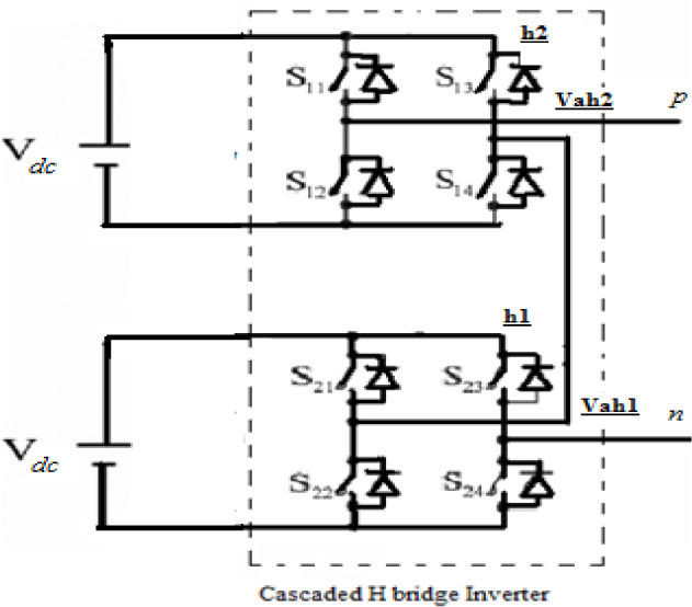
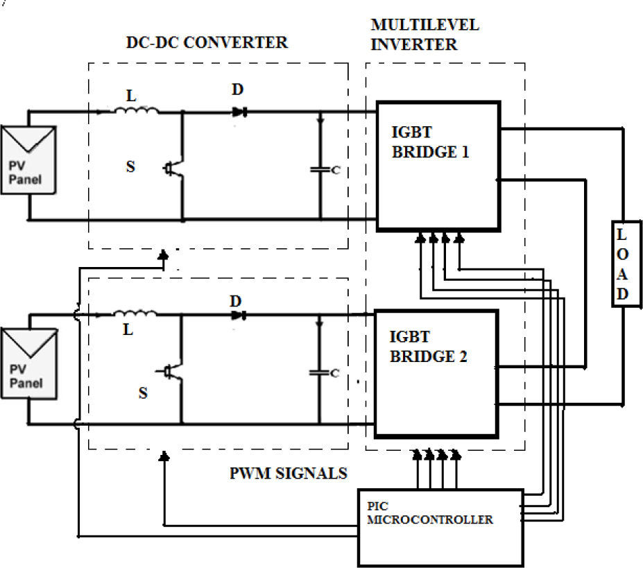
2Multilevel inverterIn the family of multilevel inverters, the cascade multilevel inverter is one of the significant topologies. It requires less components, a modular structure with a simple switching strategy, and an easily adjusted number of output voltage levels by adding or removing full-bridge cells [21]-[22]. The cascade multilevel inverter is composed of a number of H-bridge inverter units with a separate DC source for each unit and can be connected in cascade to produce a near sinusoidal output voltage waveform using the proper modulation scheme.as shown in Figure 1.

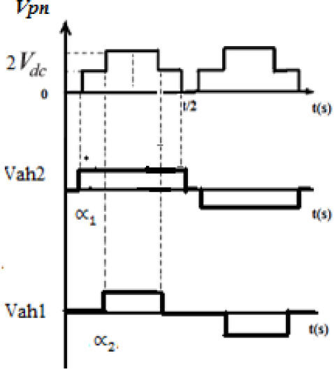
The number of levels in the output phase voltage is manipulated by 2s+1, where s is the number of H-bridges units utilized. The system chosen in this study bears two full-bridge inverters, each connected to 4 solar panels of 85 Wp capacity. Figure 2 shows the output voltage waveform of the five-level cascaded H-bridge inverter. The magnitude of the AC output phase voltage is given by vpn=vah1+vah2 where vah1 and vah2 are the voltages corresponding to the switching angles, α1 and α2.

Although there are different switching strategies available for minimization and elimination of harmonics [23]-[24], in this work, the sinusoidal pulse-width modulation (SPWM) and selective harmonic elimination pulse-width modulation (SHEPWM) were developed to minimize and eliminate the low-order harmonics, respectively.
2.1Sinusoidal pulse-width modulation (SPWM)The SPWM technique is one of the primitive techniques; it is used to suppress harmonics present in the quasi-square wave. In SPWM, a carrier wave is compared with a reference wave [25]-[26]. The reference wave corresponds to the desired fundamental frequency at the output and the triangular wave determines the frequency with which values are switched. By changing the frequency of the carrier wave, higher switching frequencies can be obtained. In order to avoid the elimination of the even harmonics, the carrier frequency should always be an odd multiple of three.
2.2Selective harmonic elimination pulse-width modulation (SHEPWM)Traditionally, the Fourier series expansion for any output of the system can be expressed as in Equation (1):

As it is an odd symmetric function, the value of a0 =an=0 (amplitude of the even harmonic component) and bn. The Fourier series expansion of the waveform with the same magnitude than all the DC sources can be expressed as in Equation (2):
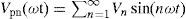
where, Vn is the amplitude of the harmonics. The magnitude of Vn becomes zero for even-order harmonics because of an odd quarter-wave symmetric characteristic:
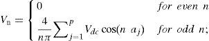
Where is the switching angle limited between and Vdc is the voltage of DC sources which are of the same magnitude. Subsequently, Vn becomes
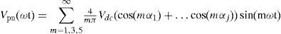
Where j is the number of switching angles and m is the harmonic order.
Ideally, in the multilevel inverters, there can be k number of switching angles, in which one switching angle can be used for fundamental voltage selection and the remaining (k-1) switching angles can be used to eliminate few prime low-order harmonics. Moreover, the modulation index is defined as the ratio fundamental output voltage V 1 to the maximum obtainable voltage V max as shown in Equation (5):
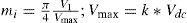
The range of is considered as the fundamental linear modulation component. For the five-level cascade inverter, k value is 2 or two degrees of freedom are available; one degree of freedom can be used to control the magnitude of the fundamental voltage and the other can be used to eliminate the third-order harmonic component as it contributes more to the total harmonic distortion. The following equations (6)–(7) can be obtained from the above-stated conditions to manipulate the switching angle for performing selective harmonic elimination:
2.2.1Newton-Raphson Method

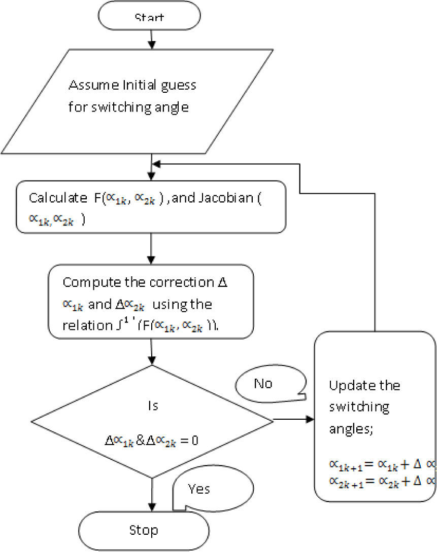
These nonlinear polynomial equations can be solved by the iterative Newton-Raphson method to determine the switching angles, α1 and α2. The initial guess for switching angles (α1, α2) lies in between 0 and π/2. The flow chart for the Newton-Raphson method can be used to compute all possible solutions without any computational complexity as shown in Figure 3.

The NR method approach is capable of finding analytical solutions for limited ranges. It gives a more approximate solution in providing a smooth data set that is needed for the ANFIS training.
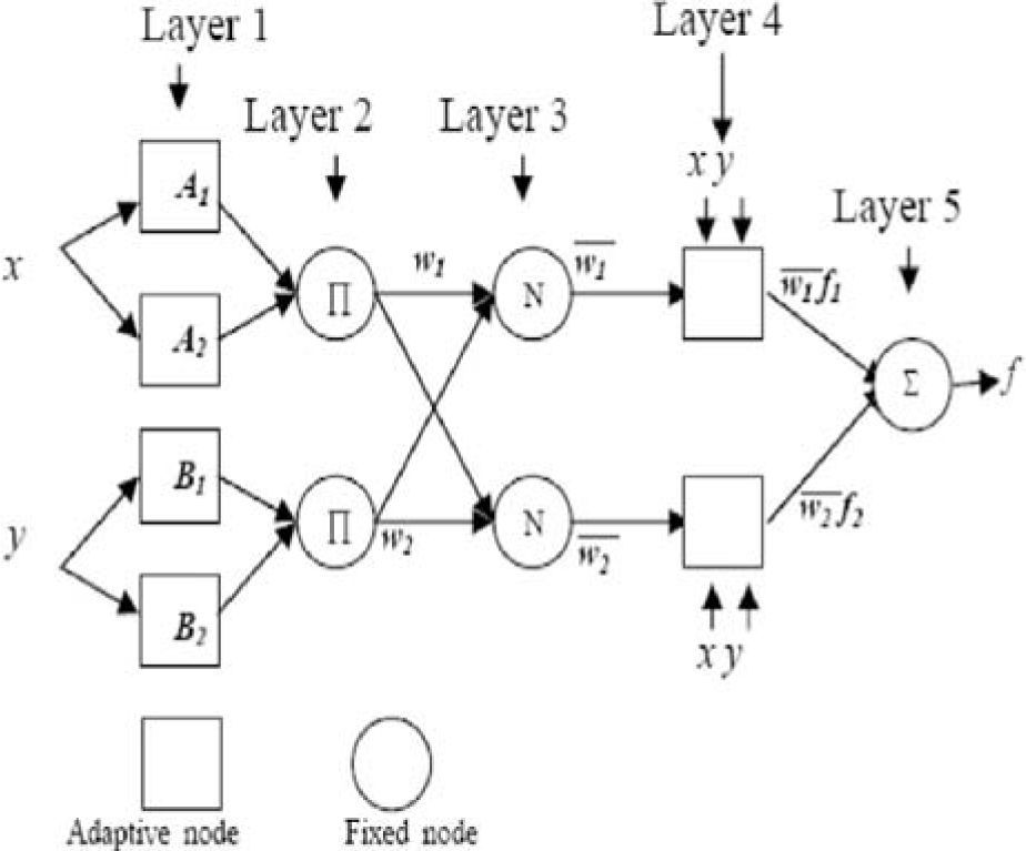
3Adaptive neuro-fuzzy inference system3.1State-of-The-Art : ANFIS theoryANFIS is a hybrid soft computing model composed of a neuro-fuzzy system in which a fuzzy inference (high-level reasoning capability) system can be trained by a neural network-learning (low-level computational power) algorithm. ANFIS has the neural network’s ability to classify data in groups and find patterns and further develop a transparent fuzzy expert system. Moreover, ANFIS has the ability to divide and adapt these groups to arrange a best membership function that can cluster and deduce the desired output within a minimum number of epochs [27]-[28]. The fuzzy inference system can be tuned by the learning mechanism. A given input/output data set, ANFIS constructs a fuzzy inference system (FIS) whose membership function parameters can be tuned (adjusted) using either a back-propagation algorithm alone or in combination with a least squares type of method. Figure 4 shows the ANFIS architecture used in this work. This system has two inputs x and y and one output, whose rule is.

Rule i:

where fi is the output and pi, qi and ri are the consequent parameters of ith rule. Ai and Bi are the linguistic labels represented by fuzzy sets. The output of each node in every layer can be denoted by 0il where i specifies the neuron number of the next layer and l is the layer number [29]-[30]. In the first layer, called fuzzifying layer, the linguistic labels are Ai and Bi. The output of the layer is the membership function of these linguistic labels and is expressed as.

where μAi(x) and μBi(y) are membership functions that determine the degree to which the given x and y satisfy the quantifiers Ai and Bi. In the second layer, the firing strength for each rule quantifying the extent to which any input data belongs to that rule is calculated [31]. The output of the layer is the algebraic product of the input signals as can be given as

“∩” denotes a fuzzy ∩ norm operator which is a function that describes a superset of fuzzy intersection (AND) operators, including minimum or algebraic product. In this study, an algebraic product was used. In the third layer, called the normalization layer, every node calculates the ratio of the ith rule’s firing strength to the sum of all rules’ firing strengths [32].
In the fourth layer, the output of every node is


The ANFIS learning algorithm employs two methods for updating membership function parameters [34-35]:
- •
A hybrid method consisting of back-propagation for the parameters associated with the input membership functions, and least squares estimation for the parameters associated with the output membership functions.
- •
Back propagation for all parameters.
In order to improve the training efficiency, a hybrid learning algorithm can be applied to justify the parameters of the input and output membership functions. The only user-specified information is the number of membership functions for each input and the input–output training information. Hence, the output can be written as
3.2Design of the Proposed ANFIS Model
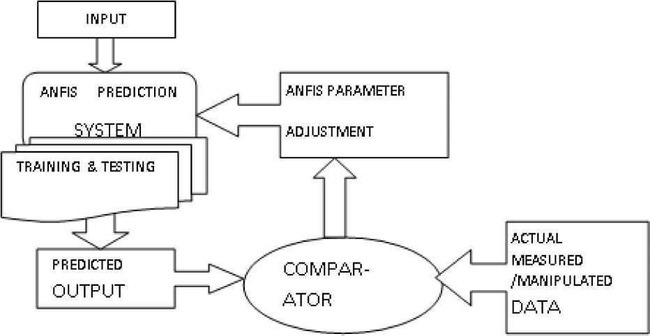
The design of the ANFIS model was developed by using MATLAB 7.5.0.3402 (R2007) software version. In this study, the ANFIS model was used with a hybrid learning algorithm to identify parameters of Sugeno-type fuzzy inference systems. It applies a combination of the least-squares method and the back-propagation gradient descent method for training (fuzzy inference system) FIS membership functions (MFs) parameters to estimate a given training data set. Three gbell-shaped membership function was assigned for training FIS membership functions. The model was trained with data set framed by analytical method and the genetic algorithm method. Figure 5 shows the proposed ANFIS prediction model. In this work, the input variables are array voltages from the solar panel and the switching angles.
3.2ANFIS simulation results
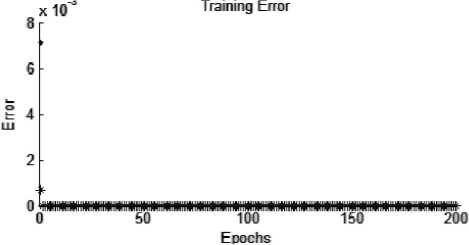
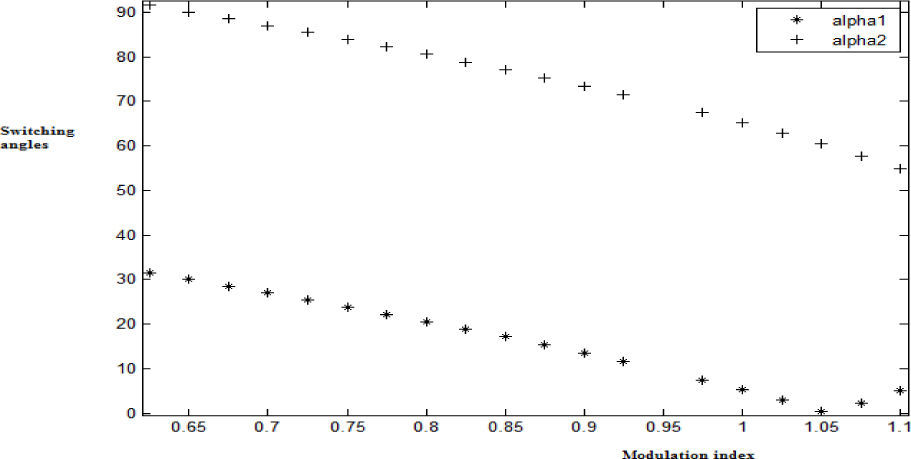
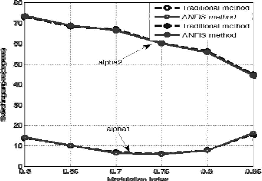
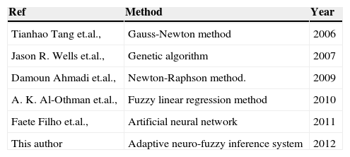
The trained ANFIS network can be observed to experience a negligible training error of 0.00066062 as shown in Figure 6. The switching angles α1 and α2 along with the modulation index in the range of 0.65<mi<1.1, which were obtained by the Newton-Raphson method for the five -level inverter with third harmonic elimination is shown in Figure 7. The values of the switching angle and the modulation index were used for the training and testing phase. Figure 8 shows the comparative results of the study. From the results, it is clear that the optimum modulation index at which the switching angles provide a more appropriate solution of harmonic elimination can be obtained faster with negligible error. Table 1 shows a comparison between some of the other models found in the literature and the proposed model in this work. The results obtained show that ANFIS is a viable technique to predict the modulation index and its switching angles at which the third harmonics is completely eliminated within less number of iterations.

 variation for different modulation indexes (0.1")

Comparison of the proposed method with other methods found in the literature.
| Ref | Method | Year |
|---|---|---|
| Tianhao Tang et.al., | Gauss-Newton method | 2006 |
| Jason R. Wells et.al., | Genetic algorithm | 2007 |
| Damoun Ahmadi et.al., | Newton-Raphson method. | 2009 |
| A. K. Al-Othman et.al., | Fuzzy linear regression method | 2010 |
| Faete Filho et.al., | Artificial neural network | 2011 |
| This author | Adaptive neuro-fuzzy inference system | 2012 |
A laboratory prototype composed of two separate DC supplies and a single phase cascaded five-level inverter has been built using an insulated gate bipolar transistor (IGBT) as switching device; it is shown in Figure 9:

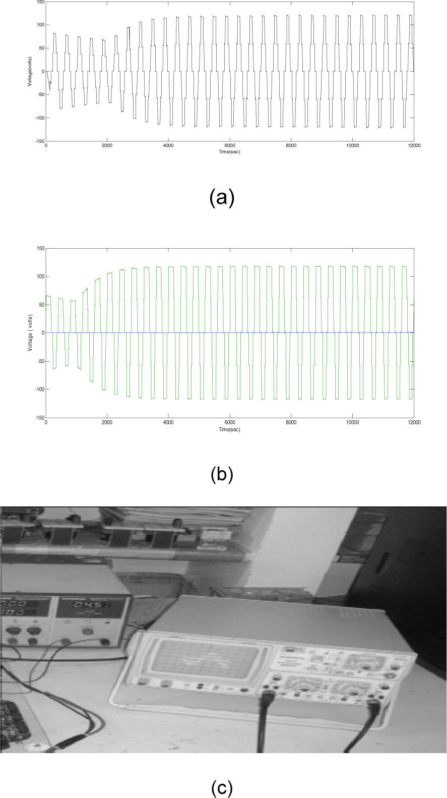
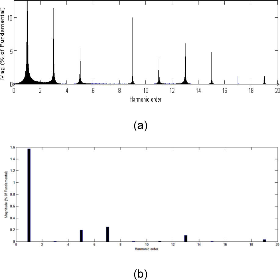
The multilevel Inverter was implemented with eight insulated gate bipolar transistor (IGBT) switches and internal antiparallel diodes for each switch. Four MOSFET high-speed high-voltage drivers were used to afford the gate signals to the power switches. A PIC microcontroller was used for firing pulse generation by the sinusoidal PWM and SHEPWM method. TOSHIBA 6N137 optocouplers were used to afford an isolation between the board and the power circuit. The ANFIS predicted modulation index and switching angles with third harmonic elimination in the five-level inverter were used experimentally. The simulated and experimental results of the output voltage in the five-level inverter can be observed as shown in Figure 10. In Figure 11, the results of the FFT harmonic analysis carried performed by the SPWM and SHEPWM method are presented.
 Simulation results of the SPWM method. (b) Simulation results of the SHEPWM method. (c) Experimental results")
 SPWM and (b) SHEPWM")
The selective third harmonic elimination PWM method in a cascaded H-bridge five-level inverter was observed to provide significant change in the percentage of THD compared to the sinusoidal PWM method. The use of the ANFIS method to estimate the modulation index and switching angles has been an additional advantage in claiming that the system provides better elimination of harmful third harmonics at the inverter output voltage. The feasibility of this technique is addressed and the results through the harmonic spectrum are compared, showing a significant difference. Results prove that the proposed method produces a fast and accurate response as well as minimum error compared to the NR method. Simulation and experimental results show that the proposed design of a cascaded H-bridge five-level inverter is a viable option for any stand-alone solar photovoltaic system with better output voltage.