


This paper considers an energy-efficient utilization in lighting control systems (LCS). A joint power and beam angle control in LCS is proposed that reduces energy consumption while satisfying the user’s lighting requirements. A problem to find the optimal pair of power and the beam angle of luminaries is formulated and an algorithm to find the optimal solution is suggested. The simulation results show that the proposed scheme achieves considerable improvement in energy savings compared to conventional lighting energy saving scheme which does not consider the beam angle control.
Energy efficiency has recently been receiving more and more attention for solving energy problems such as climate change and depletion of fossil fuels. It is said that almost a fifth of the total generated electricity is consumed for lighting and about 40% of total energy consumption for lighting is taken by office buildings [1, 2]. Therefore, lighting energy savings in buildings is recognized as an important issue for reduction of energy consumption.
A promising approach for saving lighting energy in buildings is LCS. LCSs are intelligent systems for efficient control of lighting composed of electrical devices such as motion/photo sensors and lighting controllers. An LCS is generally conjunctive with communication networks, where communication between devices is performed using machine-to-machine communication in a wired or wireless manner [3, 5]. IEEE 1451, IBECS (integrated building environmental communication system) and DALI (digital addressable lighting interface), are some of the standard protocols for communication between devices in LCS [6]. Wireless technologies have been considered a promising approach for LCS, which has the advantage of ease of installation and retrofitting. Researchers have attempted to replace the traditional ceiling-mounted photosensors with wireless sensors network, which results in similar or even high energy saving than traditional systems [7, 8]. By monitoring current light illuminance and user occupancy, an LCS controls lighting devices to provide sufficient lighting quality for indoor users, and energy-efficient lighting control algorithms for LCS have been receiving more attention, being regarded as a key technology for saving energy.
Recently there have been some works on lighting control algorithms in LCS to improve the energy efficiency of LCS while satisfying lighting requirements of the users. Meng-Shiuan et al. presented an LCS based on wireless sensor networks considering user activities and profiles, this scheme considers two kind of light devices, namely, whole lighting and local lighting devices, and two kind of sensors, namely fixed and portable sensors [9, 10]. Carrying portable sensors is not convenient in practical applications, also specifying current activities via portable sensors and controlling local lighting devices that can be controlled by the user locally increase the complexity of the proposed system. Ono et al. presented a lighting power control algorithm that provides the user-required illuminance levels while minimizing power consumption of the luminaires [11]. Hiroyasu et al. optimized the illuminance distribution control using steepest-descent technique to minimize the difference between current illuminance and required illuminance level [12]. A lighting power optimization algorithm has also been proposed based on a linear programming (LP) problem that minimizes the total power of the luminaires while satisfying the user’s requirements [13].
Lighting control algorithms in previous works can be effective in saving power by properly controlling illuminance or the power consumed by luminaires. However, a more efficient lighting control scheme can be developed if additional control parameters are considered. Considering that the beam angle of a luminaire can be adjusted by moving the reflector [14], this paper proposes joint power and beam angle control for enhanced lighting energy efficiency of an LCS. An optimization problem is formulated to minimize the total luminous flux of luminaires, and an algorithm to solve the optimization problem is suggested. The performance evaluation results show that the proposed scheme achieves improvement in power savings.
The rest of the paper is organized as follows. Section 2 introduces the system model. Section 3 presents the formulation of the optimization problem and the proposed algorithm for computing optimal power and beam angle. Section 4 presents the performance evaluation results of the proposed scheme. Finally, Section 5 concludes this paper.
2System modelThis paper considers an LCS in a room as shown in Figure 1. It is assumed that L identical luminaries are equally spaced on the ceiling of a room, while the floor is geographically divided into J identical squares grids (or “work places”). A zoning strategy is used to group grids into different zones base on identical illuminance requirements. Figure 2 shows a zoning strategy for a typical share office. The squires of the floor are grouped into three zones. Zone A consists of the grids where high illuminance is required for activities like reading or working on the computer, where zone B consists of grids at the center area of the office where the illuminance requirements is usually low, and zone C consists of grids located near the door of the office. A central control unit (CCU) communicates with a luminaire controller (LC) and sensors using wireless network. The CCU gathers environmental information such as current illuminance level, occupancy data, and the required illuminance level from sensors or a user input device. Users are considered to have different illumination requirements according to their activities. The proper values for power and beam width of each luminaire are computed based on the information. The selected power and beam width information are sent to the LC, and the LC controls the power and beam width of each luminaire based on the information [15]. It is assumed that the information is collected and exchanged between different devices without any error and delay.


The energy (w) spent in illuminating the room can be computed as

where pi and ti are the input power and operating time (hour) of luminaire i, respectively. This input power Pi produces luminous flux (fi). Let the illuminance level at work place j from all luminaires be denoted by Lj, which can be computed by aggregating illuminance from each luminaire. Then Lj is represented by

where lij is the illuminance level at work place j from luminaire i, which is modeled as
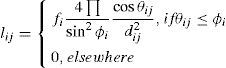
where ϕi is the beam angle of luminaire i [16, 17]. θij is the angle between the normal to the work place j and the direction of the luminaire i, and dij is the distance between the work place j and the luminaire i. Let Ljr denote the required illuminance level for work space j, which must be guaranteed to be at the center of the corresponding work place. A set of discrete values of φi’s and a limited range of continuous fi’s values that are proportional to the input luminaire power are assumed [18, 19]. Then, an issue of resource control in the LCS to find an optimal pair of fi᾽s values and φi’s values for efficient LCS operation arises, with an objective of minimizing the total power consumption of luminaires while providing the required illuminance level at each work place.
3Proposed joint power and beam angle control scheme3.1Problem formulationThe objective of joint power and beam angle control is to minimize the total power consumption of luminaires with constraints of user satisfaction and limited range of control parameters. With an assumption that luminous flux is proportional to power, the objective can be changed by minimizing the total flux of the luminaires. Then, an optimization problem P0 for efficient control of the luminaires is presented as
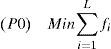

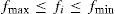

where fmin and fmax are the minimum and maximum dimming capabilities, and Φ is the set of available beam angles values. Equation 4 is the objective function to minimize the sum flux of luminaires, and Equation 5 shows the constraints for provision of the required illuminance level at each work place. Equations 6 and 7 limit the range of flux and beam angle of each luminary, respectively. For given φi’s, values, P0 is a linear program (LP) problem for fi’s, which is represented as
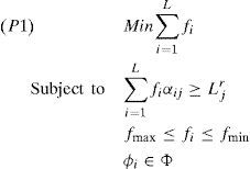
where ∝ijreplaces (4πcos θij)/(dij2 sin2φi).
3.2AlgorithmTo solve the lighting control optimization problem, an algorithm is suggested that uses a full search followed by an LP problem. The full search is used to generate unique combinations of discrete φi’s, and, in this way, a total of T unique combinations are generated, where T=ML, and M denote the number of discrete values of φi’s. At each iteration of full search, P1 is solved for given φi’s using a CVX tool to obtain the optimal values. Let the optimal fi’s and the corresponding φi’s for the kth iteration be denoted by fi*(k)’ s and φi*(k)’s, respectively. Thus, a total of T fi*(k)’ s are obtained, among which the fi*(k)’ s with minimum summation and the corresponding φi*(k)’ s are chosen as the optimal solution. This process is summarized in the algorithm below:
Algorithm
Πk : Summation of fi*(k)’ s for (i=1 to L) fi
fi* : Optimal luminous flux of ith luminaire
φi*: Optimal beam angle of ith luminaire
Ω: Iteration Index of optimal solution
Ψ: Minimum Πk
Begin
- 1:
Ψ=L ⋅fmax
- 2:
For k=1 to M
- 3:
Generate combination of φi’s, (i=1 toL)
- 4:
Solve P1 using CVX to obtain fi*, (i=1 toL)
cvx_begin
variablefi (L, 1)
minimize (∑i=1 Lfi)
Subject to
Li>= Lir
fi > fmin
fi <= fmax
cvx_end
- 5:
If Πk < ΨThen
- 6:
Update Ψ and Ω
Ψ=Πk
Ω=k
EndIf
EndFor
- 7:
For i=1 to L
fi*=fi*(Ω)
φi*=φi*(Ω)
EndFor
End
This section provides the performance evaluation of the proposed joint power and beam angle control scheme in comparison with a conventional lighting control scheme by a measure of total luminous flux.
A light power control scheme with fixed beam angle is considered as the conventional scheme.
An LCS is considered for a 5m×5m×4m cubic room. The room is divided into 25 regions of space, each of size 1m×1m. Four luminaries are considered to be located on the ceiling. The maximum luminous flux of each luminaire is considered to be 5000lm. Two recommended illuminance levels of 200lx and 400lx for normal activities are assumed as the required illuminance levels [20]. The occupants were placed in the square grids in a random manner. It is assumed that Φ consists of discrete values of beam angle that can be described as φi=Δ×n such that (0°<φi≤90°), where n is a positive integer, and Δ is the unit step size of the beam angle control. For example, Φ consists of discrete beam angles of 20°, 40°, 60° and 80° for a unit step size of 20°.
Figure 3 compares the luminous flux of four luminaires for user occupancy rate of 20%, 40%, 60%, 80%, and 100%, of the proposed scheme and conventional scheme. The proposed scheme adjusts the beam angle of luminaires at the optimal beam angles that satisfy the required illuminance level at each workplace and minimizes the sum of luminous flux of all luminaries. The luminous flux of some luminaires can be smaller in case of a conventional scheme as compared to the proposed scheme at a certain occupancy valve, but the sum of luminous flux of all luminaires is always minimum

In the case of the proposed scheme. In other words, the proposed scheme minimizes the total luminous flux of the luminaires.
Figure 4 compares the total luminous flux of the proposed scheme and the conventional scheme for user occupancy rates of 4~100% unit step size of 20°. The simulations were carried out for 500 iterations; occupants were distributed randomly at each iteration. The average of total luminous flux is computed for comparison. The proposed scheme reduces the total luminous flux of the luminaires and achieves 25% average improvement in lighting energy savings. It is observed that the total luminous flux increases with the increase of user occupancy rate, as well as with the user required illuminance level.

Figure 5 compares the total luminous fluxes of the proposed and conventional schemes for various unit step sizes of 5°, 10°, 15° and 20°, where the user required illuminance level is 200lx. The proposed scheme achieves energy savings of 15% on average at various unit step sizes, as shown in Figure 5. It is noted that energy saving in the proposed scheme can be improved by using small Δ.
5Conclusion
This paper proposed a lighting beam angle control scheme that efficiently minimizes the energy consumption of a lighting system while satisfying the user’s lighting requirements. The simulation results show that the proposed scheme can increase energy savings by up to 25% on average compared to the conventional scheme. To further enhance the energy efficiency of LCS, a joint blind angle control for efficient utilization of available daylight will be considered in future works.
This work was supported by the Basic Science Research Program through the National Research Foundation of Korea (NRF) funded by the Ministry of Education, Science and Technology (2011-0005439).