


This paper describes the integration and implementation of a satellite flight simulator based on an air bearing system, which was designed and instrumented in our laboratory to evaluate and to perform research in the field of Attitude Determination and Control Systems for satellites, using the hardware-in-the-loop technique. The satellite flight simulator considers two main blocks: an instrumented mobile platform and an external computer executing costume-made Matlab® software. The first block is an air bearing system containing an FPGA based on-board computer with capabilities to integrate digital architectures for data acquisition from inertial navigation sensors, control of actuators and communications data handling. The second block is an external personal computer, which runs in parallel Matlab® based algorithms for attitude determination and control. Both blocks are linked by means of radio modems. The paper also presents the analysis of the satellite flight simulator dynamics in order to obtain its movement equation which allows a better understanding of the satellite flight simulator behavior. In addition, the paper shows experimental results about the automated tracking of the satellite flight simulator based a virtual reality model developed in Matlab®. It also depicts two different versions of FPGA based on-board computers developed in-house to integrate embedded and polymorphic digital architectures for spacecrafts applications. Finally, the paper shows successful experimental results for an attitude control test using the satellite flight simulator based on a linear control law.
En este artículo se describe la integración e implementación de un simulador de vuelo satelital basado en un sistema de cojinete de aire, el cual fue diseñado e instrumentado en nuestro laboratorio para realizar investigación en el campo de sistemas de control de actitud de satélites, utilizando la técnica hardware-in-the-loop. El simulador de vuelo satelital cuenta con dos bloques principales: una plataforma móvil y una computadora externa donde se ejecuta software desarrollado en Matlab®. El primer bloque, integrado en una plataforma móvil suspendida en aire, contiene una computadora abordo basada en un dispositivo FPGA con capacidad de integrar arquitecturas digitales para adquisición de datos de sensores de navegación inercial, control de actuadores y manejo de datos. El segundo bloque es una computadora personal, donde en paralelo se ejecutan algoritmos basados en funciones desarrolladas en Matlab® para la determinación y el control de actitud. Ambos bloques están unidos inalámbricamente. En este artículo se presenta también el análisis de la dinámica de simulador de vuelo satelital para obtener su ecuación de movimiento, que permite una mejor comprensión del comportamiento del simulador. Además, se muestran los resultados experimentales de seguimiento automatizado del simulador de vuelo satelital basado en un modelo de realidad virtual. Se describe también el desarrollo de dos versiones de computadoras abordo basadas en FPGA para integrar arquitecturas digitales embebidas para aplicaciones en vehículos espaciales. Por último, el artículo muestra resultados experimentales de pruebas de control de actitud utilizando el simulador de vuelo satelital basada en una ley de control lineal.
The Attitude Determination and Control System (ADCS) is a core module of a satellite platform, whose main function is to ensure the spacecraft will be pointing towards required targets either in earth or in space. When a satellite is placed in space orbit, and depending on its orbital altitude, it is subject to a number of environmental perturbations which deflect it from the desired orientation. In the case of Low Earth Orbit, located within 1000 km altitude, some of these disturbances are: atmospheric drag, the interaction with the Earth’s gravitational field or nearby bodies in space, pressure due to solar radiation, among others [1].
An ADCS has all necessary hardware and software resources to compensate the deviations caused by such disruptive forces by applying control torques to the spacecraft, as well as with the execution of correction maneuvers based on data obtained from inertial navigation sensors. In this way, the satellite will point toward required targets [2]. The process of design and implementation of a satellite ADCS, involves the selection and sizing of equipment and components for the ADCS (navigation sensors, computing platform and actuators), as well as the definition of algorithms for attitude determination and control [2].
This approach also allows the development of simulators for validation of attitude control schemes [3], [4], [5], [25] which in our case are employed as test bench for physical validation of ADCS for spacecrafts in laboratory. Accordingly, the approach considers the attitude hardware selection processes (navigation sensors, actuators and on-board computer) and the definition of attitude control algorithms (determination, estimation and control laws). In this way, the research work presented in this paper allowed the experimentation and development of different components of the system. The approach has prompted the creation of a simulator not only for use in the definition stage of ADCS components (hardware and software), but also in the integration of an experimental test bed platform to conduct applied research in the field of spacecrafts attitude control. In addition, has allowed the formation of human resources in our laboratory in the referred field.
Moreover, this paper describes the integration and development of a Satellite Flight Simulator (SFS) developed at the Aerospace Development Laboratory at the Instituto de Ingeniería, UNAM (IINGEN-UNAM). Details about dynamic modeling, experimental results, testing and realtime monitoring of the SFS are also presented. The latter derived from the implementation of a particular case of control based on a linear sketch, using a hardware-in-the-loop (HIL) co-simulation scheme to accelerate the development process to obtain experimental results. From compact and modularized architecture, the SFS allowed to develop University technology and research in the area of attitude control, for satellites as well as for training purposes in areas such as: control, instrumentation, software development, electronics, telecommunications, and mechanical design.
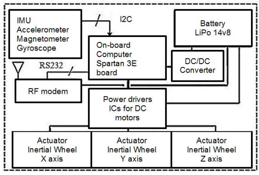
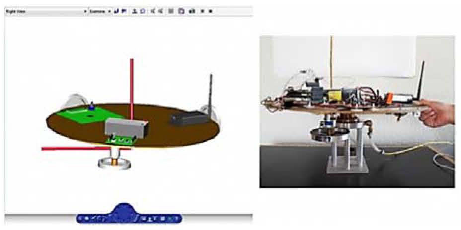
2Implementation Overview of the SFS simulation platformThe SFS was fully developed and instrumented at IINGEN-UNAM. It employs air flows generated with a compressor to levitate an instrumented platform that emulates the frictionless environment from space. On the platform side was installed the same scheme of implementation corresponding to a real satellite ADCS, thus, integrating inertial navigation sensors, flight computer, active actuators based on inertial wheels, communications, power and other electronic components of support, figure 1.

The SFS integrates an open and flexible electronic instrumentation architecture in software and hardware. In addition, the SFS platform performs 360° rotational maneuvers in yaw and 20° maneuvers in pitch and roll. Its main goal is to accomplish a test bed for applied R&D in the field of satellite attitude control strategies in software and hardware. In this regard, the SFS can be equipped with different types of sensors, actuators, on-board computers (MCU, FPGA or DSP) and algorithms in order to validate new instrumentation architectures or data processing schemes for space applications [6].
3SFS Hardware implementation under an HIL schemeThe SFS hardware was developed in two main blocks around an HIL instrumentation scheme, the first one is an instrumented mobile platform, while the second one is an external PC running Matlab® software.
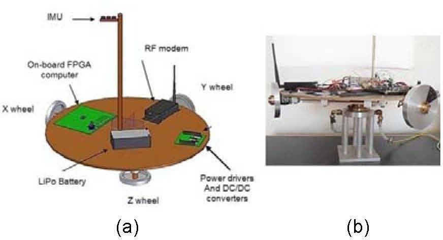
3.1SFS mobile platformThe circular shape of the SFS platform, figure 2(a), was manufactured with Medium Density Fiberboard material with ρrelative = 0.7, 50 cm in diameter and 1 cm thick, figure 2(b). The mobile platform is attached to a mechanical semi-sphere forming the air bearing against a fixed metallic base. The fixed base is 30 cm in height and its surface is perforated by 6 pipelines through which airflows run to levitate the SFS platform, creating the frictionless effect.
 SFS Model developed in Solid Works software, b) SFS experimental implementation.")
The SFS air cushion is created by a steady flow provided by a compressor operating at levels of 60 to 70 psi. This flow is fed to a bank of filters (coalescing and desiccant) to remove traces of fuel and water, thereby preventing clogging of milimetric capillary ducts located at the base of the SFS support [6].
Besides, the SFS platform contains the attitude control hardware, grouped into 6 main segments: inertial navigation sensors, on-board computer, actuators, power drivers, power supply and communications.
3.1.1SFS inertial navigation sensorsThe Sparkfun® SEN-10724 Inertial Measurement Unit (IMU) is a small card that delivers nine measures. It includes three MEM technology three axis navigation sensors: an HMC5883L magnetometer with 12 bits resolution, an ADXL345 accelerometer with 16 bits resolution, and an ITG3200 gyroscope with 10 bits resolution; all them share the I2C communication protocol.
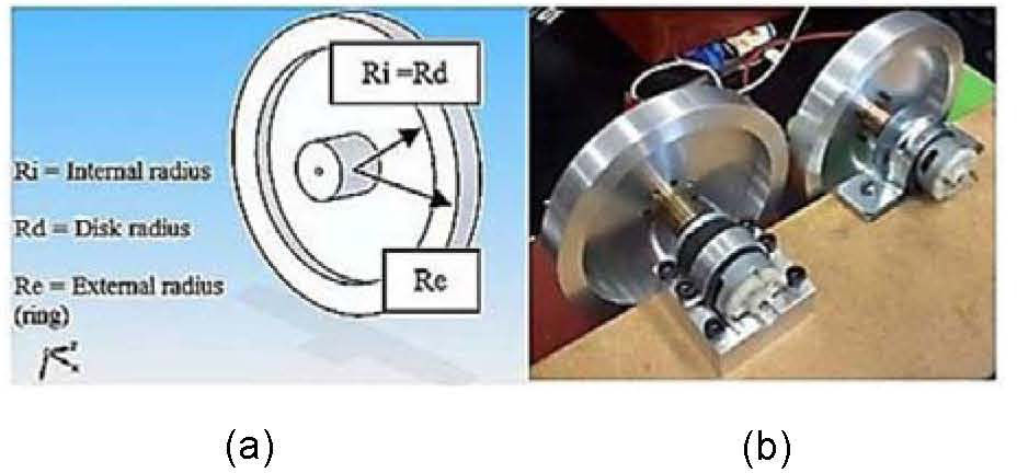
3.1.2SFS inertial wheelsThe design of actuators considered the onboard mass distribution of the SFS platform. While the design process took the decision to employ a set of 3 inertial wheels with aluminum disks as shown in figure 3(a). Every disk has an outer ring that maximizes the momentum of inertia provided by the wheel in order to guarantee attitude control maneuvers of the SFS platform [7].
 Model developed in Solid Edge ® software, b) prototypes developed at IINGEN-UNAM.")
Each actuator uses a 12 V DC brushed motor and a 7076 type aluminum inertial wheel, figure 3(b). The wheels have a diameter of 10.8 cm, a mass close to 250 g and are orthogonally installed in the SFS platform according to an inertial reference system with origin at the geometric center of the SFS. More details about the inertial wheels design are available in [7].
3.1.3SFS on-board computersThe SFS automation process regarded the use of several on-board computers. The first one was a commercial available Spartan 3E-Starter Kit from Xilinx®. The second one was a computer based on the XC3S100E FPGA with 100,000 logic gates developed in-house. The third one was also developed in-house and is about to be manufactured in our laboratory; this enhanced computer is based in the XC3S1600E FPGA from Xilinx® with 1,600,000 equivalent logic gates.
3.1.3.1Spartan 3E FPGA based on-board computerThe first on-board computer employed in the SFS was embedded into a Xilinx ® Spartan-3E Starter Kit (SP3E) commercial development system. This commercial platform allowed implanting several digital embedded computing architectures to shape the data acquisition and control commands generation modules for the SFS actuators.
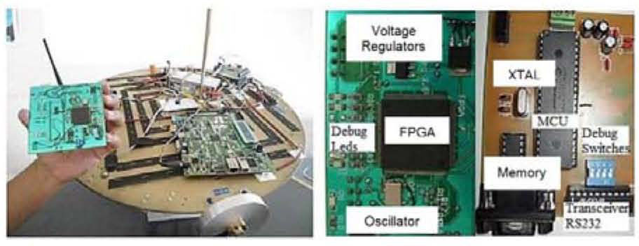
3.1.3.2First FPGA based on-board computer developed in-houseBased on the specific technical requirements of logical interfaces, digital inputs and outputs, as well as debugging and testing resources to validate digital architectures into the Spartan 3E platform; it was designed and built a self-developed system based on an FPGA. The system called SMIN-V1 is integrated by two segments: software for ground station and an electronic board, figure 4. The ground station software allows the user to remotely send the file containing the FPGA reconfiguration data, and manage the processes of reading and writing the memory board. Moreover it allows verifying the contents of memory board, which stores delivered data, and the opening and closing communication ports of a host computer.

Meanwhile the electronic board, was implemented at IINGEN-UNAM, [8], [9], and [10] on a double-sided printed circuit board of 10 × 10 cm, whose central component is an XC3S100E FPGA from Xilinx®, it contains the resources needed for experimental validation of attitude control strategies, interacting with instrumentation aboard the MSA, mainly with inertial navigation sensors and actuators. Additionally, the SMIN-V1 board integrates a remote reconfiguration module, which through a microcontroller (MCU) allows, in runtime, updating the integrated digital architectures into the SMIN-V1 board to provide solutions to other attitude control schemes required in the SFS [11].
The design of the electronic board SMIN-V1, includes not only the experimental implementation of the control logic of a single subsystem, but also has the flexibility needed to accommodate the logic of another subsystems of a spacecraft using the same hardware structure. This is an advantage in terms of saving space and resources optimization for design and integration of small satellites.
3.1.3.3Second FPGA based on-board computer developed in-houseCurrently, the second generation of FPGA based computer named SMIN-V2 for the SFS is about to be manufactured and tested at IINGEN-UNAM. This new computer, with similar characteristics to the SMIN-V1, includes a bigger FPGA device, the XC3S1600E, allowing the integration of more complex computer architectures and embedded systems. It also includes more digital I/Os and a bigger memory bank based on FLASH technology, to store the reconfiguration bitstream among other improvements on hardware.
3.1.4SFS Radio frequency modemsThe wireless link that enables data transfer at a distance of up to 450 meters between the SFS platform and a PC is established through two XStream-PKG-R RF modems operating at 900 MHz with 100 mW of power. The radios use the RS232 protocol, which facilitates their interaction with computers for sending and receiving data and control commands.
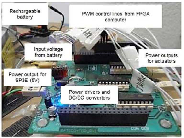
3.1.5SFS Actuator Power Drivers (APD)The APD and power system modules for the SFS resides in a printed circuit board (PCB), designed and developed in-house. The PCB contains three L6202 integrated circuits for managing power to the actuators and a DC / DC converter to feed the required voltage to the SP3E board.
The L6202 drivers apply power to every DC motor from three actuators placed in three axes at the SFS platform (x, y, z), according with control commands generated by the on-board computer.
The power module consists of a Thunder Power RC LiPo (Lithium Polymer) 7700 mAh rechargeable battery with 4 cells, 14.8 V output and a DC / DC converter.
The DC / DC converter is an LM2575 integrated circuit, which is a step-down type voltage regulator that provides an output voltage of 5V at 1A, with a maximum input of 45V. Figure 5 shows the power board aboard the SFS platform, emphasizing that the battery is connected to this board.
3.2SFS external PC running Matlab® software
The SFS employs an external PC with a set of functions in Matlab® developed from interconnected scripts aiming the processing of data blocks sent from the SFS platform. This processing is related to algorithms for attitude control, such as TRIAD, EKF and CONTROL algorithms. Details about this are given in a later section.
4Dynamics Analysis of the SFSAt IINGEN-UNAM we are very interested in having a better understanding of the SFS behavior. In this regard, strong efforts have been made in the theoretical side to develop the dynamics analysis of the SFS aiming in the near future to develop satellite attitude control solutions strictly based in theoretical research.
From this point of view our group would have the possibilities to generate attitude control solutions for satellites either by experimental or by theoretical means.
In addition, we would have the skills to generate hybrid solutions. Therefore in this section the dynamics analysis elaborated for the SFS is presented.The dynamics analysis performed to the SFS platform considers that it is integrated by four rigid bodies: a mobile platform and three inertial wheels.
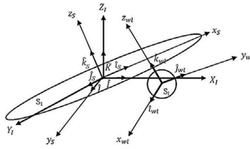
These elements are rigidly attached to each other and have three rotational degrees of freedom. In addition, the analysis includes a mobile reference system and an inertial reference system for the whole system, figure 6, [14], defined as follow:
- 1.-
Orthonormal system (Iˆ,Jˆ,Kˆ): corresponds to the inertial reference system whose origin matches with the geometric center of SFS mobile platform and its principal axes 0XI YI ZI.
- 2.-
Orthonormal system (iˆS, jˆS, kˆS): corresponds to the moving reference system that is fixed to the SFS platform.
- 3.-
Orthonormal system (iˆwl, jˆwl, kˆwl) corresponds to the mobile reference system that z.

In addition, figure 6 shows the following details:
▪OXI YI ZI is the inertial reference system
▪Iˆ, Jˆ, Kˆ are orthogonal vectors of the inertial reference system
▪OxSySzS is the mobile system
▪iˆ, jˆ, kˆ are orthogonal vectors of the mobile system
▪S1 is the SFS mobile platform
▪SI is anyone of 3 SFS inertial wheels
l = 1,2,3 correspond to each inertial wheel installed on the platform.
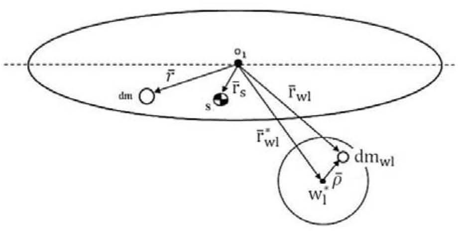
Besides, figure 7 shows the vector relationship between the inertial platform and wheels, relative to an inertial reference system. In the following section an analysis is presented for a single inertial wheel, while the analysis for the remaining inertial wheels is analogous.

From figure 7 the following definitions are established:
O1 geometric center of SFS platform
S the center of mass of SFS platform
dm differential mass of SFS platform
dmwl differential mass of inertial wheel
r¯wl position vector from the geometric center O1 of the SFS platform to the differential mass dmwl of the inertial wheel.
wl* center of mass of the inertial wheel.
r¯wl* resultant vector subtended from the geometric center O1 of the SFS platform to the center of mass of the inertial wheel.
ρ¯ position vector subtended from the center of mass of the inertial wheel to a differential mass dm of the wheel itself.
r¯ position vector subtended from the geometric center of the SFS platform to the differential mass dm of the platform.
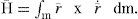
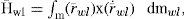
4.1SFS Kinematic modelingTo describe the angular momentum H― of SFS, it is considered the S platform and the three inertial wheels as a set of four bodies with a common point Ok, where k = 1,2,3,4, and O1 corresponds to the fixed point of the system.
In addition, it is defined the angular velocity ω¯k and the absolute velocity v¯k regarding Ok. The analysis for the SFS system starts with Eq. (1) [12]
In addition, r¯˙ is given by the first derivative obtained from r¯, so we have,

where ω¯IS is the angular velocity of the platform relative to the inertial reference system.
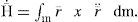
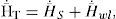
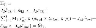
From Eq. (1), we consider the angular momentum H― of the SFS, which is determined by analysis of the S platform and the Sl inertial wheels. Then, the total angular momentum of the SFS H¯T is defined as

where H¯wl is the angular momentum of inertial wheels. Substituting Eq. (2) in (1) and solving the integral, we have,

where
MS is the total mass of the platform and Js correspond to the inertia tensor of the platform.
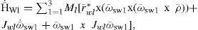
Furthermore, the angular momentum of inertial wheels H¯wl can be written as
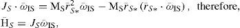
where r¯wl=r¯wl∗+ρ¯ and r¯˙wl=ω¯IS x r¯wl∗+ω¯swl x ρ¯, considering ω¯swl as the angular velocity of the wheel relative to the platform. Substituting r¯wl and r¯˙wl in terms of their respective position vectors, as shown in figure 7, and solving the integral, the following result is obtained

where l = 1, 2, 3 correspond to the number of inertial wheels mounted on the SFS platform and Mwl corresponds to the mass of the inertial wheels. Then, from Eqs. (3), (5) and (7), the total angular momentum of the SFS platform is

where JS, is the inertia tensor of the mobile platform, while Jwl* and Jwl are the inertia tensors of the inertial wheel.
4.1.1SFS Dynamic modeling and the system equation of motionIt is highlighted that the SFS platform is referred to the inertial system (I) and the inertial wheels are referred to the air bearing system platform.
Using the theorem ddtH¯=M, [12], [13] where M is the momentum of force, it is assumed that the SFS platform movement is constrained to rotational motion around the inertial reference frame, whose origin coincides with the geometric center of the platform, as shown in figure 7, [15] [16].
Obtaining the derivative with respect to time of the angular momentum at a fixed point O1 which is an equivalent force upon the system, Eq. (9) is generated [12]
For the SFS platform, it is assumed that the total torque H¯˙T will result from the contribution of torques from both platform H¯˙S and inertial wheels H¯˙wl. So, applying the principle of conservation, the next expression (10) is obtained
substituting and solving for the SFS platform, we have,

Solving for the inertial wheels H¯˙wl, we obtain,


Substituting Eqs. (12) and (13) into Eq. (9) and solving the integrals, we have,
substituting Eqs. (14) and (11) into (10), we have,
where M―T are the total momentums that disturb the stability of the SFS mobile platform. Then, we obtain the total momentums M―T from the contribution of the external torques M―FEX and internal torques M¯IN, as outlined in Eq. (16)
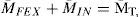
whereas the system is rigid, then M¯IN=0 and then the only external force is given by
Substituting Eq. (17) into (15), we have:
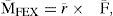
It will be considered that the only external disturbance (MFEX) that affects the system is the Earth’s gravitational force, so,

where γ is the unit vector perpendicular to the center of the earth (gravitational force).
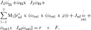
Substituting Eq. (19) into (18) we obtain the Eq. of motion (dynamic) for the SFS
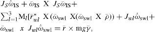
where MS is the total mass of the SFS platform and Ml, is the total mass of the inertial wheels. This Eq. of motion will be used to forecast the analytical behavior of the SFS, as explained in next sections.
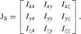
4.1.2SFS Inertial tensorsFor the case of the SFS mobile platform, JS is the inertia tensor, defined as:
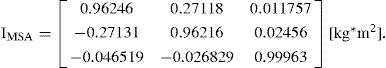
On the other hand, the inertia tensor of the instrumented SFS platform calculated with CAD software (Solid Works®), figure 3, and considered from the center of mass, is
For the case of the inertial wheel, the calculated inertia tensors Jwl were obtained with Solid Edge, figure 3a, they have the following form:
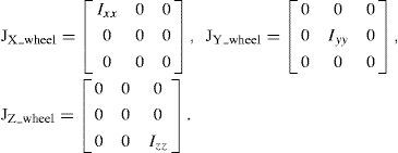
Each component of the matrix corresponds to the momentums of inertia about each one of the main SFS platform axes, which are: Ixx = Iyy = Izz =0.0038 kg *m2.
4.1.3Research approach for satellite attitude control through the SFS equation of motionThe Eq. (20), describing the SFS motion, was used in our laboratory to implement a system tracking by means of Matlab® virtual reality models.
This supporting tool is useful when performing automated attitude control tests with the SFS, complementing the experimental slope with analytical and theoretical approach, allowing understanding the details in the attitude control maneuvers with the simulator platform, figure 9.

For the case of analytical side, further work has to be made in order to accomplish a full modeling environment, where the experimental SFS will be replaced by full digital models about inertial navigation sensors, actuators and disturbances.
Particularly from the equation of motion (20) is feasible to set the equation projections to three principal axes (X, Y, Z) from the SFS platform, relative to its inertial reference frame, using quaternions as a form of representation of the orientation. Afterwards, a linearization process would be required in order to accomplish a model with equations of state, [16] and [17]. After this, controllability and stability analysis would be made to develop attitude controllers for satellite applications, all this by theoretical means. Therefore, this research approach would allow developing fully theoretical research regarding satellite attitude control strategies. Further results about this approach will be published in future papers.
4.2Tracking experiment of the SFS employing a virtual reality modelBased in the motion description model of the SFS, described in Section 4.1, we implemented the SFS tracking system through the use of an SFS CAD model developed into a virtual reality environment [18]. The study considered the management of both the mobile and inertial reference frames as well as the representation of rigid body orientation using unit quaternions. The virtual model regarded physical features of SFS (21) and (22), while it allowed to validate a first scheme of interacting software in real time with SFS attitude hardware (inertial navigation sensors and FPGA). Figure 8 describes a global view of the experiment.

The scheme used for attitude determination is contained within an integrated simulation model based in TRIAD algorithm [19], which uses blocks defined in Simulink®. Particularly, the TRIAD algorithm determines the rotation matrix of two coordinate systems. The first one is the inertial reference system that is associated with predefined reference vectors for each one of the navigation sensors (magnetometer and accelerometer). The second one is formed from mobile vectors generated from each navigation sensor on the SFS platform. To optimize the data processing for the rotation matrix obtained with the TRIAD technique, a transformation was performed to unit quaternions [20].
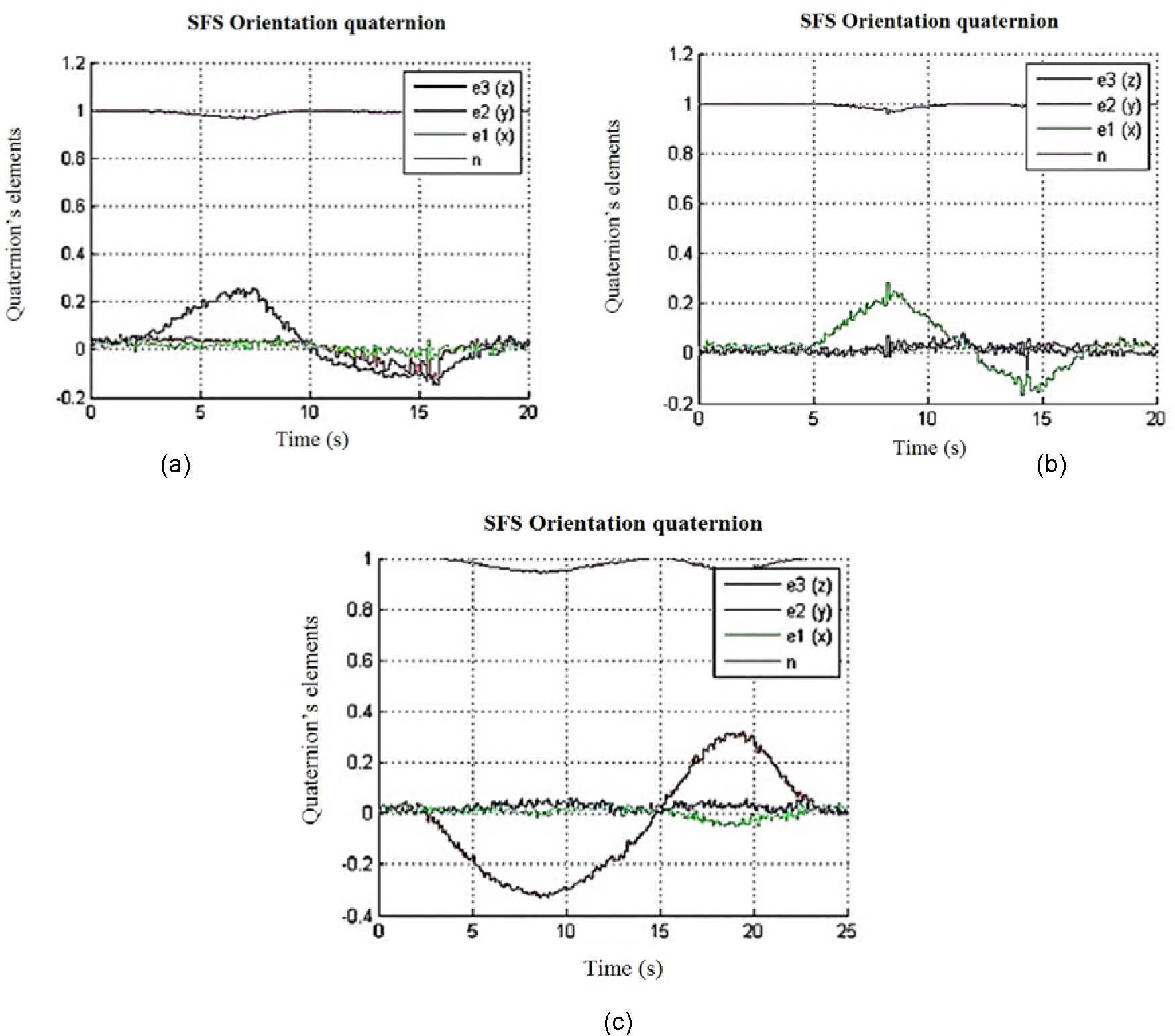
Based on the block model described in figure 8, experiments were performed manually to move the SFS platform with an angular displacement of 45 ° from each of its three main axes (X, Y, Z). Figure 9 shows the tracking action of the virtual reality model with respect /to the frictionless movements of the SFS platform.
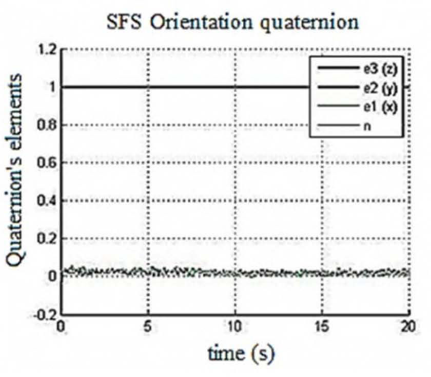
4.2.1Successful results regarding SFS virtual reality trackingConsidering the zero position described by the unit quaternion q = [1 0 0 0], figure 10, according with the notation q=n e¯1 e¯2 e¯3, where n is the scalar part, and e¯1, e¯2ande¯3 are the vector part of the quaternion. Figures 11 a), 11 b) and 11 c) show graphs of q elements for tracking experiments of a 45° maneuver of the SFS platform around each one of the X, Y and Z axis.

 X, b) Y, c) Z.")
During these tests the SFS was manually maneuvered by the user around the respective reference frame (mobile reference frame fixed to the SFS) and the automated tracking was generated by the Simulink® model which renders high quality 3-D animations.
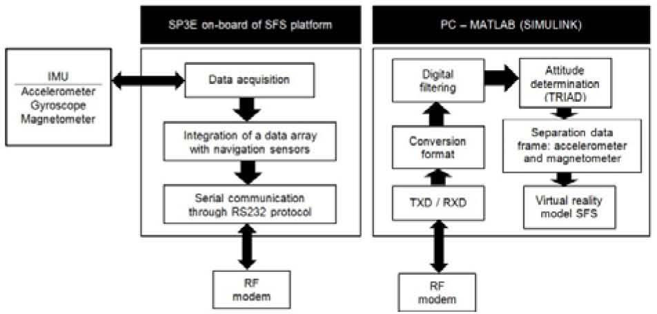
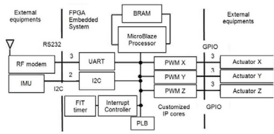
5Implementation of an attitude control scheme with the SFS platformA computer architecture was embedded into the aboard FPGA, it contains an embedded MicroBlaze (MB) microprocessor [24], figure 12. This computer performs the tasks of data acquisition (through I2C protocol) using a Fixed Interval Timer within an interruption scheme as well as data communications handling from navigation sensors, which are sent to the PC through the UART module contained in the MB. The on board computer also decodes the control commands sent from the PC (8 bits to define Pulse Width Modulation (PWM) duty cycle and 1 bit to establish wheel direction) and generates digital control commands for each actuator [6].

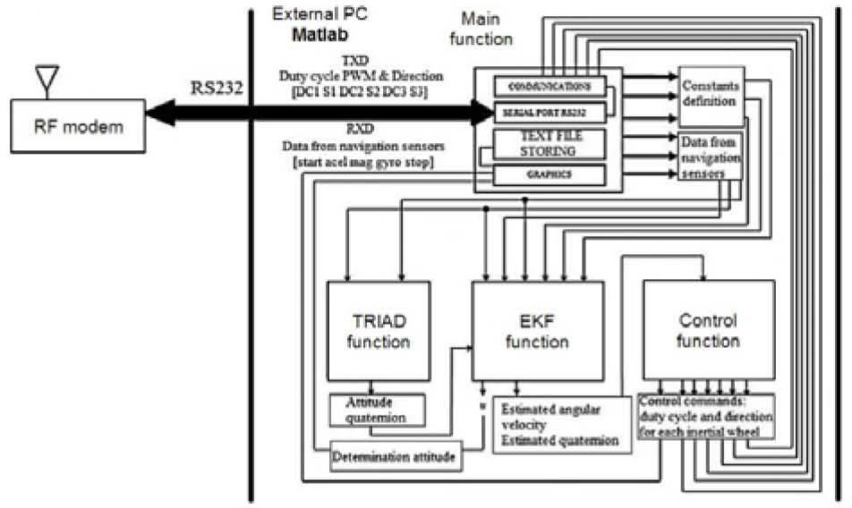
On the PC side as indicated in section 3.2, there is a set of functions in Matlab® whose task is focused on the processing of data blocks sent from the SFS platform. They are coupled with algorithms TRIAD, EKF and CONTROL for attitude control. Figure 13 shows the whole system of functions developed in Matlab® for this simulator.

The modular architecture of system functions, shown in figure 13, was successfully integrated, allowing the evaluation of different satellite automation schemes such as: attitude determination, estimation and control.
An important feature of the system functions, described in figure 13, is the distribution of data from navigation sensors integrated into the array [acel gyro mag].
It was implemented in the main function, where also is found the configuration and control of the RS232 port and the corresponding data storage for each test in text files, for later graphing and discussion about results of attitude control tests with the SFS [6].
The evaluation tests to control the SFS platform were made through graphs. The study starts with the quaternions components (measured and estimated), which can lead to necessary adjustment of parameters associated with logic of the TRIAD and Extended Kalman Filter (EKF) algorithms (reference sensors data, desired position, covariance of processes and sensors) as well as with gains of drivers regarding the SFS control module.
6Example of algorithm validation for SFS attitude controlThe control scheme used in the test corresponds to an attitude control strategy in three axes, [21] and [22]. This algorithm can lead the satellite (represented by the SFS platform) to a desired orientation when full data set is available to determine the satellite’s attitude. In this case using unit quaternions obtained from the EKF.
The EKF provides information regarding orientation, estimation as well as signal filtering of the satellite orientation [23] based on inertial navigation sensors such as magnetometers, gyroscopes and accelerometers, them all in three axis.
The controller corresponds to a proportional-derivative type, as stated in Eq. (23)

where:
- •
τcontrol represents the control torque to be applied to any one of the three actuators.
- •
kp and kd are gains of proportional and derivative controllers respectively.
- •
∊ˆ corresponds to the vector of the estimated quaternion.
- •
Ω represents the estimated angular velocity.
Then, according with Eq. (24), the resultant control torque of the Eq. (23) is converted to a percentage of PWM duty cycle coded from 0 to 256 in 8 bits adding one sign bit for every one of the three inertial wheels installed on the X, Y and Z axis [6]

where:
- •
τcontrol is an array containing the control torque of the three components (X, Y, Z).
- •
τmaxDCmotor is the maximum torque of the DC motor used in the actuator, in a respective axis. Particularly, SFS has a torque value of 0.07 Nm.
While byte_IP_PWM is the digital word written to the intellectual _ property (IP) core PWM on the FPGA, encoded in 8 bits, which represents the percentage of duty cycle, and defined according with Eq. (25)
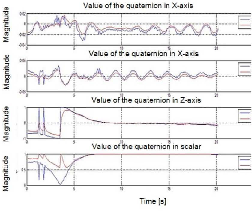
Figure 14 shows the behavior of each one of the four components of a standard quaternion in a lapse of time of 25 seconds in an experimental test of SFS attitude control. The graphs allow to evaluate the performance of the SFS during the development of maneuvers in each one of the axes (X, Y, Z), which allowed to move the platform from the rest in stabilization to a user-defined point at 45° of angular separation. Regarding the graphic of the quaternion corresponding to the Z axis, it is observed the behavior of the attitude control applied to the SFS platform, which experiments a controlled movement in the horizontal plane defined around the SFS platform itself, until achieving the desired position into approximately 20 seconds, considering a data acquisition time of 5 milliseconds in the onboard FPGA and a data baud rate (wireless link communication) of 9.6 kbps.
![Graphs of an attitude control test of the SFS performed in laboratory [6].](https://static.elsevier.es/multimedia/16656423/0000001200000003/v2_201505081651/S1665642314716190/v2_201505081651/en/main.assets/gr14.jpeg?xkr=ue/ImdikoIMrsJoerZ+w997EogCnBdOOD93cPFbanNcX6PcOHo8VDqRKrp6xHZ/NlPxKUvo805ICrHlplwxcm7hYIESfjCCTNDlVokL+8rMtkCmRsPfwvItjZKn0Zc/5isueqcT4MSTwVzu55+YPe8e4xlfroEGXIU2mlZ/jzxoMaLXlbCDJE+kCRkcYHz+7HC9NB8VJ9V4mDpodFIlgXqyJ2VGhN8O4wucLTHVTDl1++meL+GKABKQgnaqhHZYbv8HUXkQJAfCoBAl827Mros/dIeN4Jkx5Oksab0B6FFEOPMMYtJO6HFDpebdZRMMLlKP3yufj0V8GbnApKQVEhg== "Graphs of an attitude control test of the SFS performed in laboratory [6].")
Graphs of an attitude control test of the SFS performed in laboratory [6].
The results shown in figure 14 prove the operative validation of the whole SFS in terms of hardware and software. Although, due to mechanical constraints of the simulator system, imposed mainly by the platform architecture and its mass distribution as well as performance of the actuators, the best results in experimental tests are shown in the Z component of quaternions, the determination and estimation the attitude of the SFS.
The next step in the evolution of the SFS is the full control on the remaining axis (Y and Z). With the experience obtained until now, in terms of the maneuver constraints at low speed due to the torque on the motor shaft (current dynamic range: 20 to 70 % PWM cycle) and deviations in the navigation data due to near magnetic fields, like in the magnetometer, we can consider changes in the instrumentation scheme, particularly in the subject of navigation sensors and actuators.
Currently there are many options of Inertial Measurement Unit in the commercial market that offer on-board processing, which can solve many of our Matlab® processing.
Afterwards, we would require adding only the FPGA control module, together with its corresponding processing software, this new approach could optimize the behavior and performance of the system.
Finally, on the control law side, it would be necessary to change the control design paradigm considering the nonlinear nature of the system. Then, it would be required to define a new law, which also might consider the feedback of the angular velocity of each actuator to improve the overall system behavior in terms of controllability and stability.
7ConclusionsThis paper has shown the developed instrumentation and modeling of an experimental satellite simulation platform that allows test validation in Earth of satellite attitude control strategies. The SFS instrumentation was integrated with commercial, custom-design and custom-made components. The SFS platform is based on a frictionless air bearing system characterized by its low-cost, modularity, as well as for having an open and flexible architecture. The SFS was fully developed at IINGEN-UNAM and accomplishes an experimental tool for research and for technology development in the field of attitude control for spacecrafts. It is has been employed with several FPGA computers to allow the implementation, by software design, of custom-design digital embedded spacecraft architectures for attitude determination and control.
The paper also shows the domestic developed active actuators based on inertial wheels that perform attitude maneuvers in the SFS. Two FPGA computers were designed in our laboratory with an onboard reconfiguration module which allows on the flight uploading of new computer architectures for satellite attitude control purposes. The use of FPGA devices has allowed the establishment of a new research trend in our laboratory to centralize the whole digital processing regarding satellite attitude determination and control into a single device with low power consumption, small size and large processing capacity. This research field will allow integrating other subsystems at the same FPGA platform in a next development stage.
On the other hand, the paper presents the full SFS dynamics modeling that allows a better understanding of both the analytical and quantitative behavior of the SFS during the testing stage of attitude control maneuvers when the users design new control strategies and instrumentation schemes for satellite applications.
As result of the gained experiences in the development of the tracking system for the SFS virtual reality model, there were identified several main uses for the satellite simulator system. The first one, focused in the development of whole solutions in software (numerical simulations and visualization through virtual reality models), which has the advantage of a relative short development time. While the second one, is related with the development and validation of under testing physical hardware (sensors, actuators and payloads). In addition, the SFS tracking system can be applied to test communication interfaces, as well as to generate and validate all type of resources for satellite on-board computers. In future papers we will show more results about the development of the referred research lines. Finally, a discussion of the preliminary SFS attitude control results and further work to be done was presented.
Participation of author Mario Alberto Mendoza Bárcenas has been supported by a student grant from CEP-UNAM. Additionally, the author wishes to acknowledgement everyone collaborators who participated in the development of this project: Rodrigo Córdova, Emilio Jiménez, Eduardo Vizcaíno, Ignacio Mendoza Nucamendi, José Francisco Osorio, Miguel Ángel Alvarado, Alejandro Castilla, Rodrigo Alva and Genaro Islas. Special mention to Mr. Rafael Prieto Melendez (CCADET). Thanks for all.