


In this paper the two novel recurrent wavelet neural network (RWNN) controllers are proposed for controlling output direct current (DC) voltage of the rectifier and output alternate current (AC) voltage of the inverter. The output power of the rectifier and the inverter is provided by three-phase permanent magnet synchronous generator (PMSG) system directly-driven by permanent magnet synchronous motor (PMSM). Firstly, the field-oriented mechanism is implemented for controlling output of the PMSG system. Then, one RWNN controller is developed for controlling rectifier to convert AC voltage into DC link voltage and the other RWNN controller is implemented for controlling inverter to convert DC link voltage into AC line voltage. Moreover, two online trained RWNNs using backpropagation learning algorithms are developed for regulating both the DC link voltage of the rectifier and the AC line voltage of the inverter. Finally, the effectiveness and advantages of the proposed two RWNN controllers are demonstrated in comparison with the two PI controllers from some experimental results.
Since the petroleum gradually exhausting and environmental protection gradually rising, the usage of the clean energy sources such as wind, photovoltaic, and fuel cells etc have become very importance and quite popular in electric power industries. Clean energy sources such as wind, photovoltaic, and fuel cells etc can be interfaced to a multilevel converter system for a high power application [1-3].
Wind turbine usage as sources of energy has increased significantly in the world. With growing application of wind energy conversion systems, various technologies are developed for them. The permanent magnet synchronous generator (PMSG) system is used for wind power generating system because of its advantages such as structure better reliability, lower maintenance, low weight, high efficiency and gear-less [4-9]. The power characteristics of wind turbines are nonlinear. It is particularly true for vertical-axis turbines whose provided power is very sensitive to the load. Thus, controlling the operating point is essential to optimize the energetic behavior.
The controllable rectifier is used for converting variable voltage and variable frequency from the PMSG into direct current (DC) voltage, thereby producing DC power. The DC link voltage is converted back to alternate current (AC) voltage via inverter at a fixed frequency that is appropriate for power utilizations in the stand alone or grid. Extracting maximum power of turbine and delivering an appropriate energy to the stand alone or grid are two important purposes in wind turbines. According to these purposes, AC/DC/AC structure is the best structure to convert the power in wind turbines [10-11].
Wavelets have been combined with the NN to create wavelet neural network (WNN) [12-16]. It combines the capability of artificial NNs for learning from the process, together with the capability of wavelet decomposition for identification and control of dynamic systems [17-25]. The training algorithms for WNN typically converge in a smaller number of iterations than the one used for conventional NNs. Unlike the sigmoid functions used in the conventional NNs, the second layer of WNN is a wavelet form, in which the translation and dilation parameters are included. Thus, WNN has been proved to be better than the other NNs, since its structure can provide more potential to enrich the mapping relationship between inputs and outputs. The WNN-based controllers combine the capability of NN for online learning ability and the capability of wavelet decomposition for identification ability. Therefore, the WNN-based controllers have been adopted widely for the control of complex dynamical systems and dynamic plants [17-25]. Such NNs are static input/output mapping schemes that can approximate a continuous function to an arbitrary degree of accuracy.
A recurrent NN [26-32] based on supervised learning which is a dynamic mapping network and is more suitable for describing dynamic systems than the NN. For this ability to temporarily store information, the structure of the network is simplified. The recurrent WNN (RWNN) [33-34] combines the properties of attractor dynamics of the RNN and good convergence performance of the WNN. In [33-34], the RWNN can deal with time-varying input or output through its own natural temporal operation because an input layer composed of internal feedback neurons to capture the dynamic response of a system.
Since the PMSGs have robust construction, lower initial, run-time and maintenance cost, PMSGs are suitable for grid-connected as well as isolated power sources in small hydroelectric and wind-energy applications. Therefore two RWNN controllers controlled the PMSG system are proposed to regulate both the DC link voltage of the controllable rectifier (AC/DC power converter) and the AC line voltage of the inverter (DC/AC power converter) in this study. Moreover, the learning algorithms of two online trained RWNNs based on backpropagation are derived to train the connective weights, translations and dilations in two RWNNs.
In addition, two PI controllers are also implemented in the PMSG system directly-driven by the PMSM for the comparison of the control performance. However, the gains of the PI controller are selected by trial-and-error method, which are time-consuming in practical applications. Moreover, the performance of the output voltage using PI controller caused to degenerate voltage tracking due to many uncertainties of the AC load.
To raise the system robustness, two RWNN controllers are proposed to control output DC voltage of the rectifier and output AC line voltage of the inverter. In the proposed RWNN controller, the connective weights, translations and dilations are trained online via learning algorithm. Therefore, the control performance is much improved and verified by some experimental results.
2Description of systemsThe variable speed wind turbine, including the mechanical components, the PMSG and so on, is a complex electromechanical system. The description of these components will be presented as follows:
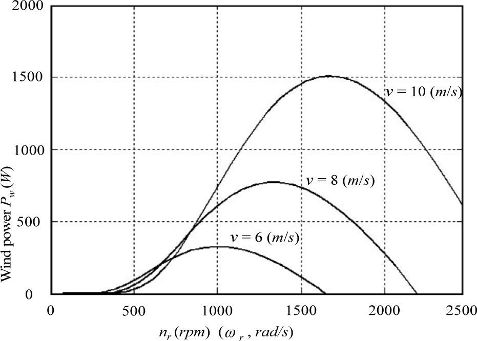
2.1Wind-turbine emulatorThe variable speed wind turbine, including the mechanical components, the PMSM direct drive PMSG and so on, is a complex electromechanical system. The steady-state wind-turbine model at various wind speeds is given by the power-speed characteristics shown in Fig. 1 for a 1.5 kw, three-blade horizontal axis wind turbine with a diameter of 2m. At a given wind speed, the operating point of the wind turbine is determined by the intersection of the turbine characteristics and the load characteristics. From Fig. 1, it is noted that the shaft power of the wind turbine is related to its wind speed v and rotor speed ωr.

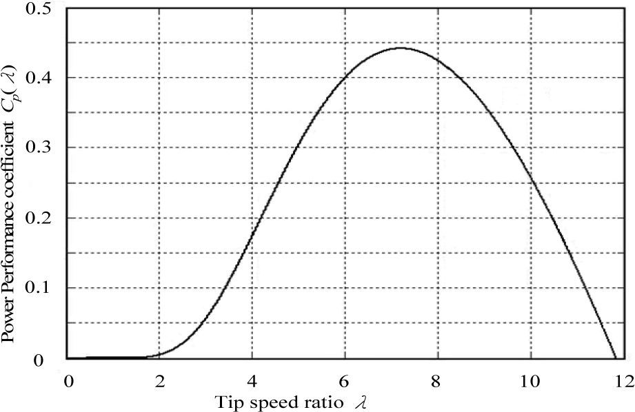
In practice, the characteristics of a wind turbine can also be represented in a simplified form of power performance coefficient Cp (λ) and tip ratio λ curve as shown in Fig. 2. The tip speed ratio of a turbine is given by [1, 4-7]
−λ characteristic of wind turbine.")

where λ is the tip ratio; Rw the turbine rotor radius in meter; ωr is the rotor speed in rad/s. The shaft power of the wind turbine is given by [1, 4-7]

where ρ is the density of air inkg/m3; A is the exposed area inm2. The Cp(λ)−λ curve is very useful in modelling the torque production of the wind turbine at different wind speeds. It is important to note that the aerodynamic efficiency is maximum at the optimum tip speed ratio. The torque value obtained by dividing the turbine power by turbine speed is formed obtained as follows:

Torque developed by the turbine Tw released to the input to the generator Te is expressed as
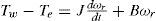
To emulate the wind turbine, the wind-turbine emulator proposed in [4-11] is adopted in this study. Moreover, the power-speed characteristic of a wind turbine is implemented by a field-oriented control PMSM servo drive. Furthermore, to emulate the wind variation in stand alone application, a closed-loop PI speed controller, which can confront the inherent nonlinear and time-varying characteristic of the PMSM servo drive, is adopted to regulate the rotor speed with the corresponding wind speed to obtain the maximum power output of the wind turbine.
2.2Field-oriented control PMSG systemThe PMSG is controlled in a synchronously rotating reference frame with the d-axis oriented along the rotor-flux vector position. In this way, a decoupled control between the electromagnetic torque and the excitation is obtained. The machine model of a PMSG can be described in the rotating reference frame as follows [1, 7-11]:


where vd and vq are d and q axis stator voltage, id and iq are d are d and q axis stator current Ld and Lq are d and q axis stator inductance, Rs is the stator resistance, ωr is rotor speed. In this study, the PMSG is controlled in a synchronously rotating reference frame with the d-axis oriented along the rotor-flux vector position. In this way, a decoupled control between the electrical torque and the excitation current is obtained. The detailed machine model of the PMSG, described in the synchronously rotating reference frame, can be found in [7-11]. By using the field-oriented control, the rotor flux in the d-axis can be controlled using d-axis stator current id=0. Moreover, the electromagnetic torque can be simplified to

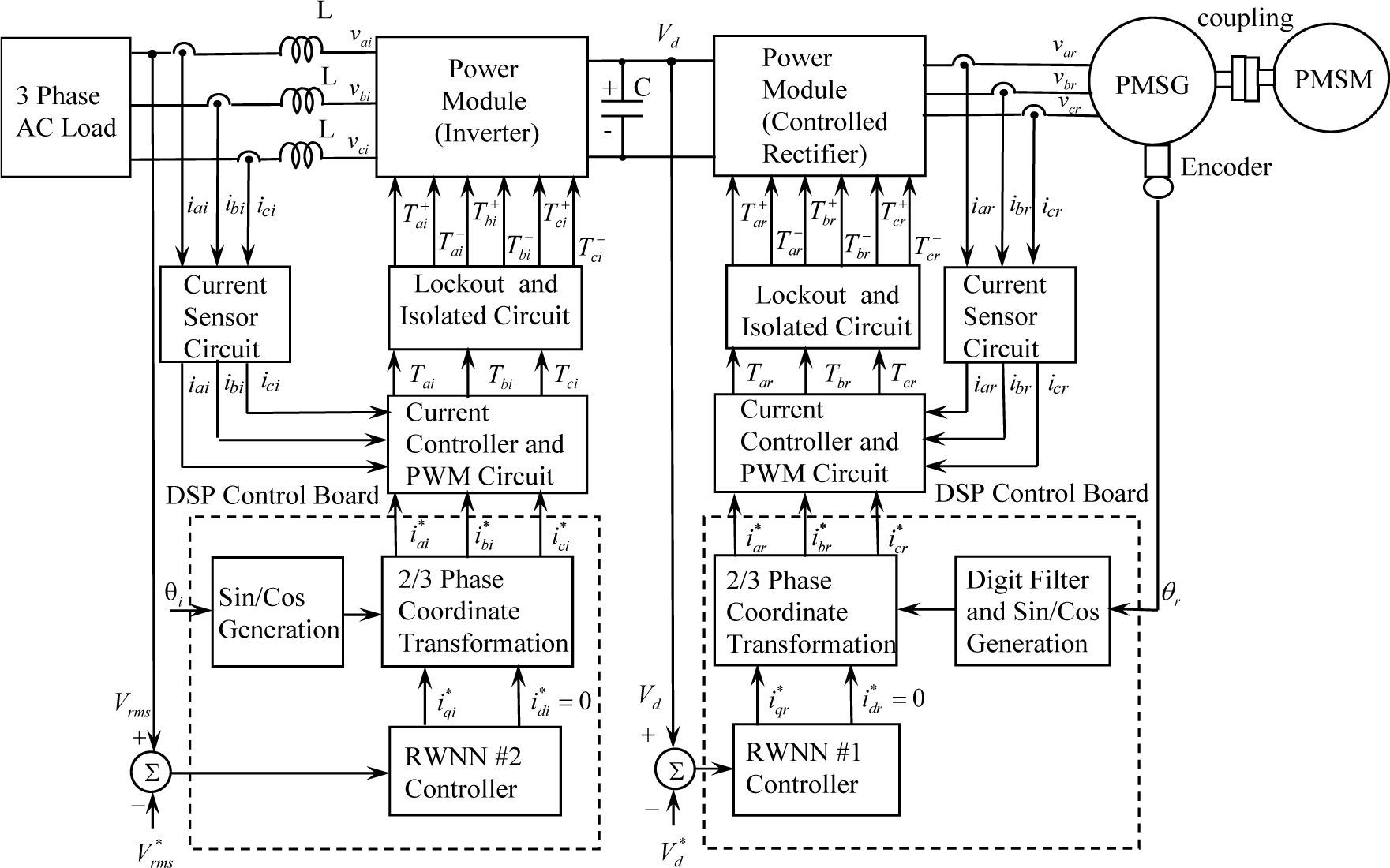
where P is the number of poles; λpm is the permanent magnet flux linkage; torque constant Kt=3Pλpm/4 The block diagram of the power circuit and control strategy of the PMSG system is shown in Fig. 3. A PMSM directly coupled to the PMSG is adopted as the primary machine to emulate the operation of the wind turbine. The wind pattern could be easily programmed using the PMSM. The variable frequency variable-voltage power generated by the PMSG is rectified to DC power by a controlled rectifier. The PMSG is controlled using field-oriented control, which consists of a ramp comparison current-controlled PWM rectifier, a field-oriented mechanism, a coordinate translation and a DC link voltage control loop using an RWNN controller.

Moreover, the DC power is converted to a constant frequency constant-voltage AC power with 60Hz 110V for the three-phase load by an inverter. The power conversion is controlled by using field-oriented control. It consists of a hysteresis comparison current-controlled PWM inverter, a field oriented mechanism, a coordinate transformation and a line voltage control loop using another RWNN controller. Furthermore, in Fig.3, θr is the rotor position of the PMSG; idr* and iqr* are the flux control current and torque control currentof the rectifier; iar*,ibr*,icr* and iar, ibr, icr are the three-phase command currents and three-phase currents of the PMSG; Tar,Tbr,Tcr are the PWM control signals of the rectifier; Vd is the DC link voltage; Vd* is the command of the DC-link voltage.
In addition, idi* and iai* are the flux control current and torque control current of the inverter; θi is the electric angular angle of the inverter; iqi*,ibi*,ici* and iai,ibi,ici, are the three-phase command currents and three-phase currents of the inverter; vai,vbi,vci are the three-phase voltages of the inverter, Tai,Tbi,Tci are the PWM control signals of the inverter; Vrms is the magnitude of the AC line voltage of the inverter; Vrms is the desired magnitude of the AC line voltage of the inverter. The PMSG used in this drive system is a three-phase Y-connected four-pole servo motor with 1.5kW 220V 10A 2000rpm type for experimental test. The parameters of the PMSG at the nominal condition are Rs=0.2Ω, Ld=Lq=6mH, Lm=6.2mH, and the adopted PMSM as the prime machine is a three-phase Y-connected four-pole servo motor with 1kW 220V 7A 2000rpm type. The block diagram of the PMSG directly-driven by PMSM connected to AC load via rectifier and inverter is shown in Fig. 3. The system is constituted by the following parts: a PMSM directly-drive PMSG, a interlocked and delay time circuits, the coordinate transformation, sinθs /cosθs and lookup table generation, hysteresis-band comparison current-controlled PWM, a controlled rectifier and a inverter, voltage control were implemented by using two independent sets TMS320C32 DSP control board and interface card.
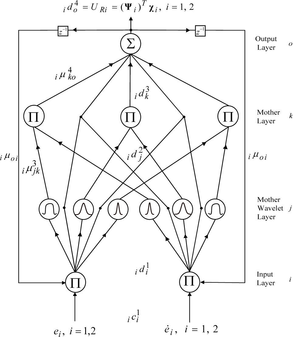
3RWNN controllerIn the two same kinds of four-layer RWNNs with input layer using feedback signals from output layer are taken into account to result in better learning efficiency. The architecture of the two same kinds of four-layer RWNNs with the input layer (the i layer), the mother wavelet layer (the j layer), the wavelet layer (the k layer) and the output layer (the o layer) is shown in Fig. 4. The activation functions and signal actions of nodes in each layer of the RWNN are described as follows:

Layer 1: Input Layer
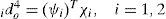
Each node i in this layer is indicated by Π, which multiplies by each other between each other for input signals. Then outputs signals are the results of product. The input and the output for each node i in this layer are expressed as

where ici1 is the input of the ith nod for ith RWNN, and idi1 is the output of the ith nod for ith RWNN. The two inputs are 1c11=e1=Vd*-Vd, 1c21=e˙1 in the PMSG system rectifier side for 1th RWNN, and 2c11=e2=Vrms*-Vrms, 2c21=e˙1 in the PMSG system inverter side for 2nd RWNN. The N denotes the number of iterations. The connecting weights i μoi are the recurrent weights between the output layer and the input layer for ith RWNN. ido4 is the output value from output layer of the RWNN for ith RWNN.
Layer 2: Mother Wavelet Layer
A family of wavelets is constructed by translations and dilations performed on the mother wavelet. In the mother wavelet layer, each node performs a wavelet φ(x) that is derived from its mother wavelet. There are many kinds of wavelets that can be used in WNN. In this paper, the first derivative of the Gaussian wavelet function φ(x)=−x exp(−x2/2) is adopted as a mother wavelet [25]. The input and the output for each node jth in this layer are expressed as

The iaij and ibij are the translations and dilations in the jth term of the ith input ici2 to the node of the mother wavelet layer for ith RWNN, and n is the total number of the mother wavelets with respect to the input nodes.
Layer 3: Wavelet Layer
Each node k in this layer is indicated by Π, which multiplies by each other between each other for input signals. Then outputs signals are the results of product. The inputs and the outputs for each node kth in this layer are expressed as

where icj3 represents the jth input to the node of layer 3 for ith RWNN; iμjk3 are the weights between the mother wavelet layer and the wavelet layer for ith RWNN. They are assumed to be unity; l1 is the total number of wavelets if each input node has the same mother wavelet nodes.
Layer 4: Output Layer
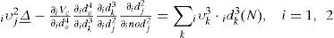
The single node oth in this layer is labeled with Σ. It computes the overall output as the summation of all input signals. The net input and the net output for node oth in this layer are expressed as

The connecting weights iμko4 are the output action strength of the oth output associated with the kth node for ith RWNN; ick4 represents the kth input to the node of layer 4 for ith RWNN. The output value of the ith RWNN can be represented as ido4.
The output values of two same kinds of four-layer RWNNs can be rewritten as UR1=(ψ1)Tχ1=iqr* and UR2=(ψ2)Tχ2=iqr*. The ψi=[ iμ114 iμ214⃛ iμl14]T,i=1,2 is the adjustable weight parameters vectors between the mother layer and the output layer of the two same kinds of four-layer RWNNs. The χi=[ ic14 ic24⃛ icl4]T,i=1,2 are the inputs vectors in the output layer of the two four-layer RWNNs, in which ick4 are determined by the selected mother wavelet function and 0≤ ick4≤1. To describe the online learning algorithm of the RWNN using supervised gradient decent method, first the energy function Vc is defined as
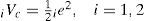
where 1e=e1=Vd*-Vd in the PMSG system rectifier side and 2e=e2=Vrms*-Vrms in the PMSG system inverter side. Then, the learning algorithm is described as follows:
Layer 4: The error term to be propagated is
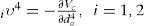
the update laws of weights can be renewed

where β is the learning rate. The connective weight iμko4 is updated according to the following equation

Layer 3: In this layer, all the connective weights are set to 1 to reduce the burden of the computation. However, the error term still needs to be propagated as

Layer 2: The error terms to be propagated are
By using the chain rule, the update laws of translations iaij and dilations ibij of Gaussian wavelet function can be renewed
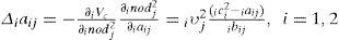
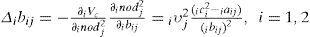
The translations iaij and dilations ibij are updated according to the following equations


By using the chain rule, the update laws of iμoi can be renewed as using the gradient descent method as

The recurrent weight iμoi is updated according to the following equations
4Experimental Results
The two same kinds of four-layer RWNNs controlled PMSG system are realized by using two same kinds of TMS320C32 DSP control system. The two current-controlled PWM power converters are implemented by using two sets IGBT switching components (BSM 100GB-120DLC) manufactured by Eupec Co. with the switching frequency of 15kHz. The two programs of the two TMS320C32 DSP control system with 2ms sampling interval are used for executing the two RWNNs and online training of the two RWNNs. Furthermore, the two RWNNs have 2, 10, 5 and 1 neuron for the input, mother wavelet, wavelet and output layers, respectively. The initialisation of the wavelet network parameters [35] is adopted to initialise the parameters of the wavelets.
To verify the control performance of the proposed two RWNNs controlled PMSG system, two cases with the flux control current idi*=0A and idr*=0A are tested to demonstrate the control performance of the PMSG system. Case 1: the rotor speed is 750rpm and step commands of Vd*=220V and Vrms*=110V are given to show the regulating response with the Δ connection three-phase load 100Ω. Case 2: the rotor speed is changed to 1500rpm and step commands of Vd*=220V and Vrms*=110V are given to show the regulating response with the Δ connection three-phase load 50Ω (Case 2); Two case is to demonstrate the capability for the stand-alone power application. The corresponding load powers are 121W and 242W under the 100Ω and 50Ω load, respectively. Some experimental results of the PI controlled PMSG system are discussed for the comparison of the control performance. Since the PMSG system is a nonlinear time varying system, the gains of the two PI controllers for both the DC link voltage regulation and AC line voltage regulation are obtained by trial and error to achieve steady-state control performance. The resulted gains are Kp=5.2, Ki=10.2 or the voltage regulation and Kp=4.8, Ki=10.8 for the AC line voltage regulation.
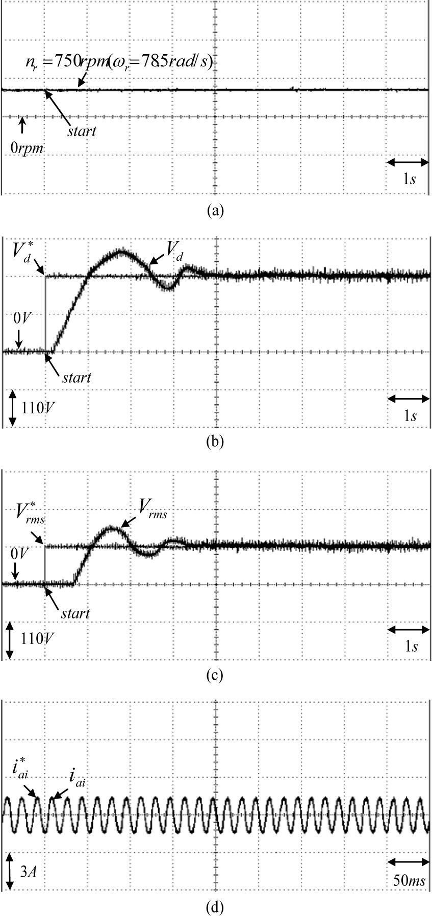
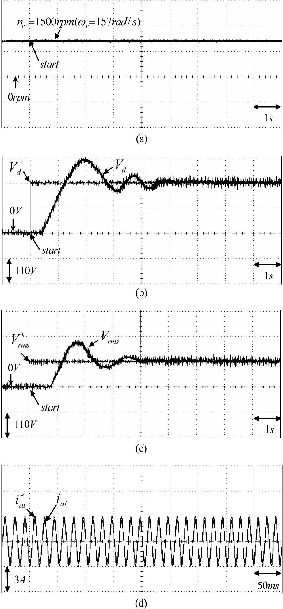
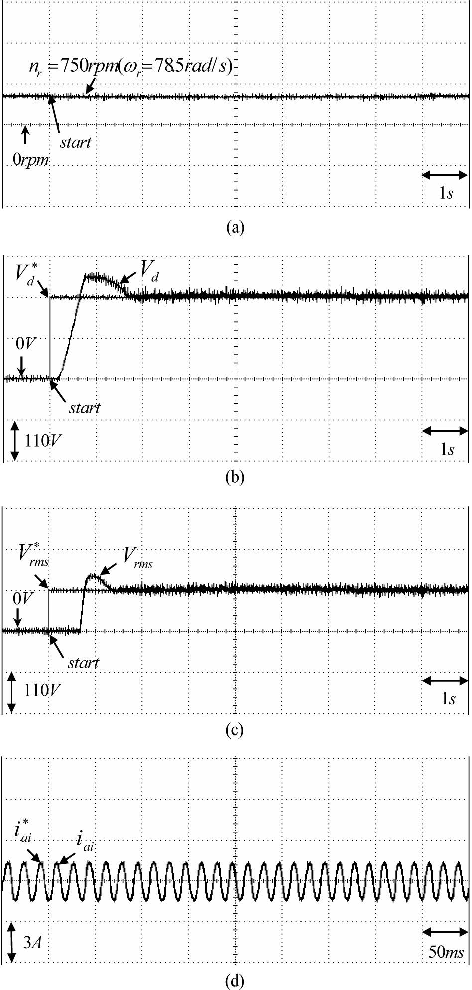
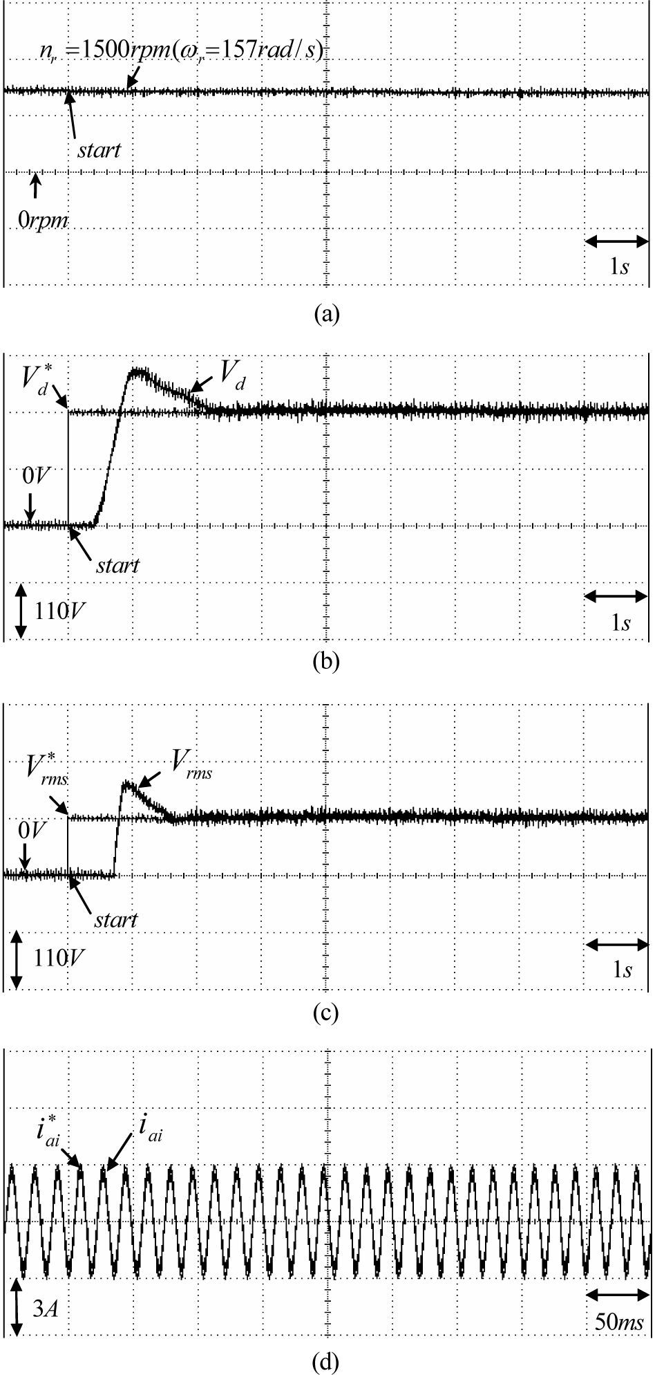
The responses of the DC link voltage Vd and the magnitude of AC line voltage Vrms. The experimental results of the PI controlled PMSG system at Case 1 and Case 2 for the Δ connection three-phase loads of 100Ω and 50Ω are shown in Figs. 5 and Fig. 6, respectively. The responses of the rotor speed nr(ωr), the DC link voltage Vd, the magnitude of AC line voltage Vrms and the command current iai* and phase current iai for Case 1 at 750rpm and for Case 2 at 1500rpm are shown in Fig. 5(a), 5(b), 5(c), 5(d) and Fig. 6(a), 6(b), 6(c), 6(d), respectively. From the experimental results, sluggish DC link voltage and AC line voltage regulating responses are obtained for the PI controlled PMSG system because of the weak robustness of the linear controller. Now, some experimental results of the proposed RWNN controlled PMSG system are tested. The experimental results of the RWNN controlled PMSG system at Case 1 and Case 2 for the Δ connection three-phase loads of 100Ω and 50Ω are shown in Figs. 7, and Fig. 8, respectively. The responses of the rotor speed nr(ωr), the DC link voltage Vd, the magnitude of AC line voltage Vrms and and the command current iai* and phase current iai for Case 1 at 750rpm and for Case 2 at 1500rpm are shown in Fig. 7(a), 7(b), 7(c), 7(d) and Fig. 8(a), 8(b), 8(c), 8(d), respectively. The overshoot and undershoot in DC link voltage and AC line voltage using the PI controller, as shown in Figs. 5(b), 5(c) and 6(b), 6(c) are also much improved by the proposed RWNN controller as shown in Figs. 7(b), 7(c) and 8(b), 8(c).
 rotor speed nr(ωr) (750rpm, 100Ω), (b) regulating response of DC link voltage (750rpm, 100Ω), (c) regulating response of AC line voltage (750rpm, 100Ω), (d) command current iai* and phase current.iai (750rpm, 100Ω).")
Experimental results of PMSG system using PI controller for Case 1: (a) rotor speed nr(ωr) (750rpm, 100Ω), (b) regulating response of DC link voltage (750rpm, 100Ω), (c) regulating response of AC line voltage (750rpm, 100Ω), (d) command current iai* and phase current.iai (750rpm, 100Ω).
 rotor speed nr(ωr) (1500rpm, 50Ω), (b) regulating response of DC-link voltage(1500rpm, 50Ω),(c) regulating response of AC line voltage (1500rpm, 50Ω), (d) command current iai* and phase current iai (1500rpm, 50Ω).")
Experimental results of PMSG system using PI controller for Case 2: (a) rotor speed nr(ωr) (1500rpm, 50Ω), (b) regulating response of DC-link voltage(1500rpm, 50Ω),(c) regulating response of AC line voltage (1500rpm, 50Ω), (d) command current iai* and phase current iai (1500rpm, 50Ω).
 rotor speed nr(ωr) (750rpm, 100Ω), (b) regulating response of DC link voltage (750rpm, 100Ω), (c) regulating response of AC line voltage (750rpm, 100Ω), (d) command current iai* and phase current iai (750rpm, 100Ω).")
Experimental results of PMSG system using RWNN controller for Case 1: (a) rotor speed nr(ωr) (750rpm, 100Ω), (b) regulating response of DC link voltage (750rpm, 100Ω), (c) regulating response of AC line voltage (750rpm, 100Ω), (d) command current iai* and phase current iai (750rpm, 100Ω).
 rotor speed nr(ωr) (1500rpm, 50Ω), (b) regulating response of DC link voltage (1500rpm, 50Ω), (c) regulating response of AC line voltage (1500rpm, 50Ω), (d) command current iai* and phase current iai (1500rpm, 50Ω).")
Experimental results of PMSG system using RWNN controller for Case 2: (a) rotor speed nr(ωr) (1500rpm, 50Ω), (b) regulating response of DC link voltage (1500rpm, 50Ω), (c) regulating response of AC line voltage (1500rpm, 50Ω), (d) command current iai* and phase current iai (1500rpm, 50Ω).
This study demonstrated the implementation of the two RWNN controllers to regulate both the DC link voltage of the rectifier provided by PMSG system and AC line voltage of the inverter in order to supply for stand alone. First, the field-oriented mechanism was implemented for the control of the PMSG system. Then, the proposed two RWNNs controllers were proposed to regulate the DC-link voltage of the rectifier and the AC line voltage of the inverter. Moreover, the effectiveness of the proposed control scheme has been confirmed by some experimental results. Furthermore, the control performance of the proposed RWNN control PMSG system is robust with regard to different operating conditions of the PMSG.
The two major contributions of this study are: (1) the successful development of the PMSG system for stand-alone power applications through a rectifier and an inverter; (2) the successful application of the RWNN controller on the PMSG system to regulate the DC link voltage of the rectifier and the AC line voltage of the inverter with robust control performance. Because of the weak robustness of the linear controller for the PI control PMSG system, sluggish DC-link voltage and AC line voltage regulating responses are obviously obtained from the experimental results. Finally, the better control performance of the proposed control system is verified in comparison with the PI controller by the experimental results.
AcknowledgementsThe author would like to acknowledge the financial support of the National Science Council in Taiwan, R.O.C. through its grant NSC 99-2221-E-239-040-MY3.