The maximum power point tracking is a very important scheme of many renewable energy. It can increase the power efficiency. However, many traditional methods has defects for the applications. This study proposed a novel fractional order incremental conductance algorithm (FOINC) for the maximum power point tracking design of small wind power systems. The proposed method is prompt in the transient of maximum power point tracking and has good steady-state response. Moreover, it can increase the maximum power tracking efficiency of system without changing the wind power system equipments. The comparison between the traditional incremental conductance method (INC) and Perturbation and Observation (P&O) proved the reliability and effectiveness of the proposed method.
The renewable energy source is being developed actively in various countries in recent years, among all the available renewable energy sources, the solar energy and wind power have attracted most attention. The wind power is very attractive, because it converts wind energy into kinetic energy, the vanes guide the generator to rotate, it is one of the cleanest energy sources. At present, the PMSG is one of the most frequently used wind turbines for compactness, high power density, low maintenance cost and easy control (Barakati, Kazerani, & Chen, 2005; Jazaeri, Samadi, Najafi, & Noroozi-Varcheshme, 2012; Dumnic, Katic, Vasic, Milicevic, & Delimar, 2012). The real environment has different wind speed conditions, the wind turbine will have different power characteristic curves, so the Maximum Power Point Tracking (MPPT) is required, so that the output of wind power system is kept at maximum power in different wind speed conditions.
Many MPPT technologies have been implemented in wind power systems in previous literatures, such as Incremental Conductance method (INC) (Kish, Lee, & Lehn, 2012; Faraji, Rouholamini, Naji, Fadaeinedjad, & Chavoshian, 2014; Sera, Mathe, Kerekes, Spataru, & Teodorescu, 2013), P&O (Sera et al., 2013; Mahdi, Tang, & Wu, 2012; Femia, Petrone, Spagnuolo, & Vitelli, 2004), and Hill-Climbing Search Algorithm (HCS) (Raza Kazmi, Goto, Hai-Jiao, & Ichinokura, 2011; Yamakura & Kesamaru, 2012). However, most of wind power system control depends on wind speed sensing element, and this type of system needs additional wind speed sensor, so that it is confined to the cost and complexity of sensor (Koutroulis & Kalaitzakis, 2006). The FOINC proposed in this paper only captures the voltage and current of PGMG after the full-bridge rectifier converts the AC generated by the generator into DC. The DC/DC converter as booster adjusts the duty ratio, and the switching pulse width duty cycle of booster is adjusted by algorithm, so as to maximize the output power.
As compared with INC and P&O, the FOINC maximum power tracking controller proposed in this paper is prompt in the transient of MPPT and has good steady-state response. In the real environment, the module life loss resulted from power waveform oscillation can be reduced, the output efficiency of wind turbine is increased and the lost cost is reduced. In other words, the proposed method is practicable for small wind power systems.
2Brief introduction to wind power systemsIn terms of the acquisition of wind energy, the air flow generates air pressure to rotate the vanes to capture the kinetic energy of wind. Then it is converted into useful kinetic energy or mechanical energy. The energy is contained in the wind, and the rotor blades rotate in wind. Under the effect of aerodynamic force, the vanes generate torque. The power Pωn generated by wind turbine is expressed as equation (1) (Hau, 2005):
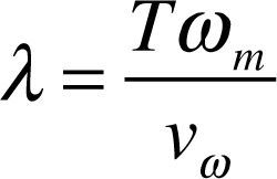
where ρ is the air density, R is the blade radius, Vω is the wind speed, Cp is the coefficient of performance of wind turbine. Cp includes the blade tip speed ratio λ. λ is defined as the relationship between blade tip speed and wind speed, expressed as equation (2):
where ωm is the blade rotation speed. Figure 1 shows the power characteristic curves in different wind speed conditions (Nakamura, Morimoto, Sanada, & Takeda, 2002).
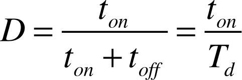
2.1Wind power system architectureThe wind power system architecture proposed in this paper is shown in Figure 2, the wind turbine is coupled to the PMSG directly, connected to a set of rectifier, converting the AC of generator into DC. The DC voltage and current signals are obtained, and the signals are connected to the DC-DC boost converter. The MPPT is used to control signals and adjust the duty cycle of switching pulse width modulation (PWM). Finally, the DC-DC boost converter is connected to the load, and the system output power is measured. The basic structure of the converter is shown in Figure 3. When the switch is “on”, the wind power system charges the inductor via the switch. When the switch is “off”, the wind power system releases the inductance energy to the load via diode. The output voltage and current can be changed by different input voltages and currents by adjusting the duty ratio. When the switch is off toff and on ton, the current through inductor can be expressed as:
Duty ratio (D) of control switch is:
As the one-cycle voltage variation of inductor is 0, i.e. ▵IL+ = ▵IL–.
The equation of output voltage Vo can be obtained:
3Design of algorithm and control methodThis study used MATLAB R2010a Simulink to build the simulated small wind power system architecture and to design the control method. Figure 4 shows the simulation diagram of the wind power system. The module FOINC can be replaced by different MPPTs for duty cycle control of different switching pulse adjustment control methods.
3.1Hill-Climbing Search (HCS)The most frequently used algorithm in wind power systems at variable wind speed is the HCS. This algorithm looks for the optimum speed of wind turbines according to the perturbation of wind speed to complete MPPT. The improved HCS can be derived from this algorithm. The detailed algorithm flowchart and content can be seen in literature (Dalala, Zahid, W, Younghoon, & Jih-Sheng, 2013).
3.2Perturbation and Observation (P&O)The P&O is one of the most extensively used methods in recent years. Its advantages include simple architecture, fewer required parameters and being free from atmospheric influence. The terminal voltage and output power of wind turbine are changed by changing the duty cycle D, and whether the changed output power increases continuously or not is observed. The power point on the left or right of curve is judged according to the input voltage. Finally, whether the duty cycle D keeps changing in the same direction or not is determined. The maximum power point can be reached by such repeated perturbation, observation and comparison. However, this method uses periodic perturbation, so there is oscillation at maximum power point, resulting in unnecessary power loss of system.
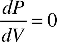
3.3Incremental Conductance method (INC)The INC is based on power-voltage (P – V) curve of solar cell, equations (7) or (8) must be met at maximum power point:
where Io and Vo are the current and voltage captured at previous point in time, ΔI and ΔV are the variation of current and voltage in unit time. However, when the method processes MPPT, the offset ΔV determines the speed of reaching the MPP and the perturbation after the MPP is reached. The decision must be made by the user.
3.4Fractional order incremental conductance methodThe fractional-order differentiator is often applied to signal processing, adaptive control, active control, linear and nonlinear feedback control. At present, many computing applications of fractional-order derivative have been proposed, according to the definition of Riemann-Liouville and Grunwald-Letnikov (Igor, 1999; Ma & Hori, 2007; Kenneth & Bertram, 1993). General fractional-order differentiator can be expressed as:
where γ() represents the γ function (gamma function), α is the order number of derivative, when its value is 0 < α < 1, representing the physical phenomenon of fractional order, its application can refer to Tavakoli-Kakhki, Haeri, & Tavazoei (2013), Ma and Hori (2007), and Saha et al. (2010).
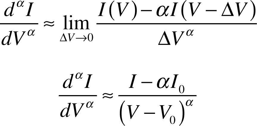
General fractional-order differentiator can be expressed as equation (9), when the INC is used, equation (8) can be expressed as:
If α > 0 in ΔVα, the geometric interpretation of fractional order can be represented as Figure 5. The slope is a straight line when α = 1, i.e. general first derivative. Therefore, 0 < α < 1 presents the form of fractional-order derivative, approximate to curve form, referring to literature (Shantanu, 2008). The result of using equation (9) in the right half of equation (8) is:
where res(γ,−z)=z!(−1)z,z=0,−1,−2,−3,...,, and γ(0) = res (γ, 0), res represents the residue under complex plane.
The voltage V, current I and power P are used as calculated captured signals in this paper. The variance in voltage and current ΔV = V – Vo, and ΔI = I – Io, the slope is the slope of power-voltage curve of wind turbine, and the variation of partial voltage and current of fractional-order differentiator approximates as dαI= I – αIo, dVα = (V – Vo)α.
The control flow of FOINC proposed in this paper is shown in Figure 6.
4Simulation analysis results and comparisonThis study used MATLAB R2010a Simulink to build the model and controller of small wind power systems, and proposed the PMSG-based wind power system. The simulation compared the INC and P&O with FOINC proposed in this paper at constant wind speed and variable wind speed.
The first simulated condition is constant wind speed of 12.5 m/s, as shown in Figure 7. The INC and P&O and FOINC proposed in this paper are analyzed and compared in this wind speed condition.
As shown in Figure 8, in the constant wind speed, the MPPT speed of FOINC proposed in this paper is better than P&O and INC, and the steady-state response is smoother than P&O and INC, thus reducing unnecessary power loss, and increasing the efficiency, proving the practicability of the proposed method.
The second simulated condition is variable wind speed for test and comparison of algorithms. The wind speed conditions are 12.5 m/s and 10 m/s, as shown in Figure 9. The INC and P&O and FOINC proposed in this paper are analyzed and compared in the wind speed condition.
As shown in Figure 10, the MPPT speed of FOINC proposed in this paper is better than P&O and INC, and the amplitude in steady-state is steadier than P&O and INC. Therefore, a better response curve can be obtained in the variable wind speed condition, proving the feasibility of the proposed method.
5ConclusionsThe FOINC proposed in this paper can control the algorithm only by capturing the voltage and current generated by the wind power system without adjusting the parameter setting for different systems. The transient tracking is prompt and the perturbation after steady-state is better than existing methods. According to the simulation results, due to fewer required parameters, high speed and good stability, the small wind power system is free from excess sensing elements, so that the cost is reduced. The FOINC proposed in this paper can be applied and implemented to the MPPT of small wind power systems in the future.


