This paper presents a comparison between some well-known control schemes such as feedback, feedback plus feed-forward, cascade and cascade plus feed-forward for controlling a third-order process. The controller applied in various control schemes is a PID controller that has been tuned using Ziegler Nichols (ZN) and relay auto-tuning (RA) methods. The comparative analysis is based upon various performance measures such as rise time (tr), settling time (ts), maximum overshoot (Mp), steady-state error (ess), integral of absolute error (IAE), integral of square error (ISE), integral of time square error (ITSE), and integral of time absolute error (ITAE). Simulation results show that the RA method provides superior performance in case of feedback plus feed-forward and cascade control schemes. On the other hand, the ZN method proves to be better in case of cascade plus feed-forward control scheme.
In Process industry generally, the processes are complex, having time delays, and may have different type of nonlinearities. Therefore, it is not always possible to control them with a classical control scheme such as a feedback control scheme. Therefore to control such type of systems advance control schemes such as feedback plus feed-forward, cascade and cascade plus feed-forward may be required.
The most frequently implemented controller in different control schemes is the PID controller, due to its simple configuration and easy implementation (Astrom & Hagglund, 1995). A PID controller, also known as a three-term controller, has three principal control actions, i.e. the proportional action, the integral action and the derivative action. All of these control actions are summed up together to obtain a single control effort. The proportional action provides a change in the manipulated variable relative to the error signal and is used to remove a large amount of error; the integral action provides a signal proportional to the time integral of error, and its main function is to reduce the steady-state error or offset, while the derivative action provides a signal proportional to the derivative of error, and its function is to reduce maximum overshoot. Mathematically, the output from a PID controller is given as:
where u(t) is the control signal, e(t) the error signal defined as the difference between the set-point and the output.
Kc = proportional gain.
τI = integral time.
τD = derivative time.
Various tuning methods have been discussed within the literature for finding out the parameters of a PID controller (Tan et al., 2006; Chopra et al., 2014). The stereotypical tuning methods include Ziegler Nichols (ZN), relay auto-tuning (RA), pole placement and internal model control (IMC). While the intelligent methods make use of fuzzy logic, genetic algorithms (GA), artificial neutral networks and particle swarm optimization (PSO) for finding the PID parameters.
Brown et al. (1993) proposed a PID self-tuning controller based on pole placement method for controlling an aluminum rolling mill. Zhuang and Atherton (1993) proposed tuning of PID controller with time integral performance criteria. ZN method was used to determining the controller parameters. Sousa et al. (1997) proposed internal model controller (IMC) with a fuzzy model for air-conditioning system. Different control schemes have been discussed within the literature by various researchers. Peng et al. (2013) proposed an internal model based robust inversion feed-forward and feedback control approach for LPV system while Zhang et al. (2014) presented a discrete feed-forward and feedback optimal tracking control scheme for a steel jacket plat subjected to external wave force. Zhong and Luo (2011) presented a comparative analysis between a single-loop control system and a cascade control system for a third-order process. Zhong et al. (2012) proposed model matching methods and approximate dynamic inversion techniques for designing feed-forward controllers. A feed-forward velocity control scheme for a DC motor based on the inverse dynamic model has been presented in the literature by Barakat and Rajagopalan (1996). A robust cascade control system has been implemented for controlling central air-conditioning system by Wang et al. (2008). Mohammadzaheri et al. (2009) proposed a feed-forward control law based upon the concept of control equilibrium point.
This paper presents a comparison among different control schemes such as feedback, feedback plus feed-forward, cascade and cascade plus feed-forward using PID controllers.
The paper is organized as follows: section 2 gives a brief introduction to different control schemes; in section 3 tuning of PID controller, using ZN and RA methods has been discussed; the simulation results are given in section 4, and finally the paper is concluded.
2Control Schemes2.1Feedback ControlA feedback control system maintains a prescriptive relationship between the process output and set point by comparing them and using the error signal as a means of control. It is the simplest form of closed loop control scheme (Bandi & Mehta, 2012). Feedback control system has many daily routine applications; for instance, consider an automobile speed control or an air conditioner temperature control system which uses the difference between the actual and the desired speed or temperature to change the manipulated variable. Since the system output is used to regulate its input, such a device is said to be a closed-loop control system. The block diagram of a feedback control system is shown in Figure 1.
From Figure 1, it can be observed that the error signal which is the difference between the set-point and the output variable acts on the input for the controller which can be a PID controller. The controller generates the manipulated variable to obtain the desired plant output.
2.2Feed-forward ControlThe objective of feed-forward control is to measure disturbances and remunerate for them before the controlled variable varies from the set point. The basic approach is to measure a disturbance directly and take control action to erase its impact upon the process output (Bequette, 2003). The performance of the feed-forward scheme depends on the accuracy of the process and the disturbance models. Feed-forward control has the possibility for impeccable control. However, because of modeling errors and unmeasured disturbances, a flawless feed-forward control cannot be achieved. Feed-forward control cannot be used alone and is used in combination with feedback control. The role of a feedback controller is to take care of the modeling errors and unmeasured disturbances which insure offset-free control. Feed-forward control acts immediately on occurrence of disturbance, without waiting for a change to the process variable (Bequette, 2003). The block diagram of a feed-forward control scheme is shown in Figure 2.
Feed-forward control (Bequette, 2003).
From the block diagram, it can be revealed that the feed-forward controller takes immediate action in response to a disturbance acting upon the system.
2.3Feed-forward Plus FeedbackA combination of feed-forward plus feedback control strategy has been shown in Figure 3. Here the feed-forward controller will reduce or eliminate the effect of outer disturbances acting upon the system while the feedback control loop is a simple closed-loop control loop which will respond with a change in the set point (Bequette, 2003).
Feedback plus feed-forward control (Bequette, 2003).
Feed-forward plus feedback control is one of the commonly used advanced control techniques. Combining feed-forward with the feedback control scheme can significantly give better performance over simple feedback control under the effect of a disturbance that can be measured before it affects the process output. Feed-forward compensates for load upsets before they are detected by the feedback control system as an error. If the feedback controller is used alone, they only react for a load upset after an error is detected between the process variable and the set point.
2.4Cascade ControlCascade control is most commonly used within steam process industries. The cascade scheme consists of two loops, an inner loop and an outer loop. The cascade control scheme is beneficial only when the inner loop has faster dynamics as compared to the outer loop (Song et al., 2003).
The cascade control scheme has been shown in Figure 4.
Cascade control system (Bequette, 2003).
As shown in the block diagram, the inner loop is controlling the secondary process that can be flow through a valve, while the outer loop is used to control the primary process. The two loops are tuned in a systematic manner. Initially the inner loop controller is tuned first while keeping the outer loop controller in manual mode. The tuning of inner loop controller can be done using direct synthesis, ZN or RA methods. Thereafter the outer loop controller is tuned to complete the tuning process.
2.5Cascade Plus Feed-forwardA combination of cascade and feed-forward control has been shown in Figure 5.
Cascade plus feed-forward control (Bequette, 2003).
From Figure 5, we see that the primary and the secondary processes are controlled by a cascade control strategy, while the disturbance rejection has been obtained using a feed-forward control strategy.
3Tuning MethodsTuning a controller is a method of determining the parameters of a PID controller for a given system. Some of these tuning methods are discussed below.
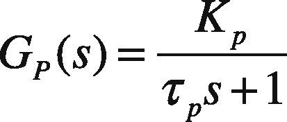
3.1Direct Synthesis MethodThis tuning technique is model based. The specified technique uses an identified process model in conjunction with a user specified closed-loop response characteristic. A positive aspect to this approach is that it provides insight on the role of the “model” in control system design. A limitation to the approach is that a PID controller may not be realized unless an appropriate model form is used to synthesize the control law.The direct synthesis method is explained as follows (Rice & Cooper, 2004); consider a first order system given as:
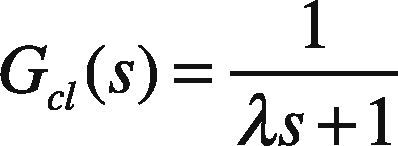
Since in direct synthesis method a desired closed loop response is being selected. Therefore considering:
For a feedback system
or
Putting Eq. (2) and Eq. (3) in Eq. (5)
or
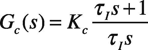
For a standard PI controller
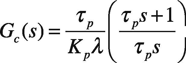
By comparing Eq. (7) and Eq. (8) we get:
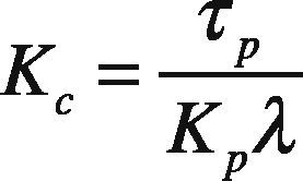
Here λis a tuning parameter. Smaller the value of λ, faster will be the closed loop response and vice versa.
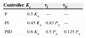
3.2Ziegler-Nichols Tuning MethodThe most popular tuning methodology was proposed by Ziegler and Nichols in 1942 (Ogata, 2009). The closed-loop tuning method requires the determination of the ultimate gain and ultimate period. This can be achieved by adjusting the controller gain until the system undergoes sustained oscillations at the ultimate gain or critical gain (Ku), whilst maintaining the integral time constant at infinity and the derivative time constant at zero. The time period of oscillations is represented as Pu. By using Table 1, the PID controller parameters can be determined.
Tuning parameters for Ziegler and Nichols closed loop ultimate gain method (Ogata, 2009).
| Controller | Kc | τI | τD |
|---|---|---|---|
| P | 0.5Ku | — | — |
| PI | 0.45Ku | 0.83 Pu | — |
| PID | 0.6Ku | 0.5 Pu | 0.125 Pu |
Relay-based auto-tuning is a simple method to tune PID controllers that avoids trial and error, and minimizes the possibility of operating the plant close to the stability limit (Ogata, 2009). Block diagram of simple feedback auto-tuning system is shown in Figure 6.
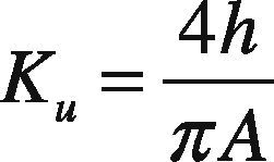
Auto-tuning is based on the idea of using an on/off controller (called a relay controller). Initially, the plant oscillates without a definite pattern around the nominal output value until a definite and repeated output response can be identified. When the desired response pattern has been reached, the oscillation period (Pu) and the amplitude (A) of the plant response can be measured and used for PID controller tuning. In fact, the ultimate gain can be computed as:
where h=amplitude of the PID controller output, and A=amplitude of the plant response.
4Simulation ResultsThe primary process is a third order process and is given as:
The secondary process is a first order process.
In this paper, the plant GP2(s) has been tuned by direct synthesis method and the plant GP1(s) has been tuned by ZN and RA tuning methods. The unit step responses for feed-forward plus feedback, cascade, and cascade plus feed-forward control systems using ZN and RA methods are shown in Figures 7–9.
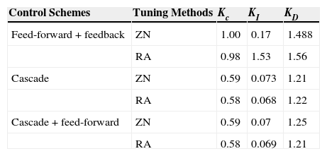
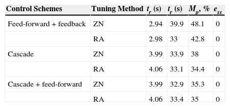
Table 2 and Table 3 show gains of PID control and quantitative analysis of various control schemes using different tuning methods respectively.
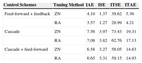
Table 4 shows the time integral performance indices comparison of various control schemes using different tuning methods.
Time integral performance indices comparison with different control schemes.
| Control Schemes | Tuning Method | IAE | ISE | ITSE | ITAE |
|---|---|---|---|---|---|
| Feed-forward + feedback | ZN | 4.10 | 1.37 | 39.62 | 5.36 |
| RA | 3.57 | 1.27 | 28.99 | 4.21 | |
| Cascade | ZN | 7.56 | 3.97 | 73.43 | 19.31 |
| RA | 7.08 | 3.82 | 62.76 | 17.13 | |
| Cascade + feed-forward | ZN | 6.58 | 3.27 | 58.05 | 14.63 |
| RA | 6.65 | 3.31 | 59.15 | 14.93 |
In this paper, a comparison between the different control schemes (i.e. feedback, feedback plus feed-forward, cascade and cascade plus feed-forward) has been carried out for controlling a third-order process. The comparative analysis has been obtained in terms of various performance specifications such as tr, tp, ts, Mp and ess. Furthermore, a comparative analysis has also been made in terms of time integral performance specifications like IAE, ISE, ITSE and ITAE. The PID controllers used in the above control schemes have been tuned using ZN, RA and direct synthesis methods. Simulation results show that in case of feed-forward plus feedback and cascade control schemes the RA method provides better performance in terms of ts, Mp and various time performance specifications than the ZN tuning method.


