Assuming that the thermo-creep response of the material is governed by Norton’s law, an analytical solution is presented for the calculation of time-dependent creep stresses and displacements of homogeneous thick-walled cylindrical pressure vessels. For the stress analysis in a homogeneous pressure vessel, having material creep behavior, the solutions of the stresses at a time equal to zero (i.e. the initial stress state) are needed. This corresponds to the solution of materials with linear elastic behavior. Therefore, using equations of equilibrium, stress-strain and strain-displacement, a differential equation for displacement is obtained and then the stresses at a time equal to zero are calculated. Using Norton’s law in the multi-axial form in conjunction with the above-mentioned equations in the rate form, the radial displacement rate is obtained and then the radial, circumferential and axial creep stress rates are calculated. When the stress rates are known, the stresses at any time are calculated iteratively. The analytical solution is obtained for the conditions of plane strain and plane stress. The thermal loading is as follows: inner surface is exposed to a uniform heat flux, and the outer surface is exposed to an airstream. The heat conduction equation for the one-dimensional problem in polar coordinates is used to obtain temperature distribution in the cylinder. The pressure, inner radius and outer radius are considered constant. Material properties are considered as constant. Following this, profiles are plotted for the radial displacements, radial stress, circumferential stress and axial stress as a function of radial direction and time.
Axisymmetric component such as a cylindrical vessel is more often used as the basic process component in various structural and engineering applications such as pressure vessels (e.g. hydraulic cylinders, gun barrels, pipes, boilers, fuel tanks and gas turbines), accumulator shells, cylinders for aerospace industries, nuclear reactors and military applications, pressure vessel for industrial gases or a media transportation of high-pressurized fluids and piping of nuclear reactors [1, 2]. In most of these applications, the cylinder has to operate under severe mechanical and thermal loads, causing significant creep and thus reducing its service life [1, 2, 3, 4]. Therefore, the analysis of long term steady state creep deformations is very important in these applications. [1, 2].
Weir [5] investigated creep stresses in pressurized thick walled tubes. Bhatnagar and Gupta [6] obtained solution for an orthotropic thick-walled internally pressurized cylinder by using constitutive equations of anisotropy creep and Norton’s creep law. Yang [7] obtained an analytical solution to calculate thermal stresses of thick cylindrical shells made od functionally graded materials with elastic and creep behavior. Creep damage simulation of thick-walled tubes using the theta projection concept investigated by Loghman and Wahab [8]. Gupta and Pathak [9] studied thermo creep analysis in a pressurized thick hollow cylinder. Assuming that the creep response of the material is governed by Norton’s law, Zamani Nejad et. al. [10] presented a new exact closed form solution for creep stresses in isotropic and homogeneous thick spherical pressure vessels. In this paper all results have been obtained in nondimensional form. Hoseini et. al. [11] presented a new analytical solution for the steady state creep in rotating thick cylindrical shells subjected to internal and external pressure. In this paper the creep response of the material is governed by Norton’s law and exact solutions for stresses are obtained under plane strain assumption. Wah [12] developed a theory for the collapse of cylindrical shells under steady-state creep and under external radial pressure and high temperature (300 to 500 F). Pai [13] studied the steady-state creep of a thick-walled orthotropic cylinder subjected to internal pressure. They observed that the creep anisotropy has a significant effect on the cylinder behavior particularly in terms of creep rates which may differ by an order of magnitude compared to an isotropic analysis. Sankaranarayanan [14] studied the steady creep behaviour of thin circular cylindrical shells subjected to combined lateral and axial pressures. The analysis is based on the Tresca criterion and the associated flow rule. Assuming that the total strain is consist of elastic and creep components, Murakami and Iwatsuki [15] investigated the transient creep analysis of circular cylindrical shells on the basis of the strain-hardening and time-hardening theories. Murakami and Suzuki [16] developed a numerical analysis of the steady state creep of a pressurized circular cylindrical shell on the basis of Mises’ criterion and the power law of creep. Sim and Penny [17] studied the deformation behaviour of thick-walled tubes subjected to a variety of loadings during stress redistribution caused by creep. Murakami and Iwatsuki [18] investigated the steady state creep of simply supported circular cylindrical shells with open ends under internal pressure by using Nortons’s law. Using finite-strain theory Bhatnagar and Arya [19] studied the creep bchaviour of a thick-walled cylinder under large strains. Murakami and Tanaka [20] investigated the creep buckling of clamped circular cylindrical shells subjected to axial compression combined with internal pressure with special emphasis on the concept of creep stability and the accuracy of the analysis. Jahed and Bidabadi [21] presented a general axisymmetric method for an inhomogeneous body for a disk with varying thickness. An approximation has been employed during their solution algorithm. It means that they avoid considering the differentiation constitutive terms of governing equations for creep analysis. Chen et al. [22] studied the creep behavior of a functionally graded cylinder under both internal and external pressures. They observed that an asymptotic solution can be derived on the basis of a Taylor series expansion if the properties of the graded material are axisymmetric and dependent on radial coordinate. In order to investigate creep performance of thick-walled cylindrical vessels or cylinders made of functionally graded materials, You et al. [23] proposed a simple and accurate method to determine stresses and creep strain rates in thick-walled cylindrical vessels subjected to internal pressure. Based on the power law constitutive equation, Altenbach et al. [24] presented the classical solution of the steady-state creep problem for a pressurized thick-walled cylinder. In this paper they applied an extended constitutive equation which includes both the linear and the power law stress dependencies. Singh and Gupta [25-28] developed a mathematical model to describe the steady-creep behaviour of functionally graded composite cylinders containing linearly varying silicon carbide particles in a matrix of pure aluminum involving threshold stress-based creep law. The model developed is used to investigate the effect of gradient in distribution of SiCp on the steady-state creep response of the composite cylinder. Assuming total strains to be the sum of elastic, thermal and creep strains, Loghman et al. [29] studied the time-dependent creep stress redistribution analysis of a thick-walled FGM cylinder placed in uniform magnetic and temperature fields and subjected to an internal pressure. Following Norton’s law for material creep behavior and using equations of equilibrium, strain displacement and stress-strain relations in the rate form and considering Prandtl-Reuss relations for creep strain rate-stress equation, they obtained a differential equation for the displacement rate and then calculated the radial and circumferential creep stress rates. Sharma et al. [30] investigated the creep stresses in thick-walled circular cylinders under internal and external pressure, using transition theory, which is based on the concept of ‘generalized principal strain measure’. Jamian et al. [31] investigated the creep analysis for a thick-walled cylinder made of functionally graded materials (FGMs) subjected to thermal and internal pressure. Singh and Gupta [32] studied the steady state creep behavior in a functionally graded thick composite cylinder subjected to internal pressure in the presence of residual stress. Hoffman’s yield criterion is used, to describe the yielding of the cylinder material in order to account for residual stress. In this article, assuming that the thermo-creep response of the material is governed by Norton’s law, an analytical solution is presented for the calculation of time- dependent creep stresses and displacements of thick-walled cylindrical pressure vessels under internal heat flux.
2Heat conduction formulationIn the steady state case, the heat conduction equation for the one-dimensional problem in polar coordinates simplifies
where T = T(r) is temperature distribution in the thick cylindrical pressure vessel. We may determine the temperature distribution in the cylindrical vessel by solving Eq. 1 and applying appropriate boundary conditions. Eq. 1 may be integrated twice to obtain the general solution
The boundary conditions for when that inner surface is exposed to a uniform heat flux qa, and the outer surface is exposed to an airstream temperature, are as follows
Here λ, T∞ and h∞ are thermal conductivity, temperatures and heat transfer coefficient of the surrounding media, respectively. Substituting Eq. 2 into Eq. 3 yields
Therefore:
3Linear elastic behavior analysis of the cylinderFor the stress analysis in a cylinder, having material creep behavior, the solutions of the stresses at a time equal to zero (i.e. the initial stress state) are needed, which correspond to the solution of materials with linear elastic behavior. In this section, equations to calculate such linear stresses in cylinder analytically will be given briefly for two cases: (a) plane strain; (b) plane stress. Consider a thick-walled cylinder with an inner radius a, and an outer radius b, subjected to internal pressure Pi and external pressure Po that are axisymmetric (Figure 1).
3.1The case of plane strainThe displacement in the r-direction is denoted by ur. Three strain components can be expressed as
where εrr, εθθ and εzz are radial, circumferential and axial strains. The stress-strain relations for homogenous and isotropic materials are
where σrr, σθθ and σzz are radial, circumferential and axial stresses, respectively. Here E, v and α are the Young’s modulus, Poisson’s ratio and thermal expansion coefficient, respectively.
The equilibrium equation of the cylindrical pressure vessel, in the absence of body forces, is expressed as
Using Eqs. 5-12, the essential differential equation for the displacement ur can be obtained as
For a homogenous and isotropic material, Young’s modulus, Poisson’s ratio v, and the thermal expansion coefficient α, are constant, therefore, Eq. 13 on simplifying yields
The general solution of the displacement ur is
The corresponding stresses are
To determine the unknown constants C1 and C2 in each material, boundary conditions have to be used, which are
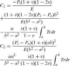
The unknown constants C1 and C2 are given in Appendix.
3.2The case of plane stressFor the case of plane stress the stress-strain relations are
For The case of plane stress the differential equation for displacement ur is
The solution of Eq. 23 is
The corresponding stresses are
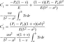
To determine the constants C1′ and C2′ boundary conditions have to be used which are the same as those for the case of plane strain (see Eq. 19). The unknown constants C1′ and C2′ are given in Appendix.
4Creep behavior analysis of the cylinderFor materials with creep behavior, we use Norton’s low to describe the relations between the rates of stress (σ˙ij) and strain (ϵ˙ij) in the multi-axial form
where D and N are material constants for creep. σeff is the effective stress, Sij is the deviator stress tensor. The relations between the rates of strain and displacement are
And the equilibrium equation of the stress rate is
For the case of plane strain (ϵ˙zz=0), the relations between the rates of stress and strain are
For the case of plane stress (σ˙zz=0), the relations between the rates of stress and strain are
where
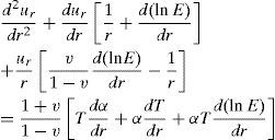
4.1The case of plane strainSubstituting Eqs. 30 and 31 into Eqs. 33 and 34 and then into Eq. 32 gives the differential equation for u˙r in cylinder
where
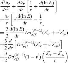
For a homogeneous and isotropic material, Young’s modulus (E) is constant, also the case of v, d and N being constant is studied in this article, therefore, Eq. 39 on simplifying yields
In general, the quantities σeff, Srr' and Sθθ' are very complicated functions of the coordinate r, even in an implicit function form. Therefore, it is almost impossible to find an exact analytical solution of Eq. 41. We can find an asymptotical solution of Eq. 41. At first, we assume that σeff, Srr' and Sθθ' are constant, i.e. they are independent of the coordinate r. Then, the solution of Eq. 41 is
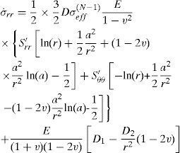
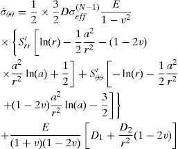
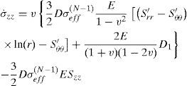
where the unknown constants D1 and D2 can be determined from the boundary conditions. The corresponding stress rates are
To determine the unknown constants D1 and D2 in each material, boundary conditions have to be used. Since inside and outside pressures do not change with time, the boundary conditions for stress rates at the inner and outer surfaces may be written as
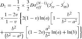
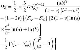
Using these boundary conditions the constants D1 and D2 are obtained
When the stress rate is known, the calculation of stresses at any time ti should be performed iteratively
where
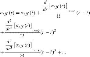
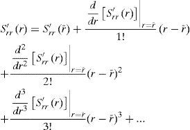
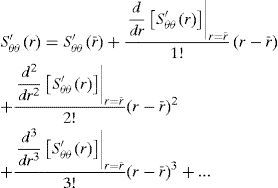
To obtain a generally useful solution, a higher order approximation of σeff, Srr' and Sθθ' should be made
where r¯ is the center point of the wall thickness in the following analysis.
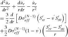
4.2The case of plane stressThe differential equation for u˙r is
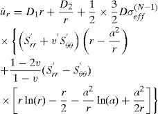
The solution of Eq.54 is
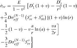
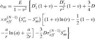
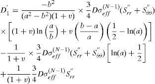
where the unknown constants D1' and D2' can be determined from the boundary conditions. The corresponding stress ratesare
5Numerical results and discussionIn the previous sections, the analytical solution of creep stresses for hemogeneous thick-walled cylindrical vessels subjected to uniform pressures on the inner and outer surfaces were obtained. In this section, some profiles are plotted for the radial displacement, radial stress, circumferential stress and axial stress as a function of radial direction and time.
A cylinder with creep behavior under internal and external pressure is considered. Radii of the cylinder are a = 20 mm, b = 40 mm. The other data are
E = 207 GPa, v = 0.292 α = 10.8x10⁻⁶ K−1, N = 2.25 λ = 43 W/m.°C, Pi=80 MPa, Po=0 MPa, D = 1.4x10⁻⁸, qa=3000 W/m2, h∞=6.5 W/m2.°C, T∞=25 °C
The thermal loading is as follows: inner surface is exposed to a uniform flux, qa, and the outer surface is exposed to an airstream at T∞.
5.1The case of plane strainThe stress distribution after 10h of creeping are plotted in Figure. 2, Figure 3 and Figure 4 for the stress components σrr, σθθ and σzz respectively. It must be noted from Figure. 2, Figure 3 and Figure 4 that, all three stresses are comperesive and the values of all three stresses decreases as radius increases. The absolute maximums of radial, circumferential and axial stresses occur at the inner edge. It means the maximum shear stress which is τmax = σθθ − σrr/2 will be very high on the inner surface of the vessel.
The time dependent stresses at point are plotted in Figure. 5, Figure 6 and Figure 7. Radial, circumferential and axial stresses decreases as time increases.
According to Figure. 5 to Figure 7, all three stresses are comperesive. The radial displacement along the radius for the condition of plane strain is plotted in Figure 8. It must be noted from Figure. 8 that the maximum value of radial displacement is at the inner surface.
5.2The case of plane stressThe stress distribution after 10h of creeping are plotted in Figure. 9 and Figure 10 for the stress components σrr and σθθ respectively. It must be noted from Figure. 9, that for r/a≺1.08 the value of radial stress increases as radius increases while for r/a≻1.08 The value of radial stress decreases as radius increases. According to Figure 10, the value of circumferential stress decreases as radius increases. It can be seen that, radial and circumferential stresses are compressive.
The time dependent stresses at point r = 30 mm, are plotted in Figure. 11 and Figure 12. The radial and circumferential stresses decreases as time increases.
According to Figure. 11 and 12, radial and circumferential stresses are compressive. The radial displacement along the radius for the condition of plane stress is plotted in Figure 13. There is an decrease in the value of the radial displacement as radius increases.
6ConclusionsIn the present study, an analytical solution procedure has been developed for the time-dependent creep analysis of an internally and externally pressurized, thick-walled cylindrical pressure vessel subjected to internal heat flux. For the stress analysis in a cylinder, having material creep behavior, the solutions of the stresses at a time equal to zero (i.e. the initial stress state) are needed, which correspond to the solution of materials with linear elastic behavior. The analytical solution is obtained for the conditions of plane strain and plane stress. Norton’s power law of creep is employed to derive general expressions for stresses and strain rates in the thick cylinder. The pressure, inner radius and outer radius are considered constant. Material properties are considered as constant. The heat conduction equation for the one-dimensional problem in polar coordinates is used to obtain temperature distribution in the cylinder.
According to stress distribution after 10h of creeping for the case of plane stress, both radial and circumferential stresses remains compressive over the entire cylinder radius. It must be noted that for the case of plane stress, the maximum value of circumferential stress at the point mm, is at a time equal to zero (i.e. the initial stress state) and it decreases as time increases. According to stress distribution after 10h of creeping for the case of plane strain, the maximum value of all three stresses are at a time equal to zero, in other word all three stresses decreases as time increases.


