


This paper presents modified neural network for dynamic control and operation of a hybrid generation systems. PV and wind power are the primary power sources of the system to take full advantages of renewable energy, and the diesel-engine is used as a backup system. The simulation model of the hybrid system was developed using MATLAB Simulink. To achieve a fast and stable response for the real power control, the intelligent controller consists of a Radial Basis Function Network (RBFN) and an modified Elman Neural Network (ENN) for maximum power point tracking (MPPT). The pitch angle of wind turbine is controlled by ENN, and the PV system uses RBFN, where the output signal is used to control the DC I DC boost converters to achieve the MPPT. And the results show the hybrid generation system can effectively extract the maximum power from the PV and wind energy sources.
Wind and solar power generation are two of the most promising renewable power generation technologies. Variable-speed wind turbines have many advantages that are well documented in the literature [1], [2]. The wind turbine can operate with maximum aerodynamic efficiency, and the power fluctuations can be absorbed as an inertial energy in the blades. In some applications, the wind turbine may be augmented by an additional power source, usually a diesel generator. These systems are called wind-diesel systems [3], [4] and may be used to supply electricity energy to stand-alone loads, e.g., small villages that are not connected to the main utility. Most diesel generation systems operate at a constant speed due to the restriction of constant frequency at the generator terminals. However, diesel engines have high fuel consumption when operating with light load and constant speed. In order to improve the efficiency and avoid wetstacking, a minimum load of about 30% to 40% is usually recommended by the manufacturers [5]. Variable-speed operation can increase the efficiency, where the fuel consumption can be reduced up to 40% [5], especially when operating with a light load. Moreover, the life expectancy can increase with a lower thermal signature. To avoid the frequent start/stop of the diesel generator, an energy storage system is often used.
Topologies of the power electronic converter for Maximum Power Point Tracking (MPPT) [6] and voltage conversion are studied in this paper. The maximum power point of photovoltaic array is variational, so a search algorithm is needed according to the current-voltage (l-V) and power-voltage (P-V) characteristics of the solar cell. The Perturbation and Observation (P&O) MPPT algorithm is commonly used, due to its ease of implementation. It is based on the observation that if the operating voltage of the PV array is perturbed in a given direction and the power drawn from the photovoltaic (PV) array increases, which means that the operating point is moving toward the MPP, so the operating voltage must be further perturbed in the same direction. Otherwise, with the operating point moving away from the MPP, the direction of the operating voltage perturbation must be reversed. By using P&O method, impedance matching is conducted between boost converter and photovoltaic array in order to realize the MPPT function [7], [8].
The general requirements of MPPT are: simple, low cost, quick tracking when condition changes and small output power fluctuation. The traditional methods are simple and low cost without good tracking performance, such as hill climbing, P&O, and incremental conductance, etc. Novel methods are developed with higher accuracy but complex process, such as optimum gradient method, fuzzy logic control (FLC) and neural networks (NN). These technique could also be costly, difficult to implement, and may not be stable enough [7], [8]. RBFN has a faster convergence property than common multiplayer-perceptron (MLP) neural networks, but with a simpler network structure. RBFN also has a similar feature as the fuzzy-logic system, where the output value is calculated using the weighted-sum method, and the number of nodes in the hidden layer is the same as that of the “if-then” rules of the fuzzy system. The receptive field functions of the RBFN are also similar to the membership functions of the premise part of the fuzzy-logic system. With advantages of multiple facets and the self-adapting capabilities, RBFN is very useful for controlling nonlinear and time-varying dynamic systems where uncertainties and parameter variations need extra attention [9].
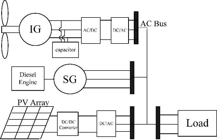
2Analysis of system overviewThe proposed PV and diesel-wind hybrid system is shown in Figure 1. Dynamic models of the main components were developed using MATLAB/Simulink, consisting of
- (1)
wind energy conversion system (WECS)
- (2)
diesel generator system,
- (3)
PV generation system.

In order to capture the maximal wind energy, it is necessary to install the power electronic devices between the WTG and the grid where the frequency is constant. The input of a wind turbine is the wind and the output is the mechanical power turning the generator rotor [6]. For a variable speed wind turbine, the output mechanical power available from a wind turbine could be expressed as
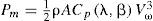
where ρ and A are air density and the area swept by blades, respectively. Vω is the wind velocity (m/sec), and Cp is called the power coefficient, and is given as a nonlinear function of the tip speed ratio (TSR) λ with

where r is wind turbine blade radius, and ωr is the turbine speed. Cp is a function of λ and the blade pitch angle β.
2.2Diesel-Generator Set Model and Excitation SystemThe Diesel generator set (DGS) model is made of combustion, drive train, and synchronous generator models. A common governor model is used in this paper; the essential features can be described by the transfer function described in [3].The excitation system used in diesel generator is Type-1 excitation model taken from IEEE standard 421.5 [10].
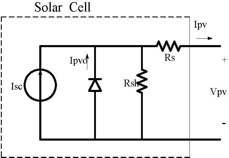
2.3Photovoltaic Array ModelPV cell is a p-n junction, with characteristics similar to diodes. Parameters of the PV cell are shown in Figure 2. The relation between the array terminal current and voltage is [7]
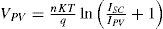


where Rs and Rsh are series and shunt resistances, respectively. ISC is the light induced current, n is the ideality factor of p-n junction, lPVO is the diode saturation current, K is Boltzmann constant (8.63×10⁻⁵ J/ºK), and q is the electronic charge. ISC depends on the irradiance level S and the array temperature T with
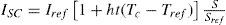
where Iref is the short-circuit current under the reference irradiance strength Sref and temperature Tref, ht is cell module temperature coefficient, while IPVO depend on 7 only [7], [11].
3MPPT Control Algorithm of PV SystemWith the cost of PV cell, it is necessary to implement MPPT to have the voltage operating close to the maximum power point under the changing environment. The proposed PV system is composed of an array of 4×4 panels, a dc/dc converter, a battery storage, dc/ac inverter and a control algorithm, generally performed by a microcontroller to track the maximum power continuously. MPPT is also used to provide a constant voltage to the required load.
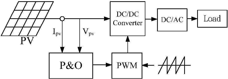
3.1Perturbation and Obsrvation MethodThe most common method in this field is the P&O method [12]. It periodically increases or decreases the PV cell’s voltage as mentioned before to seek the maximum power point. In this paper, a variable step method is proposed to search for the maximum power point, where the step lengths are adjusted according to the distances to the MPP. The ratio of the variation of power (P) to voltage (V) is considered as the step length of duty ratio D, which is actually the slope of each operating point under very short sampling time. Figure 3 shows the control block of the P&O method.
3.2RBFN Controller Design
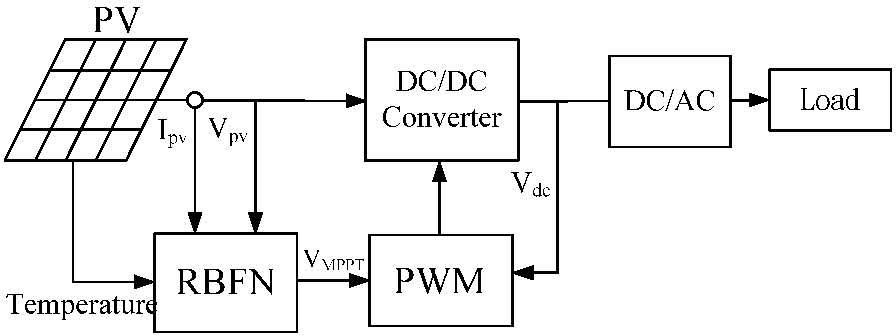
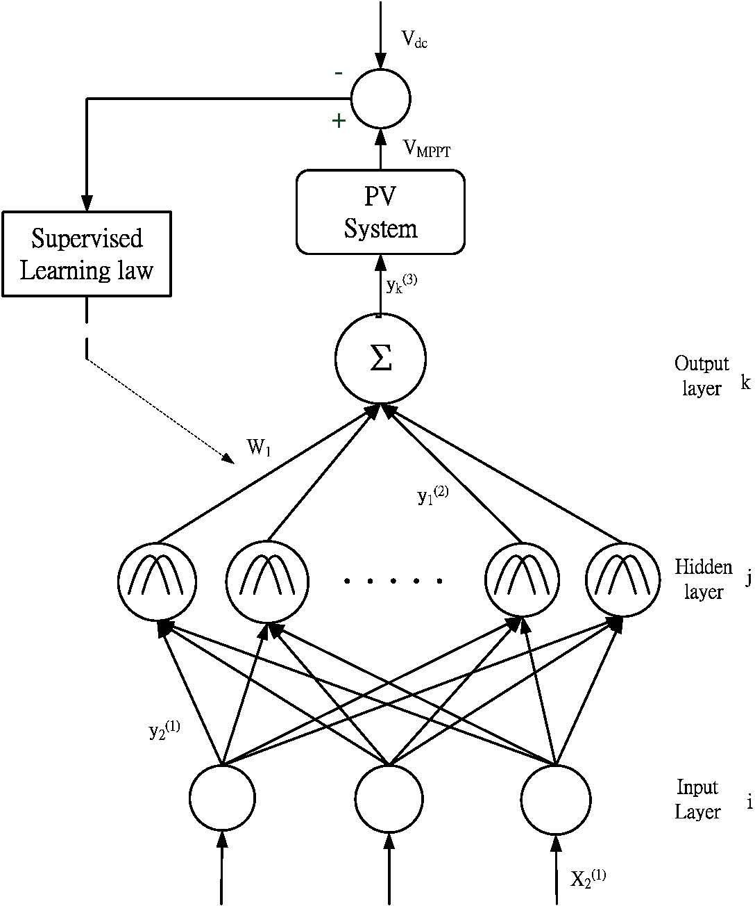
Once the IENN is initialized, a supervised learning is used to t A three-layer RBFN neural network with a boost converter shown in Figure 4 is adopted to implement the controller [13], [14] where the control law VMPPT is generated, and x11=VPV,x21 = IPV and x31= Temperature. In the proposed RBFN, the number of units in the input, hidden, and output layers are three, nine and one, respectively. In order to apply RBFN control, PV system in Figure 5 is linearized in this section. The PWM module is used to generate PWM pulses to control the duty cycle of the switch.


Layer 1.Input Layer
The nodes in this layer are used to directly transmit the numerical inputs to the next layer. The net input and output are represented as

Layer 2. Hidden Layer
Every node performs a Gaussian function. The Gaussian function, a particular example of radial basic functions, is used here as a membership function. Then


where Mj = [m1j m2j … mij]T and ∑j=diag1/σ1j2 1/σ2j2… 1/σij2T denote the mean and the standard deviation (STD) of the Gaussian function.
Layer 3. Output Layer
The single node k in this layer is denoted by Σ, which computes the overall output as the summation of all incoming signals by
where wj are the connective weight between the hidden and the output layers.
Once the RBFN has been initialized, a supervised learning law of gradient descent is used to train this system. The derivation is the same as that of the back-propagation algorithm. It is employed to adjust the parameters mij, σij, and wi of the RBFN by using the training patterns. By recursive application of the chain rule, the error term for each layer is calculated, and updated. The adjustment of the parameters for learning and the weight of links enhances the performance of PV systems. The purpose of supervised learning is to minimize the error function E expressed as
where Vdc and VMPPT represent the reference output voltage and the actual output voltage. A common supervised training algorithm is used in this paper, the essential features can be described in [13], [14].
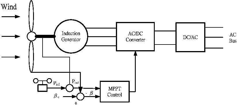
4MPPT Control Algorithm of Wind Energy System4.1Wind Energy Controller DesignThe wind power generation system studied in this paper is shown in Figure 6, composed of an induction generator, a current control PWM ac/dc converter, a field-orientation mechanism, including the coordinate translator, a current controlled dc/ac inverter and the MPPT controller where PI and ENN were studied in this paper. A power controller of the dc/ac inverter in Figure 6 may be constructed in normal operation of the hybrid system. The dc-bus voltage is regulated at a constant value so that real power generation from the wind turbine can pass into the grid. By using the reference frame theory and the linearization technique, the field-oriented induction generator system can be reasonably represented by the control system block diagram shown in Figure 7.
4.2Modified Elman Neural Network (ENN) Controller Design

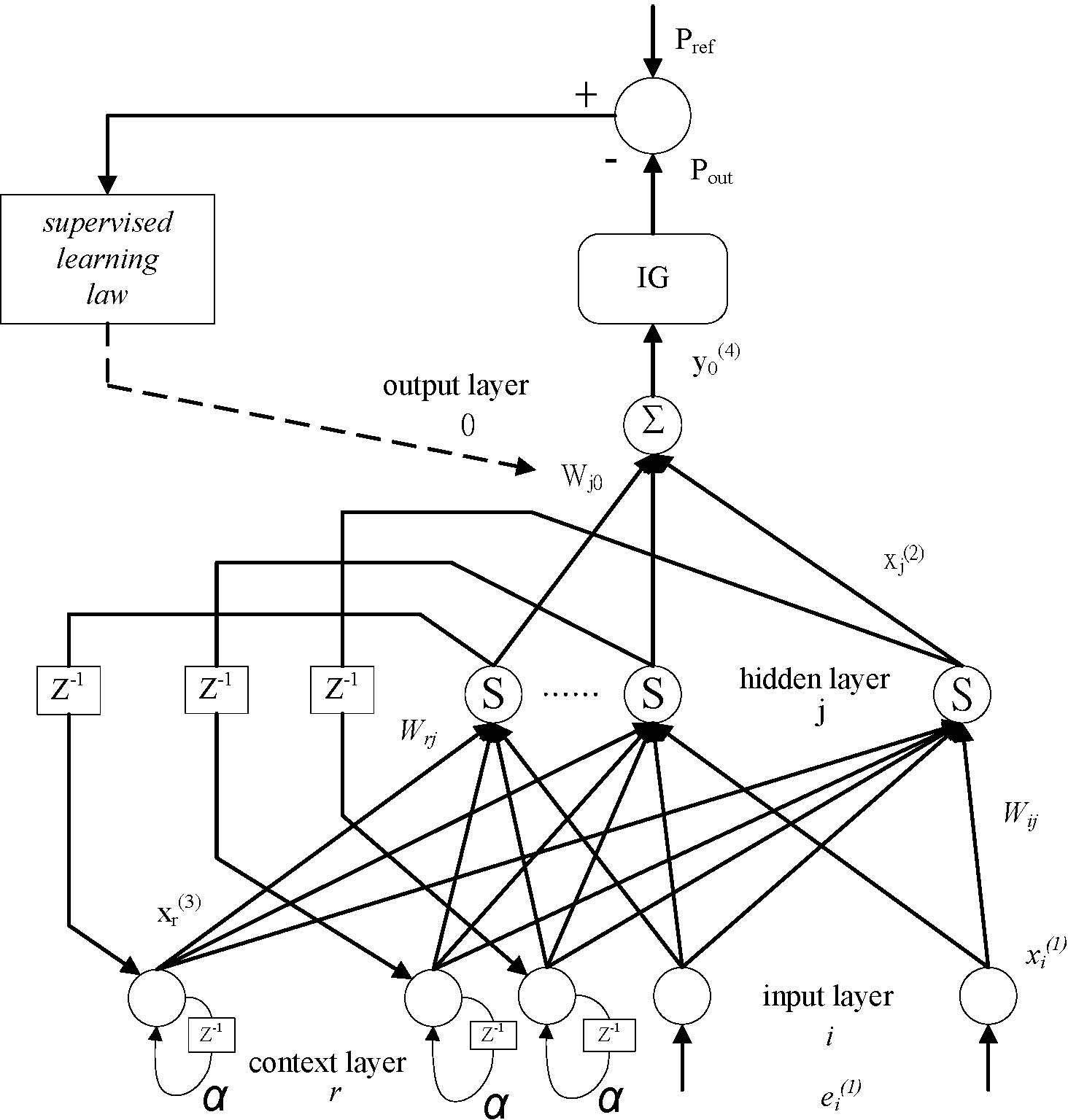
The architecture of the proposed ENN including the input layer, the hidden layer, the context layer and output layer with two inputs and one output is shown in Figure 7, where the control law is defined as iq*, and the ENN input is e1(1) and e2(1) with e1(1) = Pref- Pout and e2(1) = βc−β in this study. The proposed ENN [15-16], takes the feedback into account, and a better learning efficiency can be obtained.
Moreover, to make the neurons sensitive to the history of input data, self-connections of the context nodes and output feedback node are added. So, the proposed ENN combines the ability of dealing with nonlinear problems and can effectively improve the convergence precision and reduce learning time. The signal propagation and the basic function in each layer is introduced below.
Layer 1.Input Layer
In the input layer, the node is defined by
where k represents the kth iteration, ei(1)(k) and xi(i)(k) are the input and the output of the layer.
Layer 2. Hidden Layer
In the hidden layer, the node is defined by


where xi(1), xr(3) and are input and xj(2)(k) is output of the hidden layer. xr(3)(k) is also the output of the context layer, and Wij and Wrj are the connecting weights of input neurons to hidden neurons and context neurons to hidden neurons, respectively.
Layer 3. Context Layer
In the context layer, the node input and output are represented as
where 0 < α < 1 is the self-connecting feedback gain.
Layer 4. Output Layer
In the output layer, the node input and output are represented as
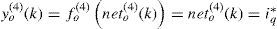
where Wjo is the connecting weight of hidden neurons to output neurons, and yo(4)(k) is the output of the modified ENN and also the control effort of the proposed controller.
Once the ENN has been initialized, a supervised learning is used to train this system based on gradient descent. The derivation is the same as that of the back-propagation algorithm. It is employed to adjust the parameters Wjo, Wrj, and Wij of the ENN by using the training patterns. By recursive application of the chain rule, the error term for each layer is calculated, and updated. The purpose of supervised learning is to minimize the error function E expressed as
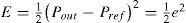
where Pout and Pref represent the actual output power and the reference output power of the generator, respectively, and e denotes the tracking. A common supervised training algorithm is used in this paper, the essential features can be described in [15]-[17].
5Simulatin ResultsThe hybrid system shown in Figure 1 is implemented in the Matlab I Simpower
environment. Many tests were conducted to show performance of the model under various conditions, with the comparison of various MPPT schemes including the typical PI control and P&O method.
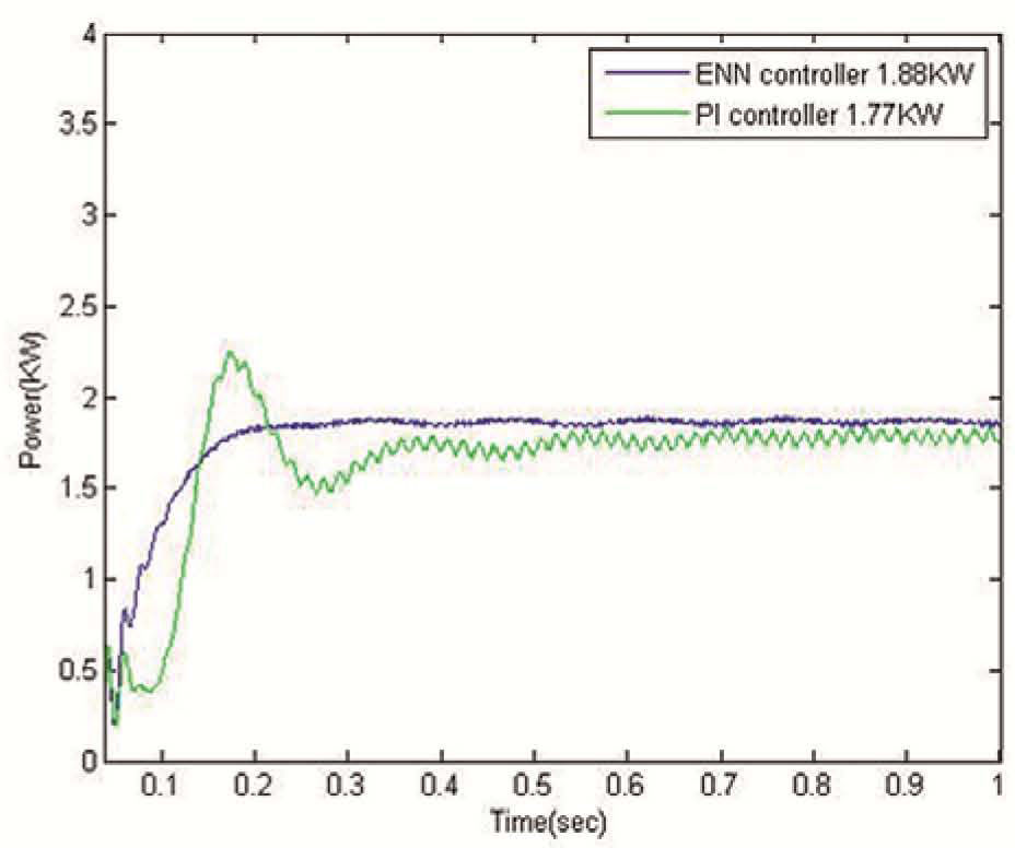
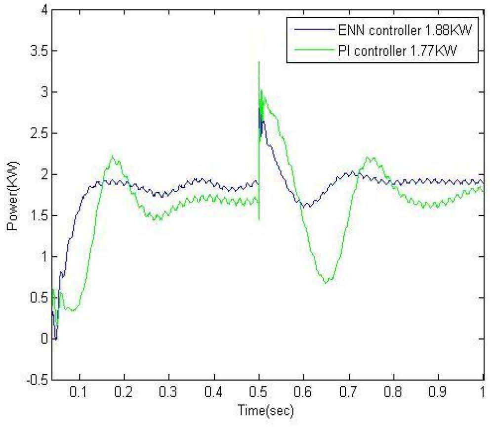
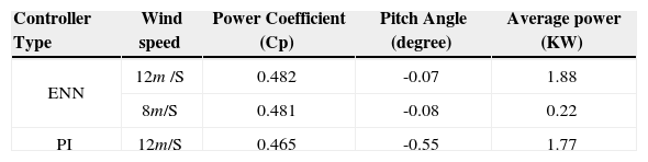
5.1MPPT System PerformanceWind power MPPTTime domain simulation was run for the hybrid power system with constant load under sufficient wind and irradiance. The output power from WECS is shown in Figure 8. From Figure 8, it can be seen that the ENN controller provides a better control performance than PI with less transient and smaller vibrations. The transient response of the design at the start point can be seen clearly that PI fluctuate much more, but ENN oscillates only slightly. The average power is 1.88KW. Compared with that of the PI control, it increases by 6.2%. With different wind speeds, the performance comparison is shown in Table 1.
PV Power MPPT
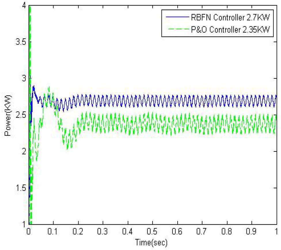
The output power from PV is shown in Figure 9. From Figure 9, we can see that the RBFN controller provides a better performance than P&O, both in the transient and the stability. The average power is 2.7KW. Compared with that of P&O, it increases by 14.89%. The RBFN method can quickly and accurately track the maximum power output for PV array.
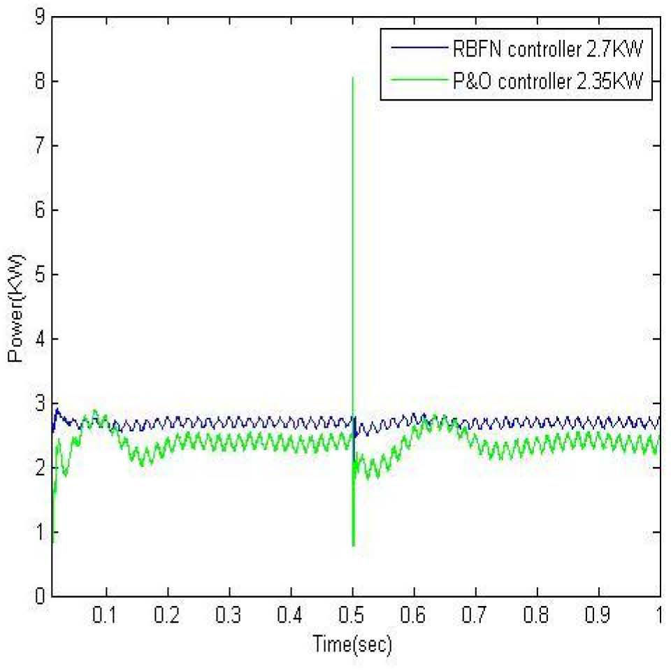
5.2MPPT with Load Change
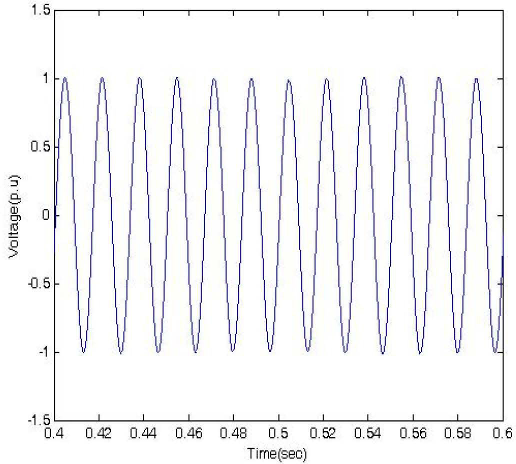
With sufficient wind and irradiance, Figure 10 and 11 show the comparison of the proposed algorithms with PI and P&O methods for a sudden load change from 3KW to 4KW. The DC link voltage slightly decreases and then recovers in around 0.1 sec. The grid frequency response won’t change as can be seen in Figure 12. The proposed method can track faster with a more stable output power under load disturbance.
6Conclusion


In this paper, a PV and diesel-wind hybrid generation system was proposed and implemented. This stand-alone hybrid generation system can effectively extract the maximum power from the wind and PV energy sources. From the case studies, it shows that voltage and power can be well controlled in the hybrid system under a changing environment. An efficient power sharing technique among energy sources are successfully demonstrated with more efficiency, a better transient and more stability, even under disturbance.
The simulation model of the hybrid system was developed using MATLAB/Simulink. The load frequency is regulated by the diesel generator by imposing the rotor currents with the slip frequency. The electrical torque of the WECS generator is controlled to drive the system to the rotational speed where maximum energy can be captured. Depending on the load size and the power supplied by the WECS generator, the control system regulates the DGS rotational speed to minimize the fuel consumption.
The author would like to thank the National Science Council of the Republic of China, Taiwan for financially supporting the research under Contract No. NSC 102-2221-E-269-018.